Page 3
• Use the correct tools for the job. • Keep the tools clean and in good condition. • Always use HYSTER APPROVED parts when making repairs. Replacement parts must meet or exceed the specifications of the original equipment manufacturer. • Make sure all nuts, bolts, snap rings, and other fastening devices are removed before using force to remove parts.
Page 5
Thanks very much for your reading, Want to get more information, Please click here, Then get the complete manual NOTE: If there is no response to click on the link above, please download the PDF document first, and then click on it. Have any questions please write to me: admin@servicemanualperfect.com...
Page 6
Table of Contents Reach Carriages TABLE OF CONTENTS (Continued) Remove ................................Disassemble ..............................Clean and Inspect ............................Assemble ................................ Install ................................Carriage or Reach Assembly Adjustments ....................... Adjust Wear Plug............................Adjust Side Rollers ............................Adjust Thrust Rollers ............................ Adjust Reach Cylinders ..........................Specifications..............................
4500 SRM 971 Safety Procedures When Working Near Mast General This manual has a description and the repair procedures for the single-reach and double-reach carriages on two-stage or three-stage masts. Safety Procedures When Working Near Mast WARNING All chains, ropes, and lifting equipment MUST •...
Page 8
Safety Procedures When Working Near Mast 4500 SRM 971 Legend for Figure 1 A. TWO-STAGE MAST B. THREE-STAGE MAST 1. OUTER WELDMENT 2. INNER WELDMENT 3. INTERMEDIATE WELDMENT 4. SAFETY CHAIN 5. FREE-LIFT CYLINDER 6. CARRIAGE Figure 1. Safety Chain the Mast...
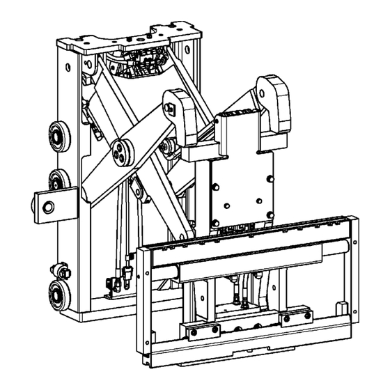
4500 SRM 971 Description Description The reach carriages are used to extend the reach of by a scissor linkage. The top of the scissor arm the carriage. There are two types of reach carriages. weldment at the inner frame is fastened to the top There is a single-reach carriage with one set of scis- of the inner frame by pins.
Page 10
Description 4500 SRM 971 Figure 2. Hydraulic Parts for Double-Reach Assembly (Single-Reach is Similar)
Fork Replacement 4500 SRM 971 Fork Replacement HOOK FORKS WARNING Forks are heavy and can cause an injury. DO NOT try to remove forks without using a lifting device. These forks are connected to the carriage by hooks. Latch pins fit through the top fork hooks and into slots on the top crossmember of the carriage to keep the forks in position.
4500 SRM 971 Reach Assembly Removal and Installation Reach Assembly Removal and Installation 1. Operate the LIFT/LOWER controls to raise the 7. Hold the lift chains to keep them from falling. reach assembly until the rollers of the rear frame Remove the pins in the chain anchors at the back (reach) are above the top of the outer weldment.
Carriage Load Rollers Removal and Installation 4500 SRM 971 Carriage Load Rollers Removal and Installation For the following procedures, refer to Figure 5 and 4. On three-stage masts, remove the safety chains Figure 6. installed in Step 4. Lower the reach assembly for access to the chain anchors at the back of the 1.
4500 SRM 971 Reach Assembly Repair 6. Remove the snap rings from the stub shaft for the 9. Install the reach assembly. See Reach Assembly load roller. Removal and Installation. 7. Use a pry bar to remove the load roller from the 10.
Reach Assembly Outer Frame 4500 SRM 971 Reach Assembly Outer Frame For the following procedures refer to Figure 7, Fig- Move the outer frame away from the lift truck ure 8, and Figure 9. and place it face down on the floor. REMOVE WARNING There are pinch points on the reach car-...
4500 SRM 971 Reach Assembly Outer Frame ASSEMBLE CAUTION 1. To assemble, reverse the removal procedure. Do NOT use steam to clean the load bearings. Do not use compressed air on the bearings. 2. If removed, install the hydraulic hoses for the tilt The bearings are sealed and permanently lu- and sideshift cylinder.
Reach Assembly Outer Frame 4500 SRM 971 The bearings are sealed and permanently lu- CAUTION bricated. The air can force the lubricant out of Do not let the load bearings or shims fall off the the bearings. scissor arms. NOTE: Inspect the load bearings of the scissor arms 5.
Page 21
4500 SRM 971 Reach Assembly Outer Frame 3. Use the crane to move the outer frame for align- CAUTION ment with the scissor arms. Tip the outer frame Do not let the load bearings or shims fall off the forward and align the channels with the load scissor arms.
Single-Reach Scissor Arms 4500 SRM 971 Single-Reach Scissor Arms REMOVE AND DISASSEMBLE 3. Remove the shoulder bolt and nut. Use a drift to remove the pins that fasten the rod ends of the NOTE: The reach assembly must be in the fully-ex- reach cylinders to the scissor arm weldment.
Page 23
4500 SRM 971 Single-Reach Scissor Arms 1. CAPSCREW, LOCKWASHER, 10. MAIN BUSHING 19. SCREW ® AND LOCTITE 11. THRUST WASHER 20. PIN 2. END CAP 12. SHEAVE 21. PIN ROD END 13. RETAINING RING 22. LOCK NUT 3. THRUST WASHER 14.
Single-Reach Scissor Arms 4500 SRM 971 new bushings, all thrust washers, all shims, all stub WARNING shafts, and all pins of the scissor arm assembly. The points between the scissor arms and the rear frame are pinch points and can cause an WARNING injury.
Need help?
Do you have a question about the B453 and is the answer not in the manual?
Questions and answers