Table of Contents
Advertisement
Quick Links
Advertisement
Table of Contents

Subscribe to Our Youtube Channel
Related Manuals for Labconco CApture BT 3170000


Summary of Contents for Labconco CApture BT 3170000
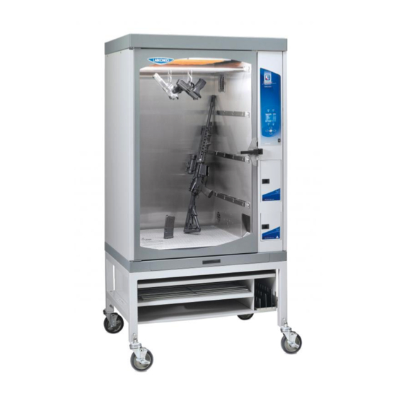
- Page 1 Please read user’s manual before operating equipment Original Instructions LABCONCO CORPORATION 8811 Prospect Avenue Kansas City, MO 64132 (800) 821-5525 I +1 (816) 333-8811 labconco.com User’s Manual CApture BT Fuming Chamber Register this product...
- Page 2 CApture BT Fuming Chamber 2020—Present 3170000 3170001 3170002 3170003 3170004 3170005...
- Page 3 Warranty Labconco Corporation provides a warranty to the original buyer for the repair or replacement of parts and reasonable labor as a result of normal and proper use of the equipment with compatible chemicals. Broken glassware and maintenance items, such as filters, gaskets, light bulbs, finishes and lubrication are not warranted.
-
Page 4: Table Of Contents
Table of Contents 1: INTRODUCTION About This Manual Contents Included 2: BEFORE YOU INSTALL Location Requirements Clearance Requirements Electrical Requirements Exhaust Requirements 3: SAFETY PRECAUTIONS Typographical Conventions General Safety Precautions Safety Precautions for this Product Carbon Filter Life 4: INSTALLATION Unpacking Chamber Installation Chamber Operational Checks... - Page 5 Main Carbon Filter Blowers LED Light Hot Plate Humidifier 6: USING YOUR CAPTURE Feature Overview Initial Chamber Set-Up Initial Chamber Cleaning Keypad & Control Buttons Screen Layout & Information Humidifier Water Fill Chamber Configuration Loading Evidence Alerts CA Fuming – Program Set-up CA Fuming –...
- Page 6 Replace Humidity Sensor (As Needed) Tubing Cleanout (As Needed) Cleaning Cycle Service Operations Manual Override of Main Door Lock Moving the Chamber Storage Service Components – Upper Compartment Service Components – Side Compartment Service Components – Humidifier Assembly (Item 16) Service Parts –...
- Page 7 Chamber Display will not turn on Chamber will not achieve humidity Chamber does not exhaust CA fumes Door alarm active when door(s) closed Hot Plate will not achieve temperature set point White CA residue builds on inside of Chamber Heavy Background CA on evidence APPENDIX A: CONSUMABLES LIST APPENDIX B: DIMENSIONS APPENDIX C: SPECIFICATIONS...
-
Page 8: 1: Introduction
1: Introduction Congratulations on the purchase of a Labconco CApture BT Fuming Chamber. The chamber is designed to protect you and the room environment from Cyanoacrylate vapors produced while fuming evidence with CA glues. The CApture BT Fuming Chamber is the result of years of experience in manufacturing laboratory equipment, and users like you suggested many of its features to us. -
Page 9: 2: Before You Install
2: Before You Install Before you install the product, the site should be prepared for installation. Examine the location where you intend to install it. You must be certain that the area is level and of solid construction. In addition, a dedicated source of electrical power must be located within 10 feet (3 m) of the installation site. -
Page 10: Exhaust Requirements
Exhaust Requirements The CApture BT Fuming Chamber does not require exhaust ducting. The unit filters the chamber air through a pre-filter and a main carbon filter to remove Cyanoacrylate vapors. Clean exhaust air from the chamber is recirculated back into the room. -
Page 11: 3: Safety Precautions
3: Safety Precautions Before unpacking, installing, operating, maintaining, or servicing this equipment, read the following safety warnings and precautions. Avant le déballage, l’installation, le fonctionnement, l’entretien ou la maintenance de cet équipement, lire les avertissements de sécurité et les précautions d’emploi. –... - Page 12 – Air or components that will be very hot. BURN RISK (HIGH TEMPERATURE) Take care not to touch these defined areas. Failure to avoid these areas may result in moderate to severe injury. – Air ambiant ou RISQUE DE BRÛLURE (TEMPÉRATURE ÉLEVÉE) composant devenant très chaud.
-
Page 13: General Safety Precautions
– Do not lift or move this equipment without assistance. LIFTING HAZARD – Ne pas soulever ou déplacer cet équipement sans DANGER DE LEVAGE assistance. – Magnets or magnetic field present. MAGNETIC FIELD IN USE – Présence d'aimants ou de champ CHAMP MAGNETIQUE UTILISE magnétique. - Page 14 Never contact moving parts with your person. Failure to avoid moving parts will result in moderate to serious injury, death, or damage to property. Ne jamais toucher les parties mobiles. Le non-respect de la consigne consistant à éviter les pièces mobiles peut entraîner des blessures graves, la mort ou des dommages matériels.
-
Page 15: Safety Precautions For This Product
Exceeding this limit may damage the perforated floor and its supports. Excessive weight in the chamber may increase the risk of it overturning. If your application requires loading more than 50 lbs., contact Labconco’s Product Service Department at 800-821-5525 or 816-333-8811 for assistance. Do not exceed the maximum weight limit for the Drawer, Accessory Shelves, Hanging Bar as shown in the table below. - Page 16 ALWAYS replace the Main Carbon Filter when prompted to do so by the Display with a new Filter from Labconco. NEVER reset the Carbon Filter Life Gauge without actually replacing the Filter with a new filter from Labconco.
- Page 17 Before removing service panels, disconnect chamber from ALL POWER. Wait at least 1 minute after disconnecting power cord before opening service panels, in order to allow any moving parts to come to a complete stop. Use only Cyanoacrylate (CA) based glues approved for fingerprint fuming. ALWAYS place the liquid CA glue into a disposable tin, and place the tin onto the Heat Plate.
-
Page 18: Carbon Filter Life
Carbon Filter Life It is very important to change the Main Carbon Filter in the CApture BT Fuming Chamber when prompted (see Section 7: Replace Main Carbon Filter) or sooner if Cyanoacrylate (CA) fumes are detected emitting from the chamber’s exhaust. Never unseal the protective bag around a Carbon Filter before it is ready to be installed in the unit. -
Page 19: 4: Installation
4: Installation With the installation site properly prepared, you are ready to unpack and install the equipment. This section covers how to: • Unpack and move the product • Install the product • Connect electrical service Unpacking The following tools are required to unpack the equipment: •... - Page 20 Note: United States Interstate Commerce Commission rules require that claims be filed with the delivery carrier within fifteen (15) days of delivery. Do not return goods without the prior authorization of Labconco. Unauthorized returns will not be accepted. If the product was damaged in transit, you must file a claim directly with the freight carrier.
- Page 21 Figure 4-1 2x4 BOARDS (NOT INCLUDED) LIFT BRACKETS (4) PALLET BOLTS Step 2 – Installation on the Accessory Stand The chamber is secured to the pallet by four (4) bolts (See Fig. 4-1). To remove the chamber, remove the four (4) bolts from underneath the top skid boards that are holding the chamber to the skid (use 1/2”...
-
Page 22: Chamber Installation
• Leg Levelers (4) – not used if installed onto Accessory Stand If you did not receive one or more of the components listed, or if any of the components are damaged, contact Labconco Corporation immediately for further instructions. Step 2 Warning: The Main Carbon Filter is installed, but it remains sealed in a protective plastic. - Page 23 6. Close and secure the Main Filter Bracket with the two screws removed in step 2. 7. Close and secure the Pre-Filter Cover. Remove the warning sign. Figure 4-2 THUMBSCREW ON PRE-FILTER COVER WARNING SIGN POWER SWITCH...
-
Page 24: Chamber Operational Checks
Chamber Operational Checks Prior to use with evidence, you should perform the following steps and operational tests to ensure the chamber is operating properly. Electrical System Check After plugging the power cord into the top, back of the unit, and into an appropriate wall outlet, turn the power switch on (located on front of main control panel –... -
Page 25: 5: Performance Features
5: Performance Features The CApture BT Fuming Chamber operates using the following principles: • Directional airflow. • Pre-filtration of Cyanoacrylate fumes before the Main Carbon Filter. • Filtration and retention of Cyanoacrylate fumes by the Main Carbon Filter, which contains granular activated carbon. The major components in the chamber are: •... -
Page 26: Directional Airflow
Directional Airflow Directional airflow plays a critical role in CApture BT Fuming Chamber performance. During a Humidity or Fuming Cycle, air is recirculated within the sealed chamber. The Recirculation Blower pulls air in from the top of the chamber, and returns it at the bottom of the chamber (shown in Fig. -
Page 27: Main Carbon Pre-Filter
Main Carbon Pre-Filter Located beneath the Main Carbon Filter is a Pre-Filter (see Fig. 5-2). During an Exhaust or Purge Cycle, this Pre-Filter removes CA vapor before it reaches the Main Carbon Filter. Changing this Pre-Filter regularly, depending on usage, is important. Section 6: Maintaining Your CApture BT for instructions. - Page 28 Identifying the components described is important. See Fig. 5-2 below. See Section 6: Maintaining Your CApture BT for detailed instructions on changing the various Filters. Figure 5-2 MAIN CARBON FILTER LED LIGHT RECIRCULATION BLOWER MAIN CARBON (BEHIND INLET SLOTS) PRE-FILTER PLATE HUMIDIFIER (BEHIND OUTLET...
-
Page 29: 6: Using Your Capture Bt
6: Using Your CApture This section details the functional components, features and proper techniques for safely and efficiently using the CApture BT Fuming Chamber. Feature Overview Figure 6-1 illustrates key areas and components of the product. Figure 6-1 DISPLAY POWER MAIN SWITCH DOOR... -
Page 30: Initial Chamber Set-Up
Initial Chamber Set-Up Once the CApture BT Fuming Chamber has been installed in its final location, the following steps must be performed before running the chamber: 1. Remove tape from all doors and bottom drawer, and any remaining packaging material from around the chamber. If not already completed. 2. -
Page 31: Keypad & Control Buttons
Keypad & Control Buttons Once the chamber is ready for operation, familiarize yourself with the Keypad and Control Buttons located around the Display Screen. See Fig. 6-3. Figure 6-3 BACK ONE SCREEN EXHAUSTS CHAMBER ALWAYS PURGES CHAMBER FOR 5 MINUTES START A PROCESS STOP CURRENT PROCESS IF FUMING CYCLE IN PROGRESS,... -
Page 32: Screen Layout & Information
Screen Layout & Information Once the chamber is ready for operation, familiarize yourself with the display screen layout and where key information is located. See Fig. 6-4. Figure 6-4 MENU/FUNCTION TIME DISPLAY SELECTION ICON MENU/FUNCTION OPTIONS ALERT ICONS: CARBON FILTER CA DOOR OPEN CYCLE LIFE MAIN DOOR OPEN... -
Page 33: Chamber Configuration
Mute: When selected, the keypad buttons will not beep when pushed. Diagnostic: Allows internal component function to be tested for troubleshooting (see Section 10: Troubleshooting for more details). Filter Reorder: Filter part numbers and Labconco Service phone number. -
Page 34: Loading Evidence
Loading Evidence Loading evidence into the main chamber is the first step to running a process cycle in the CApture BT Fuming Chamber. Evidence should be evenly distributed with a minimal amount of evidence surface in contact with any surface inside the chamber, for maximum surface coverage with CA fumes. -
Page 35: Alerts
Alerts Before a fuming cycle can begin, any alerts must be resolved. See Fig. 6-6 to identify each possible alert and the action required to remedy each. Figure 6-6 REPLACE MAIN CARBON FILTER & RESET FILTER LIFE CLOSE MAIN DOOR COMPLETELY ADD WATER TO WATER BOTTLE... -
Page 36: Ca Fuming - Program Set-Up
CA Fuming – Program Set-up If fuming evidence with Cyanoacrylate, you are ready to select the Program, and adjust the program parameters as desired. The CApture BT Fuming Chamber can also Humidify older evidence to rehydrate prints without running the fuming cycle. See Humidify –... - Page 37 The Program Parameters (shown in Fig. 6-8) can be adjusted to desired levels within certain minimum and maximum values. Programs 1-3 are factory defaults for running common fuming cycles. The parameters can be modified in the first three programs, and a cycle ran; however, the modifications will not be saved, and will revert back to the factory default parameters.
- Page 38 Programs 1 through 3 offer three factory default options for common CA fuming methods. These first three programs can be modified, and then run; however, the program changes will not be saved. You can modify and save changes to Programs 4 through 20.
- Page 39 Once the Program Parameters are set as desired, press [OK]. The screen will change CA, which displays the Grams of CA to place in the tin, the current Hot Plate Temperature, and the Fume Time selected by the user in the previous menu screen (see Fig.
-
Page 40: Ca Fuming - Maintenance Notifications
CA Fuming – Maintenance Notifications If maintenance is required to the CApture BT Fuming Chamber, you will receive a notification on the ADD CA screen before you begin a Fuming Cycle (see Fig. 6-11). Figure 6-11 NOTIFICATIONS DISPLAYED IN RED This is just a reminder notification, not an error or alert. -
Page 41: Ca Fuming - Program Run
CA Fuming – Program Run Once the CA Fuming Program Parameters have been established, and you are at the ADD CA menu screen, the fuming cycle is ready to begin. Any alerts must be resolved, as described in Loading Evidence earlier in this section. - Page 42 Once the program begins, the first stage of the fuming cycle is HUMIDITY. The screen will display the following information (see Fig. 6-13) during this stage: Figure 6-13 CURRENT RH% IN CHAMBER TIME SINCE HUMIDITY STAGE HUMIDITY ADDED BEGAN UNTIL USER SET POINT ACHIEVED TOTAL TIME SINCE PROGRAM...
- Page 43 During the RH Dwell stage, the air is circulated inside the chamber. Additional humidity will not be added during this stage, so do NOT open the Main Door or the CA Chamber Door. After the RH Dwell stage is complete (or after the Humidity Stage is complete, if no RH Dwell stage was selected), the program will move to the Fuming stage.
- Page 44 To add time to the Fuming stage while still fuming, press [UP] once. The text TIME? will be displayed on the Fuming stage screen, as shown below in Fig. 6-16: Figure 6-16 ADD TIME? DISPLAYED CA FUME TIME WILL BLINK WHEN TIME CAN BE ADDED CA TIME field will blink.
- Page 45 After the Fume stage is complete, the program will move to the Purge stage. The screen will display the following information (see Fig. 6-17) during this stage: Figure 6-17 TIME SINCE PURGE STAGE BEGAN TIME SINCE PURGE STAGE TIME PURGE STAGE BEGAN TOTAL TIME SINCE PROGRAM...
-
Page 46: Humidify - Program Set-Up
Humidify – Program Set-up If re-humidifying prints, you can utilize the Humidify Cycle functionality to raise the chamber’s relative humidity to any user-selectable level, up to 80% maximum, and hold it at that level for a user-selectable time period. On the Main Menu screen, Select by moving the red arrow to Run menu option, and press [OK]. - Page 47 Figure 6-20 Note: Humidity level can only be increased from ambient. The chamber cannot reduce or decrease the relative humidity. During the Humidity stage, you may see water vapor entering the chamber from the lower, right side wall. This is normal. The displayed Humidity value may drop slightly in the first minute until air is circulated thoroughly.
-
Page 48: 7: Maintaining Your Capture Bt
7: Maintaining Your CApture This section details normal maintenance required for optimal operation of the CApture BT Fuming Chamber. Maintenance Safety Precautions Follow the safety precautions below when performing maintenance operations. • Wear safety glasses, and additional eye, face and breathing protection as required by your Health &... -
Page 49: Recommended Maintenance Schedule
Recommended Maintenance Schedule Table 7-1 Maintenance Frequency Activity Weekly Monthly Annually As Required 25-50 50-100 250-500 500-1000 Approximate # of Cycles • • • • Drain Humidifier Tank • • • Check and Replace Pre-Filter Scrape interior walls and glass to •... -
Page 50: Drain Humidifier Tank (Weekly)
Drain Humidifier Tank (Weekly) Replace water in Humidifier Basin and Water Bottle. This is important to do weekly, especially before the chamber will sit unused for several days (typically on a Friday before sitting unused over the weekend). Follow the steps below to empty the Humidifier Basin and Water Bottle. -
Page 51: Inspect / Replace Pre-Filter (Monthly)
Inspect / Replace Pre-Filter (Monthly) Visual inspect the Pre-Filter. Access the Pre-Filter as follows: 1. Locate the thumbscrew on the Pre-Filter Retainer (see Fig. 7-2). Loosen it until the Pre-Filter Retainer hinges open. Note – If the thumbscrew is too tight to hand turn, a Phillips screwdriver may be used to loosen it. -
Page 52: Clean Internal Surfaces (Monthly)
Clean Internal Surfaces (Monthly) When CA residue builds up on the internal surfaces, it may be necessary to remove it. Residue on the main glass door is particularly detrimental to visual observation of developing prints. Follow the procedure below to remove CA residue: To gain better access to the stainless steel walls/floor inside the chamber, it is recommended to remove the perforated floor, hanging bars, accessory items, and shelf brackets (see Fig. -
Page 53: Vacuum/Clean Recirculation Blower Intake (Monthly)
Vacuum/Clean Recirculation Blower Intake (Monthly) This step may not need to be completed monthly, but visual examination of the Recirculation Blower Intake is recommended. If the intake slots are not clogged or overgrown with CA residue, this procedure need not be completed. If the intake slots are clogged with CA residue, follow this procedure: Unplug the main power cord before proceeding to prevent Recirculation Blower from turning on during this procedure. -
Page 54: Replace Main Carbon Filter (Annually)
Replace Main Carbon Filter (Annually) When the Replace Filter Alert activates, or if Cyanoacrylate fumes are detected emitting from the chamber’s exhaust, replace the Main Carbon Filter as described below. See section Section 3: Carbon Filter Life to understand factors that can reduce Carbon Filter Life. - Page 55 Figure 7-6...
-
Page 56: Recalibrate Humidity Sensor (Quarterly)
Recalibrate Humidity Sensor (Quarterly) The RH Sensor in the CApture BT Fuming Chamber is pre-calibrated at the factory to display the relative humidity inside the chamber. The relative humidity percentage displayed on the screen during a Humidify Stage is accurate within +/-5%. At least annually, or if the accuracy of the relative humidity displayed on screen is in doubt, follow the procedure below to verify or re-calibrate the RH Sensor: 1. -
Page 57: Replace Humidity Sensor (As Needed)
Replace Humidity Sensor (As Needed) The RH Sensor in the CApture BT Fuming Chamber is a consumable. Eventually it will not provide accurate data. If the RH Sensor cannot be recalibrated during annual maintenance (see Recalibrate Humidity Sensor (Annually) previously in this section), follow these steps to replace the Humidity Sensor. - Page 58 4. Disconnect the Harness Connector at the end of the Humidity Sensor from the thru-wall connector mate. To disconnect, press down on the small lever tab on the connector and pull the Harness Connector towards you. 5. Rotate the Humidity Sensor Plate counter-clockwise approximately 30 degrees until it pops free from the three retainer fasteners.
- Page 59 11. Reinstall the Humidity Sensor in to the housing in the Water Bottle Compartment. 12. Once the Sensor is in place, the O-Ring should rest against the housing, and the Humidity Sensor Bracket will be loose. Position the three (3) large cutouts on the Bracket over the three (3) studs on the housing.
-
Page 60: Tubing Cleanout (As Needed)
Tubing Cleanout (As Needed) Over time the internal air paths within the tubing behind the Right Side Service Panel may accumulate CA residue/particulate. The CA typically adheres to the internal walls of the tubing that sends air from the Recirculation Blower to the CA Chamber (Hot Plate area). - Page 61 5. On the Main Menu screen, Select SERVICE, and press [OK]. Enter Password: [UP] [DOWN] [LEFT] [RIGHT] [OK]. After entering the Servicer password, select BLOWER SPEED, and press [OK]. 6. You will be prompted for an Admin Password. Enter Password: [UP] [RIGHT] [DOWN] [START] [OK].
-
Page 62: Cleaning Cycle
Cleaning Cycle When cleaning the inside of the chamber, it may be desirable to pull vapors from CA built up on the internal walls of the chamber away from the user. The CApture BT Fuming Chamber has a Cleaning Cycle that can be enabled while the Main Door is open. -
Page 63: Service Operations
Service Operations The operations in this section provide instructions to service the CApture BT Fuming Chamber in the event a component stops working, or a power loss occurs with evidence in the chamber. This section also provides instructions for moving or storing the chamber. -
Page 64: Moving The Chamber
Moving the Chamber Once installed, the CApture BT Fuming Chamber should not be moved or tipped without first preparing the chamber. If the chamber is installed on the accessory stand, it can be rolled without any preparation. Do not roll the chamber on the accessory stand over rough surfaces, door thresholds, or on uneven surfaces of more than 5 degrees of inclination. -
Page 65: Storage
Storage If the chamber is to be left unused for more than one month, it should be prepared for storage. Follow the instructions below. The chamber should not be stored in areas of excess humidity or temperature extremes. 1. Drain the water from the humidifier. Replace empty Water Bottle. 2. -
Page 66: Service Components - Upper Compartment
Service Components – Upper Compartment Serviceable parts are located in the upper compartment of the CApture BT Fuming Chamber. These components should not need to be maintained by the user, but if a failure occurs, these components can be replaced as follows: ALWAYS UNPLUG THE POWER CORD BEFORE SERVICING THIS PRODUCT! Figure 7-14 1. -
Page 67: Service Components - Side Compartment
If uncertain about servicing components behind the right Side Panel, or have service or part number questions, contact Labconco Service Department at 800-821-5525 or 816- 333-8811. For troubleshooting assistance, see Section 10: Troubleshooting. - Page 68 Figure 7-16 See following pages for additional views and detailed descriptions with part numbers.
- Page 69 Figure 7-17 1. Recirculation Blower – P/N 3172000P Disconnect hoses & wires, remove two (2) Blower Screws, pull up & out. 2. Exhaust Blower – P/N 3182700 Disconnect wires, remove four (4) screws underneath Blower Bracket.
- Page 70 3. Hose, 17.0” – P/N 3175905 Loosen hose clamps on either end, slide hose off fittings. 4. Power Supply, 12VDC – P/N 4586800 Remove three (3) screws on top side of Power Supply. Disconnect wires. 5. PCB Display – P/N 3448002 Remove cables from board (note cable orientation!), remove two (2) T20 Torx Screws on side and two (2) Nyloc Nuts on opposite side of PCB Bracket.
- Page 71 15. Exhaust Vent Valve – P/N 3181000 Disconnect wires, remove two (2) screws & nuts. Slide valve off notch in Flapper. Ensure plunger slot on new valve slides into Flapper notch. 16. Humidifier Assembly – P/N 3198000 (115v); 3198001 (230v) Service Parts - Humidifier Assembly section on following pages.
- Page 72 two (2) nuts on Limit Switch Bracket. Lift Limit Switch and Bracket over threaded studs. Remove two (2) screws & nuts holding Limit Switch to Bracket. Before assembling new Limit Switch, note that the old Limit Switch did not have the silver, metal tang (tab), remove the silver, metal tang (tab) off of the new Limit Switch by twisting it with pliers.
-
Page 73: Service Components - Humidifier Assembly (Item 16)
Service Components – Humidifier Assembly (Item 16) Always drain water from the Humidifier before service. Instructions for draining the Humidifier can be found in Moving the Chamber earlier in this section. Serviceable parts are located in the Humidifier Compartment, these components can be replaced as follows: ALWAYS UNPLUG THE POWER CORD BEFORE SERVICING THIS PRODUCT! Figure 7-18... - Page 74 29. Humidifier Element – P/N 3198400 (115v); 3198401 (230v) Disconnect wires, remove Humidifier Lid, and unscrew Element nut. Slide element into Humidifier Basin and remove. Remove O-Ring (P/N 1645001). 30. Temperature Controller – P/N 3188600 Wiggle wire connectors carefully and disconnect. Remove two (2) screws and nuts.
-
Page 75: Service Parts - Ca Chamber Assembly (#17)
Service Parts – CA Chamber Assembly (#17) Serviceable parts are located in the CA (Hot Plate) Compartment, these components can be replaced as follows: ALWAYS UNPLUG THE POWER CORD BEFORE SERVICING THIS PRODUCT! Figure 7-19 HEATER ASSY SCREWS HOLDER SCREWS CAUTION –... - Page 76 Heater Wire from Removable WAGO Wall Nut Connector behind CA Chamber, disconnect Red Angle Terminal from Item 32. Feed wires through grommets in back side wall of CA Chamber (may have to peel away RTV Silicone to push wires through grommets). Reseal wires w/ Silicone. 32.
-
Page 77: Diagnostics
Diagnostics When troubleshooting the CApture BT Fuming Chamber, it can be helpful to test functionality of critical components individually. The Diagnostic mode allows for the testing of individual components. To access the Diagnostic menu, on the Main Menu, select SETTINGS by moving the red arrow to Settings Menu option, and press [OK]. - Page 78 Humidify Valve Humidifier Valve will open (moderate click sound upon actuation), and then close after 30 seconds. Chamber Light Chamber Light dims, and then returns to full brightness after 30 seconds. Time On for each diagnostic test is with Main Door closed. To run each test indefinitely, open the Main Door before starting the test.
-
Page 79: Resetting A Circuit Breaker
Resetting a Circuit Breaker The CApture BT Fuming Chamber has one (115v) or two (230v) circuit breakers on the rear side. Located next to the power cord connection (see Fig. 7-21), the circuit breakers provide protection should the chamber draw an excessive amount of current. Should a circuit breaker trip, press the white barrel back in. -
Page 80: Humidify Timeout
Before changing the default Humidify Timeout (35 min.), make sure no other problems exist within the unit. Contact Labconco Service Department at (800) 821-5525 or +1 (816) 333-8811 for troubleshooting assistance. -
Page 81: Wiring Diagrams
Wiring Diagrams 100-120V... -
Page 82: 208-230V
208-230V... -
Page 83: 9: Accessories
9: Accessories This section details the available field-installable accessories and approved modifications for your CApture BT Fuming Chamber. CApture BT Stand Stand is specially designed for use with the CApture BT Fuming Chamber. Locking casters allow stationary operation, but still provide mobility for moving the chamber. Manually adjustable height. -
Page 84: Kit, Wire Shelf
Kit, Wire Shelf Wire Shelf fits into Fuming Chamber Side Wall brackets, Chamber can hold up to four (4) Wire Shelves. Allows CA fumes to reach bottom of evidence, and allows hanging numerous small items, such as bags. All stainless steel construction. Available in 1, 2 or 4 piece Kits. -
Page 85: Kit, Mini Bag Clips
Kit, Mini Bag Clips Mini Bag Clips are 1.2” x 0.3” alligator-style clips with a hanging loop. Allows easy hanging of small, light-weight items, such as bags from any accessory Wire Shelf. Kit includes ten (10) Small Clips. Catalog Number 3184300. Security Tags Package of 100 each tamper-evident, labeled tags. -
Page 86: 10: Troubleshooting
10: Troubleshooting This section details common troubleshooting for the CApture BT fuming chamber. Chamber Display will not turn on... -
Page 87: Chamber Will Not Achieve Humidity
Chamber will not achieve humidity... -
Page 88: Chamber Does Not Exhaust Ca Fumes
Chamber does not exhaust CA fumes... -
Page 89: Door Alarm Active When Door(S) Closed
Door alarm active when door(s) closed... -
Page 90: Hot Plate Will Not Achieve Temperature Set Point
Hot Plate will not achieve temperature set point... -
Page 91: White Ca Residue Builds On Inside Of Chamber
White CA residue builds on inside of Chamber... -
Page 92: Heavy Background Ca On Evidence
Heavy Background CA on evidence If evidence (particular metallic substrates) are found to process with a heavy white background (see Figure 10-1 as an example of this phenomenon), this is likely due to over humidification. Take these steps: 1. Check the calibration of the Humidity Sensor (see Section Recalibrate Humidity Sensor (Quarterly) in Section 7). -
Page 93: Appendix A: Consumables List
Appendix A: Consumables List Table A-1 indicates the catalog numbers for the following consumable components and kits. Table A-1 Quantity Item Catalog Number Description Required 3186500 Main Carbon Filter 3181400 Main Pre-Filter 3179230 Humidity Sensor Replacement Kit 3185901 Complete Filter Kit Includes: (1) 3186500 Main Carbon Filter (10) 3181400 Main Pre-Filters... -
Page 94: Appendix B: Dimensions
Appendix B: Dimensions Figure B-1 indicates the product dimensions. All dimensions shown in inches. Figure B-1 Ø 6.0 8.27 34.0 7.30 ACCESSORY EXHAUST CONNECTION KIT... - Page 95 The External and Internal Dimensions of the CApture BT Fuming Chamber mounted on the Accessory Stand (P/N 3182900) are shown in Fig. B-2. Figure B-2 *Locking Brake on Casters adds 1.0 inch to this dimensions.
-
Page 96: Appendix C: Specifications
Appendix C: Specifications Power Data Table C-1 Normal Operating Power Catalog Number (Watts) 317000x 400 W 1 Values are for new product with a clean filter (light and blowers on), and may vary +/- 10%... -
Page 97: Environmental Conditions
Environmental Conditions • Indoor use only • Ambient temperature range: 41° to 104°F (5° to 40°C) • Maximum relative humidity: 80% for temperatures up to 88°F (31°C), decreasing linearly to 50% relative humidity at 104°F (40°C) • Main supply voltage fluctuations not to exceed ±10% of the nominal voltage •...
Need help?
Do you have a question about the CApture BT 3170000 and is the answer not in the manual?
Questions and answers