
Related Manuals for Hoshizaki RTW Series


Summary of Contents for Hoshizaki RTW Series
- Page 1 Date 22-08-2016 Rev No DOC NO VDP/SM/22-01- 2016 COMMERCIAL UNDERCOUNTER REFRIGERATOR/FREEZER RTW & FTW...
-
Page 2: Table Of Contents
Table of Contents: CONTENT PAGE NO Safety Instructions Product Indent Use Dimension Layout Exploded View of all parts Technical Specification Procedure to open the CANOPY Procedure to replace the Evaporator fan motor Procedure to replace the Dew Collector Procedure to replace the Defrost Heater Procedure to replace the Defrost Sensor Procedure to replace the Appliance Sensor Procedure to replace the Condenser Fan Motor... -
Page 3: Safety Instructions
Safety instructions: The following instructions contain important safety precautions an should be strictly observed WARNING: There is a possibility of death or serious injury to the service person and a third party or the user due to improper service operations or defects in serviced products. - Page 4 4) When unbrazing the refrigeration circuit connections, check that the circuit is completely evacuated. The refrigerant may produce a poisonous gas when coming in contact with an open flame. 5) Do not braze in an enclosed room to prevent carbon monoxide poisoning . 6) In case of a refrigerant leak, locate and repair the leaking part completely before recharging the refrigerant and checking for further leaks.
-
Page 5: Product Indent Use
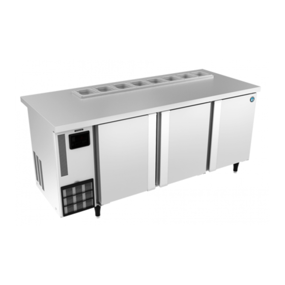
Product Intended Use: RTW Series These products are solid door commercial refrigerator used to store/preserve Refrigerated food products. This is mainly used in commercial establishment. -
Page 6: Dimension Layout
T – Undercounter W– Made by Western Refrigeration DIMENSIONAL LAYOUT: PRODUCT OUTSIDE DIMENSIONS IN MM (WITH LEGS): RTW-120/ FTW-120 1200 (W) x 750 (D) x 850 (H) RTW-150/ FTW-150 1500 (W) x 750 (D) x 850 (H) RTW-180/ FTW-180 1800 (W) x 750 (D) x 850 (H) RTW-126/ FTW-126 1200 (W) x 600 (D) x 850 (H) RTW-156/ FTW-156... - Page 7 INSTALLATION REQUIREMENTS: LOCATION: For best operating results, 1) The under counter should not be located next to ovens, grills and other high heat producing equipment’s. 2) The location should provide a firm foundation for the equipment’s. 3) Do not expose the unit to direct sun light or higher temperatures. 4) Allow 50 mm clearance at front and back of the unit for smooth operation.
- Page 8 3) Turn the unit 90 degrees on the pallet, tilt the unit sideways, and screw in the two adjustable legs. 4) Tilt the unit in opposite direction and screw the other two legs. 5) Slide out the pallet form the unit. 6) Level the freezer in both left and right, front and rear sides.
-
Page 9: Technical Specification
TECHNICAL SPECIFICATIONS RTW-120 RTW-126 Model Power supply Single phase, 230V AC, 50Hz Single phase, 230V AC, 50Hz Amperage 1.5 Amp 1.5 Amp Electrical consumption 290 Watt 290 Watt Heat rejection 0.56 kW 0.56 kW Power cord 10 Amps / 3 meter 10 Amps / 3 meter Effective capacity 295 Liters... - Page 10 TECHNICAL SPECIFICATIONS Model RTW-156MS4 RTW-150MS4 Power supply Single phase, 230V AC, 50Hz Single phase, 230V AC, 50Hz Amperage 1.5 Amp 1.5 Amp Electrical consumption 290 Watt 290 Watt Heat rejection 0.56 kW 0.56 kW Power cord 10 Amps / 3 meter 10 Amps / 3 meter Effective capacity 305 Liters...
- Page 11 TECHNICAL SPECIFICATIONS Model RTW-180MS4 RTW-186MS4 Power supply Single phase, 230V AC, 50Hz Single phase, 230V AC, 50Hz Amperage 1.7 Amp 1.7 Amp Electrical consumption 370 Watt 370 Watt Heat rejection 0.73 kW 0.73 kW Power cord 10 Amps / 3 meter 10 Amps / 3 meter Effective capacity 511 Liters...
- Page 12 TECHNICAL SPECIFICATIONS Model FTW-127MS4-GN FTW-177MS4-GN Power supply Single phase, 230V AC, 50Hz Single phase, 230V AC, 50Hz Amperage 3.9 Amp 3.7 Amp Electrical consumption 600 Watt 600 Watt Defrost Heater: 165W x 2 nos. Defrost Heater: 165W x 2 nos. Heat rejection 1.113 kW 1.32 kW...
- Page 13 ROCEDURE TO REPLACE APPLICATION SENSOR STEP 1 Unscrew the six screws M5 TAPTITE fitted to the panel & remove Fan socket as shown in figure STEP 2 After unscrewing the six screws open the Panel & unscrew the Sensor screw as shown in figure STEP 3 Remove side panel &...
-
Page 14: Procedure To Replace The Defrost Sensor
STEP 4 Remove Application Sensor socket (white colour) from Control panel For fix the Application sensor make reverse steps as shown in figure. PROCEDURE REPLACE DEFROST SENSOR STEP 1 Unscrew the six screws M5 TAPTITE fitted to the panel & remove Fan socket as shown in figure... - Page 15 STEP 2 Remove the Defrost sensor as shown in figure STEP 3 Remove side panel & Pull the Sensor from Evaporator .pipe as shown in figure STEP 4 Remove Defrost Sensor socket (Blue colour) from Control panel For fix the Defrost sensor make reverse steps as shown in figure.
- Page 16 HOW TO ENTER INTO THE CONTROLLER PERAMETERS: 1) Open front panel 2) Press the set key for 3 seconds. The screen displays the PS menu. Press the set button again, the screen displays zero, use up and down key to input the password 22.
- Page 17 STEP 5 STEP 4 After the removal of top cover Now remove the side brackets connected CAREL CONTROLER is visible as on either sides as shown in figure. shown in figure. Now the CAREL CONTROLER can be RELAY BASE OMRON PYF08A-E 2 removed from the power box POLE SOCKET Replace it with new one and adopt the...
-
Page 18: Carel Controller Connections
CAREL CONTROLER CONNECTIONS 1. EVAPORATOR MOTOR 6. INPUT(PHASE) 2. NO CONNECTION 7. INPUT (NUTRAL) 8, 9,10. DEFROST AND APPLIANCE SENSOR DRAIN AND BODY HEATER COMPRESSOR... - Page 19 POWER BOX ASSY HFW-77:...
-
Page 20: Procedure To Replace The Door Gasket
PROCEDURE TO REPLACE DOOR GASKET: Remove the old gasket by pulling it from any of the four corner After that fix the gasket into the groove from any one of the four corners and then simply press looking that the gasket if fixed into the groove throughout the door... -
Page 21: Procedure To Replace The Door Assembly
PROCEDURE TO REPLACE DOOR ASSEMBLY: STEP 1 STEP 2 Step 1: Remove the top door hinge by unscrewing the two screws fixed to the cabinet Step 2:Remove the top door by pulling it upwards as shown in figure Remove the bottom hinge by unscrewing the two screws fixed to the cabinet now you can remove the bottom door by pulling it upwards. - Page 22 CAREL CONTROLER PROGRAM: CAREL PJEZS0G000 ELECTRONIC TEMPERATURE CONTROLLER PARAMETER SETTINGS FOR RTW MODELS Display Parameters Min. Max. Factory setting controller PASSWORD Control temperature ºC/ºF PROBE PARAMETER Mesurment stability Select Probe / input displayed (*) Select °C / °F (0=°C, 1=°F) Disable decimal point Preobe calibration -12.7...
-
Page 23: Carel Controller Alarms
CAREL CONTROLER ALARMS E0- probe 1 error: This error belongs to appliance sensor control, if this error showing on carel display, need to change the appliance sensor fitted in the dew collector assembly. E1- probe 2 error: This error belongs to defrost sensor failure, if this error displays on the carel controller display, need to change defrost sensor fitted in evaporator fins. - Page 24 PROCEDURE TO REPLACE CONDENSER FAN MOTOR STEP 1 Open the Side Panel M4 screw 2NOS & Front Panel M4 screw 2nos as shown in figure STEP 2 Open the condenser fan motor screw 3 nos as shown in figure step 2 STEP 3 Open the Condenser screw 2 nos &...
- Page 25 STEP 4 Open the Condenser Motor bracket screw 2 nos as shown in figure & pull the motor outside then open the fan blade screw & replace motor. REPLACEMENT OF DEFROST HEATER (FTW ONLY) STEP 1 Open the suction duct panel 6 screw as shown in the picture SUCTION DUCT...
- Page 26 Turn & remove the glass tube heater & replace heater. REPLACEMENT OF LED DRIVER (LS4 MODEL) STEP 1 REMOVE THE LED DRIVER TO THE UNIT WITH SCREW S3X12(2Qty) STEP 2 FIX THE LED DRIVER TO THE UNIT WITH SCREW S3X12(2Qty)
-
Page 27: Wiring Drawings
Wiring Drawing:... -
Page 29: Trouble Shooting
Trouble Shooting:... - Page 31 DISPOSAL:...
Need help?
Do you have a question about the RTW Series and is the answer not in the manual?
Questions and answers