
Related Manuals for Hoshizaki RTC-120MNA


Summary of Contents for Hoshizaki RTC-120MNA
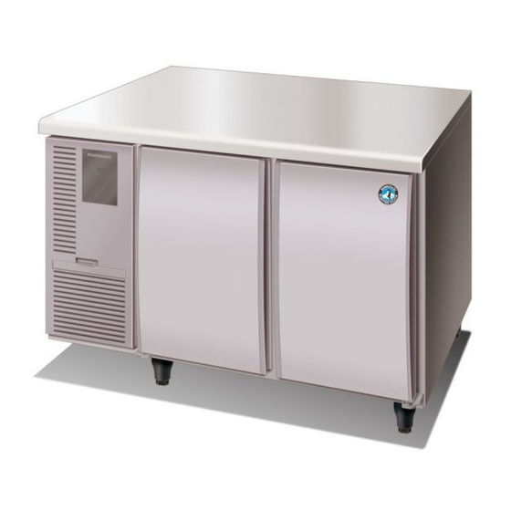
- Page 1 T069-838 ISSUED: MAY 31, 2011 REVISED: JUN. 16, 2014 HOSHIZAKI UNDERCOUNTER REFRIGERATOR/FREEZER RTC-M_A series MODEL FTC- M_A series SERVICE MANUAL...
-
Page 2: Table Of Contents
CONTENTS PAGE I. GENERAL INFORMATION --------------------------------------------------------------------------1 1. SAFETY INSTRUCTIONS -------------------------------------------------------------------------1 2. DIMENSIONS/SPECIFICATIONS ---------------------------------------------------------------3 [a] RTC-120MNA -------------------------------------------------------------------------------------3 [b] RTC-120MDA -------------------------------------------------------------------------------------4 [c] RTC-150MNA -------------------------------------------------------------------------------------5 [d] RTC-150MDA -------------------------------------------------------------------------------------6 [e] RTC-180MNA -------------------------------------------------------------------------------------7 [f] RTC-180MDA --------------------------------------------------------------------------------------8 [g] FTC-120MNA -------------------------------------------------------------------------------------9 [h] FTC-120MDA ----------------------------------------------------------------------------------- 10 [i] FTC-150MNA ------------------------------------------------------------------------------------ 11... - Page 3 3. COMPONENTS ------------------------------------------------------------------------------------ 38 4. CONTROLLER ------------------------------------------------------------------------------------- 40 [a] SERVICING CONTROLLER ---------------------------------------------------------------- 40 [b] CHECKING THERMISTOR ----------------------------------------------------------------- 41 IV. REMOVAL AND REPLACEMENT OF COMPONENTS ---------------------------------- 42 1. REFRIGERATION CIRCUIT -------------------------------------------------------------------- 42 [a] REFRIGERANT -------------------------------------------------------------------------------- 42 [b] COMPRESSOR -------------------------------------------------------------------------------- 42 [c] CONDENSER ---------------------------------------------------------------------------------- 44 [d] DRIER -------------------------------------------------------------------------------------------- 44 [e] EVAPORATOR --------------------------------------------------------------------------------- 44 2.
-
Page 4: General Information
I. GENERAL INFORMATION 1. SAFETY INSTRUCTIONS The following instructions contain important safety precautions and should be strictly observed. The terms used here are defined as follows: WARNING: There is a possibility of death or serious injury to the service person and a third party or the user due to improper service operations or defects in serviced products. - Page 5 be located, be sure to check again for further leaks after recharging the refrigerant. Leaked refrigerant may produce a poisonous gas when coming in contact with an open flame of a gas cooking stove or a fan heater. (7) Before servicing, check the surface temperature of the refrigeration circuit to prevent a burn.
-
Page 6: Dimensions/Specifications
2. DIMENSIONS/SPECIFICATIONS [a] RTC-120MNA... -
Page 7: [B] Rtc-120Mda
[b] RTC-120MDA... -
Page 8: [C] Rtc-150Mna
[c] RTC-150MNA... -
Page 9: [D] Rtc-150Mda
[d] RTC-150MDA... -
Page 10: [E] Rtc-180Mna
[e] RTC-180MNA... -
Page 11: [F] Rtc-180Mda
[f] RTC-180MDA... -
Page 12: [G] Ftc-120Mna
[g] FTC-120MNA... -
Page 13: [H] Ftc-120Mda
[h] FTC-120MDA... -
Page 14: [I] Ftc-150Mna
[i] FTC-150MNA... -
Page 15: [J] Ftc-150Mda
[j] FTC-150MDA... -
Page 16: [K] Ftc-180Mna
[k] FTC-180MNA... -
Page 17: [L] Ftc-180Mda
[l] FTC-180MDA... -
Page 18: Technical Information
II. TECHNICAL INFORMATION 1. WIRING DIAGRAM [a] RTC SERIES... -
Page 19: [B] Ftc-120Mna, Ftc-120Mda, Ftc-150Mna
[b] FTC-120MNA, FTC-120MDA, FTC-150MNA... -
Page 20: [C] Ftc-150Mda, Ftc-180Mna, Ftc-180Mda
[c] FTC-150MDA, FTC-180MNA, FTC-180MDA... -
Page 21: Refrigeration Circuit
2. REFRIGERATION CIRCUIT [a] RTC SERIES Refrigerant: HFC-134a... -
Page 22: [B] Ftc Series
[b] FTC SERIES Refrigerant: HFC-404A... -
Page 23: Electronic Controls
3. ELECTRONIC CONTROLS [a] SET POINT TEMPERATURE (compressor OFF temperature) Off-cycle defrost (RTC series): -2 to +12°C Heater defrost (FTC series): -23 to -7°C Average Cabinet Temperature Time Set Point Temperature Compressor [b] CABINET TEMPERATURE DIFFERENTIAL 4 K (from “set point temp” to “set point temp + 4 K”) The compressor stops when the cabinet temperature reaches down to the set point temperature, and starts when the cabinet temperature rises to the set point temperature + 4°C. -
Page 24: [F] Compressor Soft Start
[f] COMPRESSOR SOFT START 1) Startup Power ON 3 min Compressor Condenser Fan Motor Cabinet Temp Display Interior Fan Motor (RTC) 1 min Interior Fan Motor (FTC) When the power supply is turned on, the screen shows the cabinet temperature and the interior fan motor starts up immediately (RTC series only) or with a 1 minute delay (FTC series). -
Page 25: [H] Checking Set Point Temperature
[h] CHECKING SET POINT TEMPERATURE Note: See “5. CONTROLLER” for the operation panel key locations. RTC series Press and hold the up key on the operation panel to display the set point temperature on the screen. When releasing the up key, the screen displays the cabinet temperature again. FTC series Press and hold the set key on the operation panel for 3 seconds to display “SEt”... -
Page 26: Timing Chart
4. TIMING CHART [a] STARTUP - CONTROL RTC, FTC series 3 min Min 3 min Power Supply Temp Display Frame Heater Compressor Condenser Fan Motor RTC series Interior Fan Motor Interior Thermistor Temp Set Point Temp + 4 K Set Point Temp FTC series 1 min Interior... -
Page 27: [B] Defrost
[b] DEFROST RTC series (Off-cycle defrost) Frame Heater Compressor Condenser Fan Motor Interior Fan Motor Detects end of cycle (5°C) Defrost (Interior) Thermistor Temp Defrost (Until Thermistor detects) Temp Display Temp FTC series (Heater defrost) Frame Heater Compressor Condenser Fan Motor Interior Fan Motor Defrost Heater... -
Page 28: Controller
5. CONTROLLER [a] RTC SERIES [1] Defrost Indicator Light [2] Refrigeration Indicator Light [3] Set Key [4] Defrost/Reset Key [5] Set Indicator Light [6] Screen [7] Down Key [8] Up Key Operation Panel Indicator Lights Indicator Light Symbol Status Meaning Parameter setting Set indicator light Measuring and controlling status... - Page 29 Operations 1. Under temperature measuring and controlling status: 1) Press the set key for 3 seconds: When the keypad password is set as “0”, the set indicator light comes on and the screen displays the “F01” menu. There is no password authentication, so directly enter the menu mode to set parameter.
- Page 30 alarm code E1, with the buzzer doing nothing; close the compressor, when the troubleshooting is over, system will recalculate the compressor delay time. When the door-trip alarms, the controller will flashing indicate the alarm code Defrosting stops automatically when the evaporator temperature reaches the defrost E2, with the buzzer ringing after running the time of "F5".
-
Page 31: [B] Ftc Series
[b] FTC SERIES [1] Fan Indicator Light [2] Set Indicator Light [3] Refrigeration Indicator Light [4] Defrost Indicator Light [5] Defrost Key [6] Down Key [7] Up Key [8] Set Key Operation Panel Indicator Lights Indicator Light Symbol Status Meaning Compressor running Compressor stopped Refrigeration... - Page 32 Parameters Menu Item Range Default Remark User Min temp setting to max temp setting Temp parameter setting 1 to 25°C Return difference setting 0 to 255 min Defrost time 0 to 120 hrs Defrost cycle -45.5°C to SEt Min temp setting SEt to 99.9°C Max temp setting -10 to +10°C...
- Page 33 Operations 1. Compressor functions: A. Under electric heating defrost mode: Start condition: Compressor relay closes when both a) and b) or both a) and c) are met. a) Compressor delay time exceeds the set delay time. b) Forced refrigeration starts when the room temperature is higher than the set point temperature.
- Page 34 3. Fan functions: Fan relay closes when any of the following conditions is met. a) Defrost temperature is higher than the fan stop temperature; Difference between room temperature and evaporator temperature is more than the set difference. b) Operation mode “0”; Compressor starts; Defrost thermistor temperature is lower than the fan stop temperature;...
- Page 35 Wiring Diagram Safety Rules Dangerous ★ : 1、Strictly distinguish the sensor down-lead, power wire and output interface of the relay, and prohibit wrong connections or overloading the relay. 2、It must cut off the power supply before any connecting of the wire terminals. Warning ★...
-
Page 36: Service Diagnosis
III. SERVICE DIAGNOSIS 1. ERROR CODES [a] RTC SERIES Code Display Error Description Possible Cause Reset E1 E1 only Interior Interior thermistor • Interior thermistor • Press any key to thermistor is defective. circuit open, stop beep defective Compressor stops. connector •... -
Page 37: Flowchart
2. FLOWCHART [a] RTC SERIES PROBLEM PROBLEM POSSIBLE CAUSE (numbers corresponding to "3. COMPONENTS") No refrigeration Compressor will not start No temp indication [1] Fuse Blown out [2] Controller Open circuit, connector unplugged E1 error indication [4] Interior Thermistor Abnormal resistance, bad contact No error indication [4] Interior Thermistor Abnormal resistance, bad contact... - Page 38 PROBLEM PROBLEM POSSIBLE CAUSE (numbers corresponding to "3. COMPONENTS") Condensation Frame heater is not energized Open circuit Frame heater is energized Duty ratio too high *Forced drain water evaporation models only: Water leak from Drain water is not evaporated Evaporation pan heater [17] Evaporation Pan Heater Open circuit bottom...
-
Page 39: [B] Ftc Series
[b] FTC SERIES PROBLEM PROBLEM POSSIBLE CAUSE (numbers corresponding to "3. COMPONENTS") No refrigeration Compressor will not start No temp indication [1] Fuse Blown Out [2] Controller Open circuit, connector unplugged No error indication [4] Interior Thermistor Abnormal resistance, bad contact [6] Pressure Switch Defective [3] Relay... - Page 40 PROBLEM PROBLEM POSSIBLE CAUSE (numbers corresponding to "3. COMPONENTS") Excessive Compressor runs continuously High temp indication [4] Interior Thermistor Location refrigeration Normal temp indication [4] Interior Thermistor Abnormal resistance [2] Controller Defective Compressor stops No error indication Cold air outlet loaded Cold air inlet blocked Ambient temp too low LLL, HHH error indication...
-
Page 41: Components
3. COMPONENTS CHART COMPONENT CHECK REMEDY Fuse Blown out Replace Controller Open circuit Correct or replace Input/output (interior fan motor) Replace See wiring label Connector disconnected Correct Connector dusty/dirty Remove 7 segment display partially/totally off Replace Electronic parts defective/burnt out Relay Fast-on terminal/pin disconnected Correct... - Page 42 CHART COMPONENT CHECK REMEDY [10] Defrost Heater Open circuit Correct Conductivity Insulation resistance 1MΩ or more at 500V Replace [11] Thermal Fuse Conductivity Replace Contact welding of relay Replace relay [12] Supply Voltage Check for ±6% of rated voltage Increase power supply capacity Plug into a separate power receptacle [13] Refrigeration Circuit...
-
Page 43: Controller
4. CONTROLLER [a] SERVICING CONTROLLER 1) When receiving a service call, ask the user to turn off the power supply and turn it back on after 30 seconds, while watching the unit. This will reset the controller, and in some cases normal operation will resume. -
Page 44: [B] Checking Thermistor
[b] CHECKING THERMISTOR 1) Remove the thermistor from the controller. 2) Put ice and water in a glass or other container to make 0°C water. Immerse the thermistor bulb in the water for 5 minutes (at the center of the container). 3) Use the Ω... -
Page 45: Removal And Replacement Of Components
IV. REMOVAL AND REPLACEMENT OF COMPONENTS WARNING Always unplug the unit or turn off the main power supply before replacing components. 1. REFRIGERATION CIRCUIT [a] REFRIGERANT Refrigerant R134a used for this unit is not flammable or poisonous itself. It also provides remarkably lower pressure than ammonia or similar substances at the same condensing temperatures. - Page 46 4) Remove the hexagon head bolts with washers securing the condenser fan motor bracket to the base, and remove the condenser fan motor assembly. 5) Remove the screw securing the unit side panel, and take off the side panel. 6) Remove the terminal cover enclosing the compressor electrical parts. 7) Remove the overload relay and start relay.
-
Page 47: [C] Condenser
[c] CONDENSER 1) Pull out the condenser according to steps 1) through 3) of “[b] COMPRESSOR”. 2) Remove the screws securing the shroud to the condenser, and disconnect the shroud. 3) Disconnect the condenser from the refrigeration circuit using brazing equipment. Use a wet towel to protect any flammable materials from burner flame. -
Page 48: Electrical Parts
8) Remove the evaporator cover (and the heater cover with the heater bracket). 9) Remove the defrost thermistor from the evaporator. 10) To replace the removed parts, reverse the above removal procedure. Interior Fan Motor Assembly Evaporator & Heat Exchanger Joint Defrost Thermistor Exhaust Duct Evaporator... -
Page 49: [B] Interior Fan Motor
Heat Exchanger Shroud (Condenser Cover) Compressor Condenser Fan Motor Condenser [b] INTERIOR FAN MOTOR 1) Remove the front panel. 2) Disconnect the interior fan motor leads. 3) Remove the intake and exhaust ducts from inside the cabinet. 4) Remove the insulations in the wire through-hole from inside and outside the cabinet. 5) Remove the interior fan motor assembly. -
Page 50: [C] Defrost Heater, Thermal Fuse
Note: 1. After servicing, insert new insulations into the wire through-hole from inside and outside the cabinet. Do not reuse the removed insulations. 2. Be sure to install the interior fan motor in the proper direction as shown above. [c] DEFROST HEATER, THERMAL FUSE 1) Remove the front panel. -
Page 51: [D] Interior Thermistor, Defrost Thermistor
2. If using two defrost heaters, mark the end of the heater leads to prevent miswiring. 3. If using only one defrost heater, install the heater in the hole on the cabinet side of the heater cover. [d] INTERIOR THERMISTOR, DEFROST THERMISTOR 1) Remove the front panel. -
Page 52: [E] Controller
[e] CONTROLLER 1) Remove the front panel. 2) Unscrew the top and bottom of the control box to remove the control box. 3) Push the stoppers at both sides of the controller, and slide the stoppers to remove the controller. 4) Use a precision flat head screwdriver to loosen the screws and disconnect the wiring from the controller. -
Page 53: Door Gasket
3. DOOR GASKET [a] REMOVAL 1) Open the door. 2) Detach the door gasket from the door liner. [b] REPLACEMENT 1) Spray water on the door liner channel with a sprayer. 2) Fit the four corners of the door gasket into those of the door liner channel. 3) Push in each part of the door gasket from both sides.
Need help?
Do you have a question about the RTC-120MNA and is the answer not in the manual?
Questions and answers