Table of Contents
Advertisement
Quick Links
Installation Instructions
Trane Rental Services
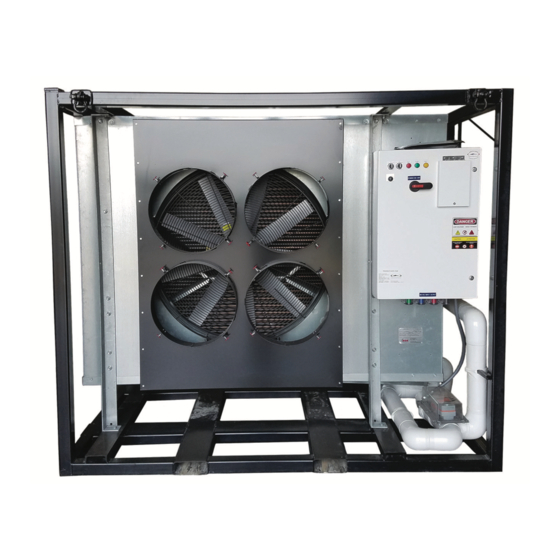
Low-temp Air-handling Unit
Only qualified personnel should install and service the equipment. The installation, starting up, and servicing of
heating, ventilating, and air-conditioning equipment can be hazardous and requires specific knowledge and training.
Improperly installed, adjusted or altered equipment by an unqualified person could result in death or serious injury.
When working on the equipment, observe all precautions in the literature and on the tags, stickers, and labels that are
attached to the equipment.
July 2020
SAFETY WARNING
CHS-SVN011C-EN
Advertisement
Table of Contents

Related Manuals for Trane PCC-1L-3210-4-7.5


Summary of Contents for Trane PCC-1L-3210-4-7.5
- Page 1 Installation Instructions Trane Rental Services Low-temp Air-handling Unit SAFETY WARNING Only qualified personnel should install and service the equipment. The installation, starting up, and servicing of heating, ventilating, and air-conditioning equipment can be hazardous and requires specific knowledge and training.
- Page 2 PRIOR to Practices servicing the unit. NEVER PERFORM ANY Trane believes that responsible refrigerant practices are SWITCHING, DISCONNECTING, OR VOLTAGE important to the environment, our customers, and the air TESTING WITHOUT PROPER ELECTRICAL PPE AND conditioning industry.
- Page 3 This document and the information in it are the property of disconnects before servicing. Follow proper lockout/ Trane, and may not be used or reproduced in whole or in tagout procedures to ensure the power can not be part without written permission. Trane reserves the right inadvertently energized.
- Page 4 Introduction • Included new design sequence low temp air handler specifications, applications consideration, installation, and operations procedures. • Updated for Trane Technologies CHS-SVN011C-EN...
-
Page 5: Table Of Contents
Table of Contents Introduction ......6 Model Nomenclature ....6 Applications Considerations . -
Page 6: Introduction
The purpose of this document is to aid in the start-up and installation of the equipment, troubleshoot guidelines, and maintenance steps. Please contact Trane Rental Services (TRS) for availability of equipment 24 x 7 at (800) 755-5155, prior to ordering rental equipment. Equipment is available on a first come, first-serve basis, but can be reserved with a signed rental agreement. -
Page 7: Applications Considerations
As some units do not have VFD capabilities, airflow modulation can only be achieved by restricting the airflow. Please contact Trane Rental Services for suggestions on accomplishing this task. F1 model AHUs do have the capability to modulate air since they are equipped with a VFD and soft starter. -
Page 8: General Information
General Information Model Number ..... . . PCC-1L-3210-4-7.5 Electrical Data Ambient Operating Conditions ... . -20°F to 100°F Supply Motor Size . -
Page 9: Features
General Information Features • Electric Coil Defrost with timer and Three Way Actuated valve for coil bypass purposes • Drain pan electrically heated • Electric Coil Defrost with timer and Three Way Actuated valve for coil bypass purposes • Drain pan electrically heated •... -
Page 10: Modes Of Operation
Modes of Operation modes. The “on-off” switch does not disconnect (F0) Units power. 2. “Rotation” - Fan rotation and phase loss monitor sequence of operation WARNING Rotating Components! During installation, testing, servicing and troubleshooting of this product it may be necessary to work with live and exposed rotating components. - Page 11 Modes of Operation 3. “Refrigeration” - Sequence of operation a. Unit is in cooling if “Power” and “Refrigeration” lights are on. b. Power is supplied from terminal 4 on the time clock to the motor contactor MS-1 and the 3-way valve actuator motor driving to the closed position.
-
Page 12: (F1) Units
Modes of Operation setting is adjustable from 0.05 seconds to 100 hours but (F1) Units factory set at 50 minutes) then simultaneously changes to full defrost capacity for 20 minutes (this setting is Note: The F1 units have three main operational adjustable from 0.05 seconds to 100 hours but factory set modes: to 20 minutes) and sends a signal through the... - Page 13 Modes of Operation to defrost continues until the thermostat is satisfied. To change the timing sequence, see the section in this manual on TIMERS. 3. “AH” Mode Notes: • In “AH” mode the unit is designed to operate autonomously and is typically for above 32° applications.
-
Page 14: Installation And Startup Guidelines
Installation and Startup Guidelines aligned properly. To do this the operator would most likely have to initiate a defrost cycle and have WARNING the valve actuator open and close (F0) units. Hazardous Service Procedures! • When making water connections verify fittings are The maintenance and troubleshooting procedures fitted and tightened appropriately, to make sure recommended in this manual could result in exposure... -
Page 15: Three-Way Valve Operation
Three-Way Valve Operation (F0) Units Please follow the procedure below to manually adjust these electric actuators • The top switch and cam, control the closed position of the valve. • The bottom switch and cam, control the open position of the valve. •... -
Page 16: (F1) Units
Three-Way Valve Operation (F1) Units Bypass Valve Positions Spring closed position (Bypass cycle) Spring closed position (Bypass cycle) CHS-SVN011C-EN... -
Page 17: Thermostat
Thermostat (F0) Units Each AHU comes equipped with a Danfoss thermostat which allows the user set a desired LPS (low setpoint). The thermostat also allows the user set the correct differential in the unit by adjusting the differential value and hence its Highest Set Point (HSP) for the application. - Page 18 Thermostat To better understand the thermostat sequence of operation, see schematic shown below. Thermostat Sequence of operation schematic CHS-SVN011C-EN...
-
Page 19: (F1) Units
Thermostat (F1) Units The PENN A421 electronic temperature control is a 120v SPDT thermostat with a simple on/off setpoint of -40° to 212°F and a built in anti-short cycle delay that is factory set at “0” (disabled). The temperature sensor is mounted in the return filter door. -
Page 20: Defrost Control Instructions
Defrost Control Instructions (F0) Units (F1) Units The electric defrost is initiated by an ABB multi-function timer (see picture for factory settings). The defrost cycle allows the coil to clear of all frost before returning to the cooling cycle. If this does not occur the timer settings may need to be adjusted. - Page 24 For more information, please visit trane.com or tranetechnologies.com. Trane has a policy of continuous product and product data improvement and reserves the right to change design and specifications without notice. We are committed to using environmentally conscious print practices.
Need help?
Do you have a question about the PCC-1L-3210-4-7.5 and is the answer not in the manual?
Questions and answers