Table of Contents
Advertisement
Installation, Operation,
and Maintenance
Gas Heat
Performance Climate Changer™ CSAA Air Handlers
Sizes 6-120 for Indoor and Outdoor Units
Only qualified personnel should install and service the equipment. The installation, starting up, and servicing
of heating, ventilating, and air-conditioning equipment can be hazardous and requires specific knowledge and
training. Improperly installed, adjusted or altered equipment by an unqualified person could result in death or
serious injury. When working on the equipment, observe all precautions in the literature and on the tags,
stickers, and labels that are attached to the equipment.
February 2020
SAFETY WARNING
CLCH-SVX08C-EN
Advertisement
Table of Contents

Related Manuals for Trane Perfomance Climate Changer CSAA Series


Summary of Contents for Trane Perfomance Climate Changer CSAA Series
- Page 1 Installation, Operation, and Maintenance Gas Heat Performance Climate Changer™ CSAA Air Handlers Sizes 6-120 for Indoor and Outdoor Units SAFETY WARNING Only qualified personnel should install and service the equipment. The installation, starting up, and servicing of heating, ventilating, and air-conditioning equipment can be hazardous and requires specific knowledge and training.
- Page 2 ALWAYS refer to the appropriate MSDS/SDS and compounds have the same potential impact to the OSHA/GHS (Global Harmonized System of environment. Trane advocates the responsible handling of Classification and Labelling of Chemicals) guidelines all refrigerants-including industry replacements for CFCs for information on allowable personal exposure...
- Page 3 Copyright This document and the information in it are the property of Trane, and may not be used or reproduced in whole or in part without written permission. Trane reserves the right to revise this publication at any time, and to make changes to its content without obligation to notify any person of such revision or change.
-
Page 4: Table Of Contents
Table of Contents Overview of Manual Heat Exchanger Condensate Piping ....5 ..18 Nameplate ......5 Wiring . -
Page 5: Overview Of Manual
1), which identifies the type of section, customer required when ordering parts or requesting service tagging information, the unit serial number, the unit order for a Trane air handler number, the build-section position for installation, and the unit model number. -
Page 6: General Information
General Information Product Information Model and serial numbers for the gas heat section are settings for which the gas heat unit is capable. Record and designated on the nameplate located on the piping-side retain these settings in case the unit should ever need access door inside the section. -
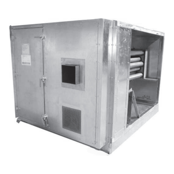
Page 7: Description
General Information Description The gas heat section consists of a drum-and-tube heat temperature limits of components in the downstream exchanger, burner, gas train components, and a control sections. panel for electrical connections. It is an integral part of the Depending on the heater size, an external vestibule that entire air-handling system. - Page 8 General Information Table 2. Vestibule locations (continued) Gas Output Vestibule Gas Output Vestibule Gas Output Vestibule Unit Size (MBh) Type Unit Size (MBh) Type Unit Size (MBh) Type 320/360 1000 1250 1500 1000 1750 1000 1250 2000 320/360 1500 2400 1750 1000 2000...
-
Page 9: Pre-Installation
Notify your Trane sales representative of the damage Hardware Kits and arrange for repair. Do not attempt to repair the unit without consulting the Trane representative. -
Page 10: Jobsite Storage
• Cover the unit securely with a canvas tarp. • Do not stack units. • Do not pile other material on the unit. Note: Trane warranty does not cover equipment damage due to negligence during storage. CLCH-SVX08C-EN... -
Page 11: Dimensions And Weights
VFDs, or other high-voltage devices must be provided per NEC requirements. For specific dimensional and weight information, refer to the unit submittals. The dimensions and weights in this manual are approximate. Trane has a policy of continuous product and product data improvement and reserves the right to change design and specifications without notice. -
Page 12: Section Dimensions And Weights
Dimensions and Weights Section Dimensions and Weights Table 4. Section dimensions (inches) and weights (pounds) - unit sizes 3-30 Unit size Height - indoor unit 29.00 29.00 35.25 37.75 37.75 41.50 41.50 49.00 52.75 61.50 Width 31.50 44.00 44.00 50.50 61.50 66.50 72.00... -
Page 13: Installation
Installation Installation Contractors’ Responsibilities WARNING Installing Contractor Improper Unit Lift! • Unpack the gas heat section and remove the skid. Do not lift unit from top! Lift unit from lifting lugs only located at bottom of unit. Test lift unit approximately 24 •... -
Page 14: Lifting And Rigging
Installation • For VAV units, provide temperature sensors for airflow required at altitude. All Trane literature is based on entering and leaving air in gas heat section. nominal outputs at sea level. Note: All power and control wiring for the gas heat It is recommended that the services of an experienced, section must be field-provided. -
Page 15: Installing Indoor Flue Stacks
Installation hood left-to-right over the inlet air opening (see Table 5. Flue connection sizes for gas heat sections Figure Gas Output (MBh) Flue Size (inches) • Install the hood to the unit with number 10 screws. 200, 320, 360, 560 8 ×... -
Page 16: Duct Connections
Installation Duct Connections airflow direction through the gas heat section are provided on the burner side of the heating section. See Figure All duct connections to the gas heat section should be Figure 10. Airflow direction label installed in accordance with the standards of the National Fire Protection Association (NFPA) and the Sheet Metal and Air Conditioning Contractors National Association, Inc. -
Page 17: Piping
Piping Figure 12. Leaving air side (tube or secondary) of gas heat section Piping • Provide adequate support for field-installed piping to avoid placing stress on the gas train and controls. WARNING • Run takeoff lines from the side or top of the main gas Hazard of Explosion and Deadly Gases! line to prevent moisture from being drawn into the gas Never solder, braze or weld on refrigerant lines or any... -
Page 18: Proper Gas Pressure
Piping • To assure sufficient gas pressure at the unit, use Figure 14. Gas heat external piping penetration appropriately sized gas pipe for unit capacity. Refer to location the National Fuel Gas Code for pipe sizing information. • Select an appropriately sized gas pressure regulator to assure the required gas supply pressure is maintained at the unit. -
Page 19: Wiring
Wiring Wiring Wiring Checklist WARNING • All field wiring must be in accordance with the National Proper Field Wiring and Grounding Electric Code and state and local requirements. Required! • All wiring (including low-voltage wiring) must be All field wiring MUST be performed by qualified copper conductors only with the insulation rated for personnel. -
Page 20: Gas Heaters With 200-1000 Mbh Output
Wiring Low-Voltage Wiring Gas Heaters with 200–1000 MBh Output Single-phase 120, 208, 230, 460 or 575 volt power is required to operate the heater controls or power the NOTICE transformer (TRANS1), if provided. Equipment Damage! Single-phase power for 208, 230 460 and 575 voltage is provided for the gas heat off two legs of the three-phase The gas heat system will not operate without a supply supply to the air-handling unit. - Page 21 Wiring Figure 16. Natural gas - 200-320 MBh - 10:1 turndown CLCH-SVX08C-EN...
- Page 22 Wiring Figure 17. Natural gas 360-1000 MBh - 3:1 and 10:1 turndown and propane 200-1000 MBh CLCH-SVX08C-EN...
- Page 23 Wiring Figure 18. Single phase natural gas and propane 1250-2000 MBh - 3:1 and 10:1 turndown CLCH-SVX08C-EN...
- Page 24 Wiring Figure 19. 3 Phase propane and natural gas 1250-2000 MBh - 3:1 and 10:1 turndown with power exhaust CLCH-SVX08C-EN...
- Page 25 Wiring Figure 20. Natural gas and propane1250-2400 MBh - 20:1 turndown CLCH-SVX08C-EN...
-
Page 26: Start Up
Start Up • Move the manual disconnect switch in the vestibule to the OFF position. WARNING • Check the air shutter and modulating gas valve Hazardous Gases and Flammable Vapors! linkages for tightness. Exposure to hazardous gases from fuel substances have •... -
Page 27: Unit Operation
Start Up removed and the correct air handling control system is Figure 22. Control panel for the FDM burner on 1250- connected. 2400 MBh (20:1 turndown) units 3. Measure the gas pressure at the tee in the pilot gas line (inlet gas pressure). -
Page 28: Main Burner Ignition
Start Up Main Burner Ignition The combustion airflow switch (CAFS1) should close, starting the purge timer, the green power light should (3:1, 10:1 Turndown, 200-2000 MBh) illuminate on the flame-relay panel, and the prepurge cycle should begin. The combustion air blower should run 1. -
Page 29: Final Check Out
Efficiency—75 percent or higher 7. Complete the start-up checklist and send a copy as c. Oxygen—8 to12 percent directed to Trane to validate the warranty. d. Carbon dioxide - 8.2 to 9.4 percent Normal Shutdown NOTICE When the system no longer requires heat, the temperature Over Firing Burners! control system opens the heat start contacts. -
Page 30: Seasonal Startup
Start Up Seasonal Startup When heating system is to be started for first time in the season: 1. Disconnect electrical power. 2. If the heat exchanger does not have a p-trap and condensate drain line, connect a hose to the drain valve and drain any accumulated condensate. -
Page 31: Heating Mode Maintenance
Routine Maintenance WARNING Hazardous Gases and Flammable Vapors! Exposure to hazardous gases from fuel substances have been shown to cause cancer, birth defects or other reproductive harm. Improper installation, adjustment, alteration, service or use of this product could cause flammable mixtures or lead to excessive carbon monoxide. - Page 32 Troubleshooting WARNING WARNING Hazardous Service Procedures! Hazardous Gases and Flammable Vapors! The maintenance and troubleshooting procedures Exposure to hazardous gases from fuel substances have recommended in this manual could result in exposure been shown to cause cancer, birth defects or other to electrical, mechanical or other potential safety reproductive harm.
- Page 33 Troubleshooting Table 11. Troubleshooting gas heat sections (continued) Symptom Probable Cause Recommended Action The manual gas valve may be closed; open it. (3:1 and 10:1 turndown burners) UV flame sensor may be dirty; check the lens for dirt, soot, and so on, and clean the lens, if necessary. Check the ignition cable and wiring for loose, frayed connections or broken wiring.
- Page 36 Our people and our family of brands—including Club Car®, Ingersoll Rand®, Thermo King® and Trane®—work together to enhance the quality and comfort of air in homes and buildings; transport and protect food and perishables; and increase industrial productivity and efficiency. We are a global business committed to a world of sustainable progress and enduring results.
Need help?
Do you have a question about the Perfomance Climate Changer CSAA Series and is the answer not in the manual?
Questions and answers