Table of Contents
Advertisement
Quick Links
MODEL G0774
AUTOMATIC EDGEBANDER
OWNER'S MANUAL
(For models manufactured since 12/23)
COPYRIGHT © FEBRUARY, 2018 BY GRIZZLY INDUSTRIAL, INC., REVISED APRIL, 2024 (JP)
WARNING: NO PORTION OF THIS MANUAL MAY BE REPRODUCED IN ANY SHAPE
OR FORM WITHOUT THE WRITTEN APPROVAL OF GRIZZLY INDUSTRIAL, INC.
#WKESJH18284 PRINTED IN TAIWAN
V5.04.24
***Keep for Future Reference***
Advertisement
Table of Contents

Related Manuals for Grizzly G0774


Summary of Contents for Grizzly G0774
- Page 1 OWNER'S MANUAL (For models manufactured since 12/23) COPYRIGHT © FEBRUARY, 2018 BY GRIZZLY INDUSTRIAL, INC., REVISED APRIL, 2024 (JP) WARNING: NO PORTION OF THIS MANUAL MAY BE REPRODUCED IN ANY SHAPE OR FORM WITHOUT THE WRITTEN APPROVAL OF GRIZZLY INDUSTRIAL, INC.
- Page 2 This manual provides critical safety instructions on the proper setup, operation, maintenance, and service of this machine/tool. Save this document, refer to it often, and use it to instruct other operators. Failure to read, understand and follow the instructions in this manual may result in fire or serious personal injury—including amputation, electrocution, or death.
-
Page 3: Table Of Contents
Table of Contents INTRODUCTION ..........2 SECTION 8: WIRING ........72 Contact Info ........... 2 Wiring Safety Instructions ......72 Manual Accuracy ........... 2 Electrical Panel Wiring Diagram ....73 Identification (Front) ........3 Electrical Panel Photos ........ 74 Identification (Rear) ........4 Terminal Block Wiring Diagram .... -
Page 4: Introduction
ID label (see below). This information is required for us to provide proper tech support, and it helps us determine if updated documenta- tion is available for your machine. Manufacture Date Serial Number Model G0774 (Mfd. Since 12/23) -
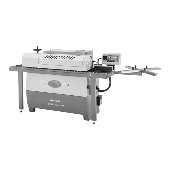
Page 5: Identification (Front)
Heated Unit Rollers Feeder Fence Coil Support Assembly Adjustable Table Air Pressure Regulator Power Connection Box Flush Trimmer Trimmer Unit Unit To reduce your risk of serious injury, read this entire manual BEFORE using machine. Model G0774 (Mfd. Since 12/23) -
Page 6: Identification (Rear)
Release Knob Glue Spindle Adjustment Knob Electrical Panel Access Doors Pneumatic Flush Lower Control Panel Trimmer Dust Port (Factory Set) Motor To reduce your risk of serious injury, read this entire manual BEFORE using machine. Model G0774 (Mfd. Since 12/23) -
Page 7: Controls & Components
Q. Adjustable Guide Rollers (4): Holds edge- E. Standby Indicator Lamp: Illuminates when banding coil in place during operation. Adjust machine is in standby mode (see Page 34). as needed according to size of coil. Model G0774 (Mfd. Since 12/23) - Page 8 Glue Flow Adjustment Knob: Rotate coun- Glue Pot: Stores and heats glue for bonding terclockwise to increase glue flow; rotate edgeband to workpiece. clockwise to decrease glue flow. U. Glue Spindle: Applies melted glue to workpiece edge. Model G0774 (Mfd. Since 12/23)
- Page 9 AC. Adjustable Pressure Roller Bolt: Loosen to — Left end trimmer blade trims trailing end of increase pressure of adjustable pressure roll- er against edgeband and workpiece. Tighten edgeband. to decrease pressure. AG. End Trimmer Tracer: Guides end trimmer blades. Model G0774 (Mfd. Since 12/23)
- Page 10 AJ. Flush Trimmer Cutters (Upper and Lower): Note: For best results, always adjust upper Rotates at approximately 10,000 RPM and and lower flush trimmer cutters equally. trims height of glued edgeband, making it flush with top and bottom of workpiece. Model G0774 (Mfd. Since 12/23)
- Page 11 AO. Panel Feeder: Uses conveyor belt to advance workpiece exits panel feeder, to allow next workpiece from infeed end of table to outfeed operation. end of table during edgebanding operation. Height is adjustable according to workpiece thickness. Model G0774 (Mfd. Since 12/23)
- Page 12 Use edgebanding tion to advance edgeband. seat adjustment knob (AX) to adjust seat according to edgebanding width. -10- Model G0774 (Mfd. Since 12/23)
- Page 13 BC. Fence Stop: Allows you to quickly and easily set the infeed fence position without having to use the scale (refer to Page 38 for details). BD. Fence Adjustment Scale: Indicates position of fence relative to edgebanding thickness in millimeter increments. -11- Model G0774 (Mfd. Since 12/23)
-
Page 14: Machine Data Sheet
Bearings .........................Shielded & Permanently Sealed Glue Spindle Horsepower ................................1/3 HP Phase ................................Single-Phase Amps ..................................1.7A Speed ................................1700 RPM Type ..........................TEFC Capacitor-Start Induction Power Transfer ................................Gear Bearings .........................Shielded & Permanently Sealed -12- Model G0774 (Mfd. Since 12/23) Model G0774 Page 1 of 3... - Page 15 Dust Collection Requirement (at Dust Port) ....................... 700 CFM Heating Element ..............................1535W (t) Table Information Work Table Length .............................78-3/4 in. Work Table Width ...............................10-1/2 in. Construction Housing ................................Aluminum Frame ..................................Steel Rollers ................................... Rubber Paint .................................Powder Coated -13- Model G0774 (Mfd. Since 12/23) Page 2 of 3 Model G0774...
- Page 16 Control Panel Controls Each Element Individually Teflon-Coated Glue Pot with 5 Heating Elements and Motorized Glue Spindle 31-1/2" Tape Coil Support Two 4-Inch Dust Ports Built-In Air Regulator and Filter for Pneumatic System -14- Model G0774 (Mfd. Since 12/23) Model G0774 Page 3 of 3...
-
Page 17: Section 1: Safety
Never operate under the influence of drugs or injury or blindness from flying particles. Everyday alcohol, when tired, or when distracted. eyeglasses are NOT approved safety glasses. -15- Model G0774 (Mfd. Since 12/23) - Page 18 EXPERIENCING DIFFICULTIES. If at any time debris. Make sure they are properly installed, you experience difficulties performing the intend- undamaged, and working correctly BEFORE ed operation, stop using the machine! Contact our operating machine. Technical Support at (570) 546-9663. -16- Model G0774 (Mfd. Since 12/23)
-
Page 19: Additional Safety For Automatic Edgebanders
Only operate this machine with proper WEAR PROPER PPE. Always wear safety glass- ventilation near work area. es, respirator, and hearing protection when oper- ating edgebander. -17- Model G0774 (Mfd. Since 12/23) -
Page 20: Section 2: Power Supply
To reduce the risk of these hazards, avoid over- loading the machine during operation and make sure it is connected to a power supply circuit that meets the specified circuit requirements. -18- Model G0774 (Mfd. Since 12/23) - Page 21 -19- Model G0774 (Mfd. Since 12/23)
-
Page 22: Section 3: Setup
IMPORTANT: Save all packaging materials until you are completely satisfied with the machine and have resolved any issues between Grizzly or the shipping agent. You MUST have the original pack- aging to file a freight claim. It is also extremely helpful if you need to return your machine later. -
Page 23: Inventory
H. Coil Support Stud Assembly ...... 1 — Stud-FT M10-1.5 x 150 ......1 Figure 13. Hardware bag contents. — Lock Nut M10-1.5 ........1 — Hex Nuts M10-1.5 ........2 — Fender Washers 10mm ......3 -21- Model G0774 (Mfd. Since 12/23) - Page 24 Figure 14. T23692 Orange Power Degreaser. Repeat Steps 2–3 as necessary until clean, then coat all unpainted surfaces with a quality metal protectant to prevent rust. -22- Model G0774 (Mfd. Since 12/23)
-
Page 25: Site Considerations
Wall = Electrical Connection Min. 30" for Maintenance 120" Feed Direction Keep Keep 84" Workpiece Workpiece Unloading Loading Area Area Unobstructed Unobstructed Figure 15. Minimum working clearances. -23- Model G0774 (Mfd. Since 12/23) -
Page 26: Lifting & Placing
Position forklift forks as wide as possible while still fitting under center opening of edge- bander cabinet (see Figure 16). Protect machine body from forks with cardboard. Figure 16. Inserting forks for lifting edgebander. -24- Model G0774 (Mfd. Since 12/23) -
Page 27: Assembly
(if applicable). Assembling the Model G0774 requires reposition- ing the control panel, installing the coil support assembly, installing the panel feeder elevation handwheel, and aligning the table extension with the table. - Page 28 (see Figure 22). Stud Coil Support Coil Support Arm Fender Hex Nut Washer Figure 24. Stud threaded into coil support arm. Figure 22. Coil support arm installed. -26- Model G0774 (Mfd. Since 12/23)
- Page 29 10mm fender washer (see Figure 26). Guide Roller Coil Support Assembly Lock Nut Slot Washer Fender Washer Slide Nut Figure 28. Guide roller installed in coil support slot. Figure 26. Coil support assembly installed. -27- Model G0774 (Mfd. Since 12/23)
- Page 30 15. Pull out extension table (see Figure 33) as far as it goes. Outfeed End Infeed End Figure 30. Location of wood shipping blocks to be removed. Figure 33. Extension table extended. -28- Model G0774 (Mfd. Since 12/23)
-
Page 31: Dust Collection
Table Leg Jam Nut Adjustable Adjustable Foot Nut Foot Figure 35. Location of extension table alignment components. Figure 36. Dust hoses attached to dust ports. 18. Repeat Steps 16–17 for outfeed (left) end of table. -29- Model G0774 (Mfd. Since 12/23) -
Page 32: Test Run
Figure 38. Thermoregulator display illuminated assembly steps in this manual have been after master power switch turned ON. followed and completed. -30- Model G0774 (Mfd. Since 12/23) - Page 33 (410°F). To avoid serious burns, DO NOT Figure 41. Upper and lower green ON/OFF touch fence while it is turned ON or while buttons, OFF button, and Emergency Stop still hot after being turned OFF. button. -31- Model G0774 (Mfd. Since 12/23)
- Page 34 Tech Support for help. switch OFF and disconnect machine from power. The Emergency Stop button safety feature is not working correctly. This safety feature must work correctly before proceeding with regular operations. Call Tech Support for help. -32- Model G0774 (Mfd. Since 12/23)
-
Page 35: Section 4: Operations
13. When finished, stops machine, turns it OFF, ects. Regardless of the content in this sec- and disconnects it from power. tion, Grizzly Industrial will not be held liable for accidents caused by lack of training. -33- Model G0774 (Mfd. Since 12/23) -
Page 36: Machine Startup
E. Cycle Up Button: Press once, when con- trol panel is in temperature edit mode, to increase value of flashing digit by one; press again until desired number is reached. -34- Model G0774 (Mfd. Since 12/23) -
Page 37: Checking/Adding Glue
G. Glue Spindle Power Indicator (AL1): The G0774 uses a glue pot system that melts Illuminates when power to glue spindle motor glue pellets and dispenses the melted glue using is active. -
Page 38: Installing Edgebanding Coil
The Model G0774 uses edgebanding tape from ⁄ "–1 ⁄ " wide. - Page 39 Nylon Roller nylon roller with one layer of duct tape to Release Knob increase grip. Figure 46. Edgebanding tape advanced to forward end of edgebanding seat (viewed from rear of machine). -37- Model G0774 (Mfd. Since 12/23)
-
Page 40: Adjusting Infeed Fence
Loosen infeed fence adjustment lock lever, rotate knurled cylinder until number indicating thickness of edgebanding aligns with mark on scale (see Figure 48), then retighten lock lever. -38- Model G0774 (Mfd. Since 12/23) -
Page 41: Adjusting Guide Plate
Close panel feeder. — If workpiece is more than 0.5mm away or touches glue spindle, the guide plate is not properly adjusted. Proceed to Step 7. -39- Model G0774 (Mfd. Since 12/23) -
Page 42: Adjusting Glue Flow
0.5mm away from glue spindle. Glue Flow Adjustment Note: When guide plate is properly adjusted, Knob workpiece will pull glue off without touching spindle. Close panel feeder. Figure 53. Location of glue flow adjustment knob. -40- Model G0774 (Mfd. Since 12/23) -
Page 43: Adjusting Panel Feeder Height
3–4 digits, then raise back up to eliminate backlash in worm gear. Handwheel Numerical Readouts Adjustment Numerical Knobs Display Figure 55. Panel feeder elevation handwheel. Figure 56. Flush trimmer adjustment knobs. -41- Model G0774 (Mfd. Since 12/23) -
Page 44: Performing Edgebanding Operation
When glue pot reaches 180°C, glue spindle motor will start (see Figure 57). Any workpiece you intend to edgeband with the G0774 must have at least one straight and square edge that is at least 9 ⁄ " long. - Page 45 11. Receive edgebanded workpiece at outfeed (see Figure 59). end of table. Allow panel feeder to com- pletely finish feeding workpiece, then remove workpiece from table. -43- Model G0774 (Mfd. Since 12/23)
-
Page 46: Section 5: Accessories
T26419—Syn-O-Gen Synthetic Grease cause machine to malfunction, resulting in serious personal injury or machine damage. To reduce this risk, only install accessories T26685 recommended for this machine by Grizzly. NOTICE T26419 Refer to our website or latest catalog for additional recommended accessories. - Page 47 Table size: 31 ⁄ "W x 17"D x 11 ⁄ "H. Figure 64. T1189 Dual End Cutter for G0825. Figure 66. T1187 Stationary Work Table for G0825. www.grizzly.com 1-800-523-4777 order online at or call -45- Model G0774 (Mfd. Since 12/23)
-
Page 48: Section 6: Maintenance
Cleaning & maintenance, or service. Protecting Schedule Cleaning the Model G0774 is extremely impor- tant and is the first step to keeping your machine For optimum performance from this machine, this functioning properly. Cleaning the Model G0774 maintenance schedule must be strictly followed. -
Page 49: Lubrication
Manually move motor back and forth and up and down to evenly distribute the oil along the sliders. Figure 68. Location of end trimmer motor sliders. -47- Model G0774 (Mfd. Since 12/23) - Page 50 -48- Model G0774 (Mfd. Since 12/23)
-
Page 51: Section 7: Service
7. Pulley/sprocket slipping on shaft. 7. Replace loose pulley/shaft. 8. Centrifugal switch at fault. 8. Adjust/replace centrifugal switch if available. 9. Motor bearings at fault. 9. Test by rotating shaft; rotational grinding/loose shaft requires bearing replacement. -49- Model G0774 (Mfd. Since 12/23) - Page 52 3. Heater rods at fault. 3. Inspect heater rod connections; tighten if necessary. Test heater rod amperage (top: 315W, 1.0A; lower large: 250W, 0.9A; lower small: 160W, 0.6A); replace if necessary. -50- Model G0774 (Mfd. Since 12/23)
- Page 53 2. Inspect/replace knives (Page 67). operation. Cutterheads will not 1. Debris stuck between cylinder and housing. 1. Lubricate flush trimmer shafts to free up movement. adjust in or out. 2. Burrs preventing movement. 2. Remove cylinder, inspect/clean and lightly sand both surfaces, then re-install cylinder. -51- Model G0774 (Mfd. Since 12/23)
- Page 54 2. Panel feeder not exerting enough 2. Adjust panel feeder pressure (Page 54). finished workpiece. downward force on workpiece. Ends not cleanly 1. End trimmer saw blades dull. 1. Sharpen/replace end trimmer saw blades cut. (Page 61). -52- Model G0774 (Mfd. Since 12/23)
-
Page 55: Adjusting Panel Feeder
Proceed to Step 4. Tension Screws Figure 73. Location of conveyor belt tension screws. Repeat Steps 3–4, as necessary, until con- veyor belt is properly tensioned. Close and lock panel feeder. -53- Model G0774 (Mfd. Since 12/23) - Page 56 (see Figure 75. Dial indicator adjustment Figure 74). components. Raise panel feeder and remove test workpiece. Workpiece Under Panel Feeder Figure 74. Panel feeder lowered to workpiece. -54- Model G0774 (Mfd. Since 12/23)
-
Page 57: Calibrating Infeed Fence Scale
Infeed fence scale is now calibrated. Check fence scale (see Figure 76). Lock Lever Fence Scale Stop Plate Jam Nut Stop Bolt Figure 76. Infeed fence stop components. -55- Model G0774 (Mfd. Since 12/23) -
Page 58: Removing/Changing Glue
Use wood stick to peel up one side of glue, as er amount of glue (refer to Checking/Adding shown in Figure 77. Glue on Page 35). At 80°–90°C, Glue Peels Away From Glue Pot Figure 77. Using wood stick to peel glue away. -56- Model G0774 (Mfd. Since 12/23) -
Page 59: Adjusting Pressure Roller Unit
Items Needed Open-End Wrench 10mm ........1 Test workpiece at Least 35" Long ..... 1 Glue Infeed Approx. 0.040" Spindle Fence (1mm) Gap Figure 81. Workpiece placed against infeed fence and pressure roller unit. -57- Model G0774 (Mfd. Since 12/23) - Page 60 13. If necessary, repeat Steps 1–12. -58- Model G0774 (Mfd. Since 12/23)
-
Page 61: End Trimmers
Adjusting Drive Belt Tension ....Page 62 Replacing Drive Belt ......Page 64 Adjusting Tracers Items Needed Hex Wrench 3mm ..........1 Figure 86. Workpiece placed on infeed table. Test workpiece at Least 35" Long ..... 1 -59- Model G0774 (Mfd. Since 12/23) - Page 62 — If blade is aligned to tracer, then no adjust- Repeat Steps 1–7 until satisfied with results. ment is necessary. — If blade is not aligned with tracer, then tracer must be adjusted. Proceed to Step 5. -60- Model G0774 (Mfd. Since 12/23)
- Page 63 Removing Bolt Wood Block Supporting Raised Figure 92. Removing end trimmer blades with End Trimmer Unit dust shroud removed. Figure 90. End trimmer unit raised and supported with wood block for access to blades. -61- Model G0774 (Mfd. Since 12/23)
- Page 64 IMPORTANT: Make sure to orient compo- remove cover (see Figure 94). nents (see Figure 93) in same direction as they were before removal. Belt Cover Figure 94. Location of belt cover cap screws. -62- Model G0774 (Mfd. Since 12/23)
- Page 65 Pulley Approx. ” Adjustment Hole Deflection Pulley Figure 96. End trimmer belt deflection. Motor Mount Cap Screw Figure 98. Loosening one of four end trimmer motor mount cap screws. -63- Model G0774 (Mfd. Since 12/23)
- Page 66 10. Check belt deflection again and, if necessary, re-adjust it, then tighten remaining motor mount cap screws from Steps 6–8. 11. Tighten cap screws from Step 5, then install belt cover, and close rear access cover. -64- Model G0774 (Mfd. Since 12/23)
-
Page 67: Flush Trimmers
Before making any adjustments, ensure all parts are clean and free of debris, glue, and residue. Adjusting Cutterhead Alignment ..Page 65 Calibrating Adjustment Knobs ..Page 66 Replacing Cutterhead Knives .....Page 67 Replacing Drive Belt ......Page 68 -65- Model G0774 (Mfd. Since 12/23) -
Page 68: Calibrating Adjustment Knobs
Rotate collar until it reads the measurement enough chamfer on the top and bottom of the of edgebanding from Step 1. workpiece. By calibrating the adjustment knobs, the in/out position of the cutterhead is being Tighten set screw. adjusted. -66- Model G0774 (Mfd. Since 12/23) -
Page 69: Replacing Cutterhead Knives
Repeat Steps 3–4 with remaining knives on cutterhead. If necessary, repeat Steps 3–5 with knives of other cutterhead. Block Close and lock panel feeder. Knife (1 of 4) Screw Figure 105. Upper flush trimmer knife components. -67- Model G0774 (Mfd. Since 12/23) -
Page 70: Replacing Drive Belt
Lower panel feeder all the way, then open rear access cover. Loosen cap screw shown in Figure 108. Figure 110. Flush trimmer drive belt properly routed around pulleys. Figure 108. Location of adjustment bracket cap screw. -68- Model G0774 (Mfd. Since 12/23) -
Page 71: Adjusting/Replacing Buffing Wheels
If the buffing wheels fail to produce smooth, pol- locations. ished upper and lower edges, the wheels may need to be adjusted. Lower motor so buffing wheel just bare- ly touches workpiece, then tighten motor mounting bolts. -69- Model G0774 (Mfd. Since 12/23) - Page 72 (see Figure 114). Bolt has left-hand on Page 69. threads (clockwise to loosen; counterclock- wise to tighten). Note: If arbor spins, secure it by inserting a 5mm hex wrench into arbor cap screw. -70- Model G0774 (Mfd. Since 12/23)
-
Page 73: Adjusting Limit Switches
Limit Switch and not enough on leading end, move switch toward outfeed table, then tighten Figure 115. Location of guillotine limit switch and adjustment screws. adjustment screws. -71- Model G0774 (Mfd. Since 12/23) -
Page 74: Section 8: Wiring
Technical Support at (570) 546-9663. The photos and diagrams included in this section are best viewed in color. You can view these pages in color at www.grizzly.com. -72- Model G0774 (Mfd. Since 12/23) -
Page 75: Electrical Panel Wiring Diagram
Electrical Panel Wiring Diagram READ ELECTRICAL SAFETY -73- Model G0774 (Mfd. Since 12/23) ON PAGE 72! -
Page 76: Electrical Panel Photos
Conveyor Motor Glue Spindle Motor End Trimmer Motor Flush Trimmer Motor Upper Buffing Motor Glue Pot Heater Warm-Up Heater Figure 121. Contactor/overload legend. Figure 119. Electrical panel detail—left side. READ ELECTRICAL SAFETY -74- Model G0774 (Mfd. Since 12/23) ON PAGE 72! -
Page 77: Terminal Block Wiring Diagram
Terminal Block Wiring Diagram READ ELECTRICAL SAFETY -75- Model G0774 (Mfd. Since 12/23) ON PAGE 72! -
Page 78: Motor Wiring Diagram
Glue Spindle Motor 220V 1-Phase Conveyor Motor 220V 1-Phase Upper Buffing Motor 220V 1-Phase Flush Trimmer Motor 220V 1-Phase Lower Buffing Motor 220V 1-Phase End Trimmer Motor 220V 1-Phase READ ELECTRICAL SAFETY -76- Model G0774 (Mfd. Since 12/23) ON PAGE 72! -
Page 79: Motor Photos
Figure 125. Conveyor motor wiring. Figure 123. Upper buffing motor wiring. Figure 126. Flush trimmer motor wiring. Figure 124. Lower buffing motor wiring. Figure 127. End trimmer motor wiring. READ ELECTRICAL SAFETY -77- Model G0774 (Mfd. Since 12/23) ON PAGE 72! -
Page 80: Control Panel Wiring Diagram
Control Panel Wiring Diagram READ ELECTRICAL SAFETY -78- Model G0774 (Mfd. Since 12/23) ON PAGE 72! - Page 81 Control Panel SEB-E330 Component Key Relay Contact Postion Control Panel SEB-E330 (Standby Mode) READ ELECTRICAL SAFETY -79- Model G0774 (Mfd. Since 12/23) ON PAGE 72!
-
Page 82: Pneumatic Valve & Limit Switch Wiring Diagram
Pneumatic Valve & Limit Switch Wiring Diagram Cutter Trimmer End Trimmer Limit Switch Limit Switch Door Door Limit Switch Limit Switch Pressure Switch READ ELECTRICAL SAFETY -80- Model G0774 (Mfd. Since 12/23) ON PAGE 72! -
Page 83: Electrical Schematics
12(com1) Brown 0(Blue) Front & End Trimming Cylinder Move Down (EV4 Solenoid Valve) Flush Trimming Motor On Indicator Light for Flush Trimming Motor PLC com C0,C1,C2 connect12 C3connect1 READ ELECTRICAL SAFETY -81- Model G0774 (Mfd. Since 12/23) ON PAGE 72! - Page 84 Power Supply—Main Control Circuit Main Control Circuit READ ELECTRICAL SAFETY -82- Model G0774 (Mfd. Since 12/23) ON PAGE 72!
- Page 85 Power Supply—Motor Circuit Breaker Motor Ciruit Breaker READ ELECTRICAL SAFETY -83- Model G0774 (Mfd. Since 12/23) ON PAGE 72!
- Page 86 Power Supply—Transformer & Heater Transformer & Heater READ ELECTRICAL SAFETY -84- Model G0774 (Mfd. Since 12/23) ON PAGE 72!
- Page 87 Power Supply—PLC Input PLC Input READ ELECTRICAL SAFETY -85- Model G0774 (Mfd. Since 12/23) ON PAGE 72!
- Page 88 Power Supply—PLC Output PLC Output READ ELECTRICAL SAFETY -86- Model G0774 (Mfd. Since 12/23) ON PAGE 72!
-
Page 89: Section 9: Pneumatic System
SECTION 9: PNEUMATIC SYSTEM This diagram is only provided as a reference to help you identify pneumatic system components. Seek assistance from a professional pneumatic technician when- ever servicing or repairing the pneumatic system. -87- Model G0774 (Mfd. Since 12/23) -
Page 90: Section 10: Parts
SECTION 10: PARTS We do our best to stock replacement parts when possible, but we cannot guarantee that all parts shown are available for purchase. Call (800) 523-4777 or visit www.grizzly.com/parts to check for availability. Parts Reference Page Panel Feeder Elevation... -
Page 91: Main Table
Main Table 69AV2 69V2 29-1 36-1 -89- BUY PARTS ONLINE AT GRIZZLY.COM! Model G0774 (Mfd. Since 12/23) Scan QR code to visit our Parts Store. - Page 92 36-1 P07740036-1 CORD 3W 12G 16" P07740078 POWER CORD 12G 3W 10' L6-30P P07740037 SWITCH BOX P07740079 TERMINAL BLOCK 4P P07740038 EXTENSION BRACKET BLOCK -90- BUY PARTS ONLINE AT GRIZZLY.COM! Model G0774 (Mfd. Since 12/23) Scan QR code to visit our Parts Store.
-
Page 93: Pressure Regulator Assembly
ELBOW FITTING 1/8 X 6 90DEG 28V2-4 P07740028V2-4 REGULATOR PLATE 28V2-10 P07740028V2-10 REGULATOR 1/8" FONRAY ASC-01 G1/8" 28V2-5 P07740028V2-5 REGULATOR 1/4" FONRAY RE-02 G1/4" -91- BUY PARTS ONLINE AT GRIZZLY.COM! Model G0774 (Mfd. Since 12/23) Scan QR code to visit our Parts Store. -
Page 94: Control Panel
71-1 P07740071-1 TEMPERATURE CONTROLLER FOTEK NT-72RE 71-5 P07740071-5 STANDBY LIGHT FUJI AH164-ZRE3 16MM 71-2 P07740071-2 CONTROL PANEL LABEL 71-6 P07740071-6 E-STOP BUTTON REMY R2PNR4-1B-R 22MM -92- BUY PARTS ONLINE AT GRIZZLY.COM! Model G0774 (Mfd. Since 12/23) Scan QR code to visit our Parts Store. -
Page 95: Cover Panels
P07740116 TOP COVER P07740134 FLAT WASHER 5MM P07740117 FLANGE NUT M8-1.25 P07740135 FRONT COVER (LOWER) P07740118 CAP SCREW M8-1.25 X 16 -93- BUY PARTS ONLINE AT GRIZZLY.COM! Model G0774 (Mfd. Since 12/23) Scan QR code to visit our Parts Store. -
Page 96: Panel Feeder Elevation
P07740217 COLUMN P07740236 FLAT HD CAP SCR M8-1.25 X 12 P07740218 CAP SCREW M5-.8 X 45 P07740237 SET SCREW M5-.8 X 6 -94- BUY PARTS ONLINE AT GRIZZLY.COM! Model G0774 (Mfd. Since 12/23) Scan QR code to visit our Parts Store. -
Page 97: Panel Feeder
BALL BEARING 6202ZZ (REAR) P07740346 BUTTON HD CAP SCR M5-.8 X 10 319-10 P07740319-10 S CAPACITOR 150MFD 250V P07740347 FLAT WASHER 4MM -95- BUY PARTS ONLINE AT GRIZZLY.COM! Model G0774 (Mfd. Since 12/23) Scan QR code to visit our Parts Store. -
Page 98: Panel Feeder Lock
P07740410 FLAT WASHER 8MM P07740421 WAVY WASHER 10MM P07740411 ADJUSTMENT BRACKET P07740422 FLAT WASHER 10MM P07740412 DOOR SWITCH MOUNTING PLATE P07740423 LOCK BRACKET BLOCK -96- BUY PARTS ONLINE AT GRIZZLY.COM! Model G0774 (Mfd. Since 12/23) Scan QR code to visit our Parts Store. -
Page 99: Pneumatic Guillotine
P07740521 CAP SCREW M6-1 X 20 P07740510 FLAT HD CAP SCR M6-1 X 12 P07740522 FENDER WASHER 6MM P07740511 CAP SCREW M6-1 X 35 -97- BUY PARTS ONLINE AT GRIZZLY.COM! Model G0774 (Mfd. Since 12/23) Scan QR code to visit our Parts Store. -
Page 100: Flush Trimmer Motor
611-8 P07740611-8 BALL BEARING 6203ZZ (FRONT) P07740630 SET SCREW M6-1 X 20 611-9 P07740611-9 BALL BEARING 6202ZZ (REAR) P07740631 INT RETAINING RING R21 -98- BUY PARTS ONLINE AT GRIZZLY.COM! Model G0774 (Mfd. Since 12/23) Scan QR code to visit our Parts Store. -
Page 101: Coil Support
P07740707 STUD-FT M10-1.5 X 150 P07740717 BEARING SPACER P07740708 BUTTON HD CAP SCR M8-1.25 X 16 P07740718 LOCK NUT M10-1.5 P07740709 FLAT WASHER 8MM -99- BUY PARTS ONLINE AT GRIZZLY.COM! Model G0774 (Mfd. Since 12/23) Scan QR code to visit our Parts Store. -
Page 102: Edgebanding Intake Assembly
P07740803 SHOULDER BOLT M5-.8 X 8, 8 X 18 P07740808 FLAT WASHER 6MM P07740804 KNOB 4-LOBE M5-.8 P07740809 CAP SCREW M6-1 X 10 -100- BUY PARTS ONLINE AT GRIZZLY.COM! Model G0774 (Mfd. Since 12/23) Scan QR code to visit our Parts Store. -
Page 103: Pressure Roller
P07740933 FLAT WASHER 6 X 18 X 2MM P07740916 COMPRESSION SPRING 2.5 X 14 X 30 P07740934 SET SCREW M8-1.25 X 8 P07740917 FLAT WASHER 6MM -101- BUY PARTS ONLINE AT GRIZZLY.COM! Model G0774 (Mfd. Since 12/23) Scan QR code to visit our Parts Store. -
Page 104: Heated Fence
1020 P07741020 ADJUSTABLE HANDLE M8-1.25, 82L 1010 P07741010 HEX BOLT M8-1.25 X 12 1021 P07741021 FENDER WASHER 8 X 30 X 3MM -102- BUY PARTS ONLINE AT GRIZZLY.COM! Model G0774 (Mfd. Since 12/23) Scan QR code to visit our Parts Store. -
Page 105: Edgebanding Feeder
1145 P07741145 FENDER WASHER 8 X 23 X 2MM 1122 P07741122 HEX NUT M6-1 LH 1146 P07741146 HEX NUT M8-1.25 1123 P07741123 HEX NUT M8-1.25 -103- BUY PARTS ONLINE AT GRIZZLY.COM! Model G0774 (Mfd. Since 12/23) Scan QR code to visit our Parts Store. -
Page 106: End Trimmer Carriage
1223 P07741223 HORIZONTAL AIR CYLINDER SMC-16N150 1251 P07741251 FLAT WASHER 6MM 1225 P07741225 CAP SCREW M8-1.25 X 20 1252 P07741252 FLAT WASHER 8MM -104- BUY PARTS ONLINE AT GRIZZLY.COM! Model G0774 (Mfd. Since 12/23) Scan QR code to visit our Parts Store. -
Page 107: End Trimmer Motor
P07741345 KEY 4 X 4 X 20 1319 P07741319 BLADE SPACER 1346 P07741346 SET SCREW M5-.8 X 5 1320 P07741320 FLANGE -105- BUY PARTS ONLINE AT GRIZZLY.COM! Model G0774 (Mfd. Since 12/23) Scan QR code to visit our Parts Store. -
Page 108: Vertical Edgebanding Guide & Glue Spindle
1420 P07741420 FLAT WASHER 4MM 1517 P07741517 GEAR 21T 1421 P07741421 LOCK WASHER 4MM 1518 P07741518 SET SCREW M6-1 X 8 -106- BUY PARTS ONLINE AT GRIZZLY.COM! Model G0774 (Mfd. Since 12/23) Scan QR code to visit our Parts Store. -
Page 109: Glue Pot Cover
1622 P07741622 LOCK WASHER 6MM 1647 P07741647 SET SCREW M6-1 X 12 1623 P07741623 FENDER WASHER 6 X 19 X 2 -107- BUY PARTS ONLINE AT GRIZZLY.COM! Model G0774 (Mfd. Since 12/23) Scan QR code to visit our Parts Store. -
Page 110: Glue Pot
1726 P07741726 CORD 14G 2W 24" 1716 P07741716 CAP SCREW M6-1 X 50 1728 P07741728 BUTTON HD CAP SCR M4-.7 X 8 -108- BUY PARTS ONLINE AT GRIZZLY.COM! Model G0774 (Mfd. Since 12/23) Scan QR code to visit our Parts Store. -
Page 111: Glue Spindle Motor
MOTOR CORD 16G 3W 18" 1822-2 P07741822-2 MOTOR FAN 1841 P07741841 BUTTON HD CAP SCR M6-1 X 8 1822-4 P07741822-4 R CAPACITOR 20MFD 250V -109- BUY PARTS ONLINE AT GRIZZLY.COM! Model G0774 (Mfd. Since 12/23) Scan QR code to visit our Parts Store. -
Page 112: Upper & Lower Buffing Motors
FLAT WASHER 22 X 55 X 3MM 1919 P07741919 MOTOR CORD 16G 3W 36" 2020 P07742020 MOTOR CORD 16G 3W 24" -110- BUY PARTS ONLINE AT GRIZZLY.COM! Model G0774 (Mfd. Since 12/23) Scan QR code to visit our Parts Store. -
Page 113: Upper Flush Trimmer
FLAT HD CAP SCR M4-.7 X 8 2129 P07742129 SPRING PLATE 2156 P07742156 SET SCREW M5-.8 X 8 2130 P07742130 MOUNTING BLOCK -111- BUY PARTS ONLINE AT GRIZZLY.COM! Model G0774 (Mfd. Since 12/23) Scan QR code to visit our Parts Store. -
Page 114: Lower Flush Trimmer
2225 P07742225 BUTTON HD CAP SCR M5-.8 X 8 2249 P07742249 FLANGE BOLT M6-1 X 12 2226 P07742226 FLAT HD CAP SCR M5-.8 X 8 -112- BUY PARTS ONLINE AT GRIZZLY.COM! Model G0774 (Mfd. Since 12/23) Scan QR code to visit our Parts Store. -
Page 115: Electrical Panel
2325 P07742325 MOUNTING RAIL 1-3/8 X 1-3/8 X 17-1/4" 2313 P07742313 OL RELAY SHIHLIN MR-32S-6.3 4-6.3A 2326 P07742326 MOUNTING RAIL 1-3/8 X 1-3/8 X 12-1/4" -113- BUY PARTS ONLINE AT GRIZZLY.COM! Model G0774 (Mfd. Since 12/23) Scan QR code to visit our Parts Store. -
Page 116: Labels & Cosmetics
Safety labels help reduce the risk of serious injury caused by machine hazards. If any label comes off or becomes unreadable, the owner of this machine MUST replace it in the original location before resuming operations. For replacements, contact (800) 523-4777 or www.grizzly.com. -114- BUY PARTS ONLINE AT GRIZZLY.COM! - Page 117 Safety labels help reduce the risk of serious injury caused by machine hazards. If any label comes off or becomes unreadable, the owner of this machine MUST replace it in the original location before resuming operations. For replacements, contact (800) 523-4777 or www.grizzly.com. -115- BUY PARTS ONLINE AT GRIZZLY.COM!
-
Page 119: Warranty & Returns
WARRANTY & RETURNS Grizzly Industrial, Inc. warrants every product it sells for a period of 1 year to the original purchaser from the date of purchase. This warranty does not apply to defects due directly or indirectly to misuse, abuse, negligence, accidents, repairs or alterations or lack of maintenance. This is Grizzly’s sole written warranty...
Need help?
Do you have a question about the G0774 and is the answer not in the manual?
Questions and answers