Table of Contents
Advertisement
Quick Links
th
March 11
, 2022
Dynabook Laptop Components Classified as Requiring Selective Treatment
Dynabook would like to communicate the method of identifying and removing components
contained in Dynabook notebook products, including but not limited to the Dynabook
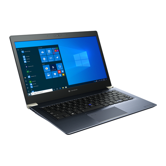
Portege X40-G
model, that requires selective treatment based on the European WEEE
Directive, Directive 2012/19/EU of the European Parliament and of the Council on waste
electrical and electronic equipment (WEEE).
All of the instructions provided within this letter can be reviewed in greater detail within the
Portege X40-G
Series Maintenance Manual.
Tools Required
In order to remove internal components of the
may be required located in Chapter 4 Replacement Procedures of the Dynabook
Maintenance Manual
Table of Contents
• (Page 2-3) Removing the Lithium Ion Battery (Main Battery, No
coin cell battery)
• (Page 4-5) Removing the SSD
• (Page 6-7) LCD, Printed Circuit / Wiring Boards (PCB/ PWB system
board)
• (Page 7) AC Adapter and external provide cable
Portege X40-G
some tools from the list below
Advertisement
Table of Contents

Related Manuals for dynabook Portege X40-G


Summary of Contents for dynabook Portege X40-G
- Page 1 March 11 , 2022 Dynabook Laptop Components Classified as Requiring Selective Treatment Dynabook would like to communicate the method of identifying and removing components contained in Dynabook notebook products, including but not limited to the Dynabook Portege X40-G model, that requires selective treatment based on the European WEEE Directive, Directive 2012/19/EU of the European Parliament and of the Council on waste electrical and electronic equipment (WEEE).
- Page 2 Please refer to the information below for instructions regarding the identification and removal of the lithium ion battery. Further maintenance instructions can be found in section 4.5 of the Portege X40-G Maintenance Manual. Some tools are required in order to remove this component.
- Page 3 Figure 4-5 Removing the Base Assembly (2) Base assembly Cover Assembly Latch 4.12 Battery pack 4.12.1 Removing the Battery pack To remove the battery pack, follow the steps below and refer to Figure 4-6. Take care not to short circuit the terminals when removing the battery pack.
- Page 4 2. Removing the SSD To remove the SSD the mainboard must be removed first. Please refer to the information listed in section 4.22 of the Portege X40-G Series Maintenance Manual to check how the mainboard is removed. Please refer to the information below for the removal of the SSD.
- Page 5 1. Remove the following screw and disconnect the SSD from the connector CN1910 on the SYSTEM board. Figure 4-32 Removing the SSD S2x3BT CN1910...
- Page 6 3. Removing the LCD and Printed Circuit / Wiring Boards Beside the LCD and the main PCB, there are further small PCBs and components which are in the scope of the WEEE Directive. The removal of these components is described in detail in the chapter 4 of the associated maintenance manual.
-
Page 8: Removing The Cover Assembly And Base Assembly
4.11 Cover Assembly and Base Assembly 4.11.1 Removing the Cover Assembly and Base Assembly To remove the Base Assembly, follow the steps below and refer to Figure 4- Figure 4-5. 1. Close the display panel and turn the computer face down. 2. -
Page 9: Removing The Battery Pack
Figure 4-5 Removing the Base Assembly (2) Base assembly Cover Assembly Latch 4.11.2 Installing the Base Assembly To install the Base Assembly, follow the steps below and refer to Figure 4-4 Figure 4-5. 1. Set the Cover Assembly on the Base Assembly while securing the latch. -
Page 10: Installing The Battery Pack
Dispose always the used battery pack in accordance with the laws and ordinances of your local authority. Use only the batteries approved by Dynabook. Check the battery’s terminals visually. If they are dirty, wipe them clean with a dry cloth. -
Page 11: Installing The Memory Module
Do not touch the connectors on the memory module or on the computer. Dust or stains on the connectors may cause memory access problems. Never press hard or bend the memory module. 1. Open the left and right latches outside and remove the memory module(s). -
Page 12: Smart Card Slot
Figure 4-8 Seating the memory module After installing the memory module, make sure that the memory module is secured with the left and right latches. 4.14 Smart Card slot 4.14.1 Removing the Smart Card slot To remove the Smart Card slot unit, follow the steps below and refer to Figure 4-9 Figure 4-10. - Page 13 Figure 4-9 Removing the Smart Card slot (1) 2170 S2x2BT Smart Card slot Smart Card slot 3. Disconnect the Smart Card slot FFC from the connector on the Smart Card slot. Figure 4-10 Removing the Smart Card slot (2) 4.14.2 Installing the Smart Card slot To install the Smart Card slot, follow the steps below and refer to Figure 4-9...
- Page 14 4.15 LED board (FUR3LE*) 4.15.1 Removing the LED board (FUR3LE*) To remove the board, follow the steps below and refer to Figure 4-11. 1. Disconnect the LED board (FUR3LE*) FFC from the connector CN9570 on the System Board (FUR3SY*). 2. Remove the following screws securing the LED board (FUR3LE*) and remove the board.
-
Page 15: Removing The Speaker
4.16 Speaker 4.16.1 Removing the Speaker To remove the Speaker, follow the steps below and refer to Figure 4-12 Figure 4-16. 1. Disconnect the Click Pad FFC and Fingerprint FFC from the connector on the Click Pad and the connector CN9560 and CN9550 on the System Board. - Page 16 Figure 4-14 Removing the Speaker (3) INSU KB FPC 4. Disconnect the Speaker harness from the connector CN6000 on the system board. 5. Open the INSU and stick tape. Release the Speaker harness from the guides. Figure 4-15 Removing the Speaker (4) CN6000 Speaker harness 6.
-
Page 17: Installing The Speaker
Figure 4-16 Removing the Speaker (5) SH2x2.5CT Speaker Speaker 4.16.2 Installing the Speaker To install the Speaker, follow the steps below. 1. Set the speakers to the slots of the Cover Assembly and secure it with the screws. 2. Arrange the Speaker harness under the guides as shown below, and fix it with the new INSU. - Page 18 7. Connect the Click Pad FFC and Fingerprint FFC to the connector on the Click Pad and the connector CN9560 and CN9550 on the System Board. 4.17 Dual button unit 4.17.1 Removing the dual button unit To remove the dual button unit, follow the steps below and refer to Figure 4- Figure 4-20.
- Page 19 Figure 4-20 Removing the dual button (3) Dual button 4.17.2 Installing the dual button unit To install the dual button unit, follow the steps below and refer to Figure 4- Figure 4-20. 1. Set the Dual button to the Cover Assembly. 2.
- Page 20 Figure 4-21 Removing the 3G module (1) 3. Remove the following screw and disconnect the 3G MODULE from the connector CN2610 on the USB board (FUR3CN*). Figure 4-22 Removing the 3G module (2) S2x3BT 3G MODULE CN2610 4. Disconnect the FPC (FMR3YC*) from the connector CN9510 on the SYSTEM board and CN9800 on the USB board.
- Page 21 Figure 4-23 Removing the USB board (1) CN9800 CN9510 FPC (FMR3YC*) 5. Remove the following screws and the USB board from the Cover Assembly. Figure 4-24 Removing the USB board (2) S2x3CT 4.18.2 Installing the 3G module/USB board To install the 3G module/USB board (FUR3CN*), follow the steps below and refer to Figure 4-21 Figure...
-
Page 22: Removing The Wireless Lan Card
6. Stick an insulator to secure 3G ANTENNA cables and camera harness in place. 4.19 Wireless LAN card 4.19.1 Removing the Wireless LAN card To remove the Wireless LAN card, follow the steps below and refer to Figure 4-25. 1. Peel off the INSU WL. 2. -
Page 23: Removing The Fan
4. Connect the Wireless LAN antenna cables to the connectors (black cable to “AUX” or “1” and white cable to “Main” or “2”) on the Wireless LAN card. Figure 4-26 Arranging Wireless LAN antenna cable 5. Stick a new INSU WL in place. 4.20 Fan 4.20.1 Removing the Fan... -
Page 24: Installing The Fan
Figure 4-27 Removing the Fan S2 x 3CT Fan harness CN3380 4.20.2 Installing the Fan To install the Fan, follow the steps below and refer to Figure 4-27. 1. Set the Fan in place on the Cover Assembly and secure it with the screws. -
Page 25: System Board
Figure 4-28 Removing the Fin B2 x 2.5CT When removing the Fin, be sure to remove the screws in the reverse order of the number marked on the Fin. 4.21.2 Installing the Fin To install the Fin, follow the steps below and refer to Figure 4-28. -
Page 26: Removing The System Board
When replacing the system board with a new one, stick a new INSU BOSS on one side of the system board in place. INSU BOSS When replacing the system board with a new one, stick two pieces of new COOL SHEET (GY4C00073D10 and GY4C00073E10) and three pieces of new GUM CUSHION on the other side of the system board in place. - Page 27 Figure 4-29 Removing the system board (1) 3. Disconnect the camera harness from the connector CN9540 on system board. 4. Disconnect the LCD harness from the connector CN5930 on the System Board (FUR3SY*). Figure 4-30 Removing the system board (2) CN5930 5.
-
Page 28: Installing The System Board
Figure 4-31 Removing the system board (3) S2 x 3CT 4.22.2 Installing the System board To install the system board, follow the steps below and refer to Figure 4-29 Figure 4-31. 1. Set the system board in place. 2. Secure the system board with the screws. 3. -
Page 29: Installing The Ssd
Take care not to press on the top or bottom of a SSD. Pressure may cause the data loss or damage to the device. 1. Remove the following screw and disconnect the SSD from the connector CN1910 on the SYSTEM board. Figure 4-32 Removing the SSD S2x3BT CN1910... -
Page 30: Removing The Power Button
Figure 4-33 Installing the SSD CN1910 S2x3BT 4.24 Power button 4.24.1 Removing the Power button To remove the Power button, follow the steps below and refer to Figure 4- 1. Release the latch from the slot on the Cover Assembly. 2. - Page 31 Figure 4-35 Installing the Power button (1) 4.25 Click pad 4.25.1 Removing the Click pad To remove the Click pad, follow the steps below and refer to Figure 4-36 Figure 4-37. 1. Peel off the Click pad from the Cover Assembly. Figure 4-36 Removing the Click pad (1) 2.
- Page 32 Figure 4-37 Removing the Click pad (2) 4.25.2 Installing the Click pad To install the Click pad, follow the steps below. 1. Insert a new Click Pad Plate to the right hole on the Cover Assembly. Figure 4-38 Installing the Click pad (1) 2.
-
Page 33: Removing The Keyboard
Figure 4-39 Installing the Click pad (2) 3. Secure the Click Pad Plate with the screws, follow the order on Figure 4-37. 4. Peel off the separator on the new Click Pad Plate and stick a new Click pad to the Cover Assembly. Figure 4-40 Installing the Click pad (3) 4.26 Keyboard 4.26.1... -
Page 34: Installing The Keyboard
As the keytop may fall out, when handling the keyboard, always hold it by the frame and do not touch the key top. 1. Peel off the keyboard from the Cover Assembly. Figure 4-41 Removing the keyboard 4.26.2 Installing the Keyboard To install the keyboard, follow the steps below and refer to Figure 4-42 Figure... - Page 35 Figure 4-43 Installing the keyboard (2) 3. Peel off the separator from the lower center. Figure 4-44 Installing the keyboard (3) 4. Peel off the stick tape on the back of a new keyboard.
- Page 36 Figure 4-45 Installing the keyboard (4) 5. Set the Keyboard FPC, the Keyboard Backlight harness and the Accu Point FFC to the slot. Extra portion of the Keyboard FPC, the Keyboard Backlight harness and the Accu Point FFC must be put under the Cover Assembly.
- Page 37 Figure 4-47 Installing the keyboard (6) 7. Press the four sides of the KB according to the directions in the following figure to ensure the installation. Figure 4-48 Installing the keyboard (7)
-
Page 38: Lcd Assembly
When replacing the COVER ASSY with a new one, stick one piece of new SQUARE CUSHION on the COVER ASSY in place. SQUARE CUSHION 4.27 LCD Assembly 4.27.1 Removing the LCD unit To remove the LCD unit, follow the steps below and refer to Figure 4-49 Figure 4-53. - Page 39 Figure 4-50 Removing the LCD unit (2) hinge cap 3. Release the following screws and remove the left & right hinges. Figure 4-51 Removing the LCD unit (3) F2.5x5BT hinge 4. Release the latches and remove the LCD mask. Be sure to release the latches follow the arrow order on below figure.
- Page 40 Figure 4-52 Removing the LCD unit (4) The Web Camera Shutter is attached to the LCD mask by magnet. Please be care not to lose it during removing the LCD mask. Web Camera Shutter 5. Peel off the insulators securing the LCD harness and release the release the LCD harness.
-
Page 41: Installing The Lcd Unit
Figure 4-53 Removing the LCD unit (5) Open Lock 4.27.2 Installing the LCD unit To install the LCD unit, follow the steps below. 1. Connect the LCD harness to the connector on the LCD unit and secure it with the pull tape and glass tape. When connect the LCD harness, make sure to connect the right and left side at the same time as shown in the figure below. - Page 42 Figure 4-54 Installing the LCD unit (1) 5. Peel off the separators on the bottom of the LCD mask and set the LCD mask on the LCD cover while engaging the latches.
- Page 43 Figure 4-45 Installing the LCD unit (2) Be sure to engaging the latches follow the order on below figure. When setting the LCD mask, be careful not to pinch the cables. 6. Set the left & right hinges and secure them with the screws.
-
Page 44: Removing The Camera Module
Figure 4-46 Installing the LCD unit (3) F2.5x5BT 7. Set both hinge caps while engaging the latches. 8. Set the LCD Assembly on the Cover Assembly and secure them with the screws. 4.28 Camera module/Wireless antennas 4.28.1 Removing the Camera module To remove the camera module, follow the steps below and refer to Figure 4-57... - Page 45 Figure 4-58 Removing the camera module (2) 3. Disconnect the FPC from the connector on the camera module. Figure 4-59 Removing the camera module (3) 4. Peel off the camera module from the slot of the LCD cover. Figure 4-60 Removing the camera module (4) Camera module Do not reuse the removed camera module.
-
Page 46: Installing The Camera Module
4.28.2 Removing the Wireless antennas To remove the wireless antennas (Wireless LAN/Wireless LAN+3G), follow the steps below. 1. Peel off the insulators securing the wireless antennas cables and release the antennas cables. 2. Peel off the wireless antennas from the LCD cover. Do not reuse the removed wireless antennas. - Page 47 AC Adapter, External cables provided with the AC adapter The AC adapter as well as all external cables provided with the notebook including the AC adapter cablesshould be segregated and sent for shredding. The following components contained within the AC adapter potentially contain hazardous substances andrequire special handling: Printed Circuit Board >10 cm2 Capacitor >25 mm in height...
Need help?
Do you have a question about the Portege X40-G and is the answer not in the manual?
Questions and answers