Table of Contents
Advertisement
Quick Links
DP14G M SERIES
S
P
ingle
AckAge
O
NLY PERSONNEL THAT HAVE BEEN TRAINED TO INSTALL
(
, "
")
REPAIR
HEREINAFTER
SERVICE
MANUAL SHOULD SERVICE THE EQUIPMENT
BE RESPONSIBLE FOR ANY INJURY OR PROPERTY DAMAGE ARISING FROM
IMPROPER SERVICE OR SERVICE PROCEDURES
ASSUME RESPONSIBILITY FOR ANY INJURY OR PROPERTY DAMAGE WHICH MAY
. I
,
RESULT
N ADDITION
IN JURISDICTIONS THAT REQUIRE ONE OR MORE
LICENSES TO SERVICE THE EQUIPMENT SPECIFIED IN THIS MANUAL
LICENSED PERSONNEL SHOULD SERVICE THE EQUIPMENT
,
,
INSTALLATION
ADJUSTMENT
SERVICING OR REPAIR OF THE EQUIPMENT
,
SPECIFIED IN THIS MANUAL
OR ATTEMPTING TO INSTALL
REPAIR THE EQUIPMENT SPECIFIED IN THIS MANUAL WITHOUT PROPER
TRAINING MAY RESULT IN PRODUCT DAMAGE
.
INJURY OR DEATH
Our continuing commitment to quality products may mean a change in specifications without notice.
IOD-3008J
05/2021
© 2014 -
W
R-410A
ith
g
-e
h
AS
lectRic
,
,
ADJUST
SERVICE OR
THE EQUIPMENT SPECIFIED IN THIS
. T
HE MANUFACTURER WILL NOT
. I
F YOU SERVICE THIS UNIT
,
ONLY
. I
MPROPER
,
,
ADJUST
SERVICE OR
,
,
PROPERTY DAMAGE
PERSONAL
2019, 2021
19001 Kermier Road, Waller, TX 77484
& c
eAting
ooling
Users Information Manual adjacent to the unit.
Index
REPLACEMENT PARTS ..................................................................... 3
ORDERING PARTS .................................................................. 3
SAFETY INSTRUCTIONS................................................................... 3
TO THE INSTALLER.................................................................. 3
GENERAL INFORMATION ................................................................ 5
TRANSPORTATION DAMAGE ................................................. 5
UNIT LOCATION .............................................................................. 6
ALL INSTALLATIONS: .............................................................. 6
GROUND LEVEL INSTALLATIONS ONLY: ................................. 6
ROOFTOP INSTALLATIONS ONLY: ........................................... 6
ROOF CURB INSTALLATIONS ONLY: ....................................... 7
RIGGING DETAILS ............................................................................ 7
GAS PIPING ..................................................................................... 7
HIGH ALTITUDE DERATE (U.S. INSTALLATIONS ONLY) .......... 8
PIPING .................................................................................... 8
GAS PIPING CHECKS .............................................................. 9
PROPANE GAS INSTALLATIONS ...................................................... 9
TANKS AND PIPING ................................................................ 9
ELECTRICAL WIRING ..................................................................... 10
,
THERMOSTAT LOCATION ..................................................... 10
YOU
SINGLE STAGE THERMOSTAT - TWO-STAGE MODELS ......... 10
UNIT VOLTAGE...................................................................... 11
CIRCULATING AIR AND FILTERS .................................................... 11
AIRFLOW CONVERSION ....................................................... 11
DUCTWORK .......................................................................... 11
RECOGNIZE THIS SYMBOL AS A SAFETY PRECAUTION.
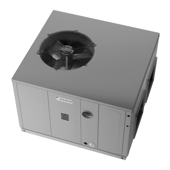
These installation instructions cover the outdoor installation
of self contained package air conditioners and heating units.
See the Specification Sheets applicable to your model for
information regarding accessories.
*NOTE: Please contact your distributor or our website for
the applicable Specification Sheets referred to in this manual.
This Forced Air Central Unit Design Complies With Require-
ments Embodied In The American National Standard / Na-
tional Standard of Canada Shown Below.
ANSI Z21.47•CSA-2.3 Central Furnaces.
www.daikincomfort.com
1
INSTALLATION INSTRUCTIONS
U
nit
Affix this manual and
Advertisement
Table of Contents

Related Manuals for Daikin DP14G M Series


Summary of Contents for Daikin DP14G M Series
-
Page 1: Table Of Contents
INSTALLATION INSTRUCTIONS DP14G M SERIES R-410A & c ingle AckAge lectRic eAting ooling Affix this manual and Users Information Manual adjacent to the unit. Index REPLACEMENT PARTS ..............3 ORDERING PARTS ..............3 SAFETY INSTRUCTIONS..............3 TO THE INSTALLER..............3 GENERAL INFORMATION .............. - Page 2 (QUALIFIED SERVICER ONLY) ........... 20 FILTERS ................. 12 MAIN BURNER FLAME (QUALIFIED SERVICER ONLY)..21 VENTING ..................12 CLEANING BURNERS ............21 FLUE HOOD INSTALLATION ..........12 ACCESSORIES AND FUNCTIONAL PARTS ........21 CONDENSATE DRAIN ..............12 SHEET METAL ACCESSORIES ..........21 CONDENSATE DRAIN CONNECTION ........12 FUNCTIONAL PARTS .............
-
Page 3: Replacement Parts
For the location of your nearest distributor, consult the white business pages, the yellow page section of the local telephone book or contact: HOMEOWNER SUPPORT DAIKIN NORTH AMERICA LLC 19001 KERMIER ROAD WALLER, TEXAS 77484 WARNING... - Page 4 CARBON MONOXIDE POISONING HAZARD RISQUE D’INTOXICATION AU MONOXYDE DE CARBONE Failure To Follow The Steps Outlined Below For Each Appliance Si les étapes décrites ci-dessous ne sont pas suivies pour chacun Connected To The Venting System Being Placed Into Operation des appareils raccordés au système de ventilation au moment Could Result In Carbon Monoxide Poisoning Or Death.
-
Page 5: General Information
Specification sheets can be found 4. File the claim with the following supporting documents: at www.daikincomfort.com for Daikin brand products. Within the website, please select the residential or commercial products menu a. Original Bill of Lading, certified copy, or indemnity bond. -
Page 6: Unit Location
Ground Level Installations Only: Unit location When the unit is installed on the ground adjacent to the WARNING • building, a level concrete (or equal) base is recommended. Prepare a base that is 3” larger than the package unit O PREVENT POSSIBLE E QUIPMENT D AMAGE, P ROPERTY DAMAGE, PERSONAL footprint and a minimum of 3”... -
Page 7: Roof Curb Installations Only
RIGGING DETAILS Rooftop Installation The unit may be installed directly on wood floors or on Class • A, Class B, or Class C roof covering material. WARNING To avoid possible personal injury, a safe, flat surface for • O PREVENT PROPERTY D AMAGE, T HE U NIT SHOULD R EMAIN IN A N UPRIGHT service personnel should be provided. -
Page 8: High Altitude Derate (U.s. Installations Only)
4. Install a drip leg to trap dirt and moisture before it can enter Inlet Gas Pressure the gas valve. The drip leg must be a minimum of three Natural Min. 5.0" W.C., Max. 10.0" W.C. inches long. Min. 11.0" W.C., Max. 13.0" W.C. Propane 5. -
Page 9: Gas Piping Checks
Gas Piping Checks Tanks and Piping Complete information regarding tank sizing for vaporization, recommended regulator settings and pipe sizing is available CAUTION from most regulator manufacturers and propane gas suppliers. O PREVENT PROPERTY DAMAGE OR P ERSONAL INJURY D UE T O FIRE, THE Since propane gas will quickly dissolve white lead or most FOLLOWING I NSTRUCTIONS M UST BE P ERFORMED R EGARDING G AS standard com mercial compounds, special pipe dope must... -
Page 10: Electrical Wiring
Thermostat Wiring - Two Stage Models WARNING O PREVENT PROPERTY D AMAGE OR S ERIOUS P ERSONAL INJURY D UE T O Thermostat FIRE O R EXPLOSION CAUSED B Y A PROPANE GAS LEAK, I NSTALL A GAS Two-Stage Heating DETECTING WARNING DEVICE. -
Page 11: Unit Voltage
Single phase models are shipped without horizontal duct covers. A duct system should be installed in accordance with Standards If needed, these kits may be ordered through Daikin’s Service of the National Board of Fire Underwriters for the Installation of Parts department. -
Page 12: Filters
Filters CONDENSATE DRAIN Condensate Drain Connection CAUTION A 3/4” NPT drain connection is supplied for condensate piping. An O PREVENT PROPERTY D AMAGE DUE TO F IRE AND LOSS OF external trap must be installed for proper condensate drainage. EQUIPMENT EFFICIENCY O R EQUIPMENT DAMAGE DUE TO DUST AND LINT NOTE: Maximum torque is 10 in-lbs. -
Page 13: Cooling
off electrical power and recheck for wiring errors, or obstructions in or near the blower motors. Duct covers must be removed Two-Stage Models: There is an adjustable HEAT FAN OFF delay of approximately before operating unit. 90/120/150/180 seconds (factory set at 150). If the unit is Rollout Protection Control operating at high stage when the call for heat is removed, the The rollout protection device opens, cutting power to the gas... -
Page 14: Gas Supply Pressure Measurement
Gas Supply Pressure Measurement 3. Set the room thermostat to its lowest possible setting. 4. Remove the heat exchanger door on the side of the unit by removing screws. CAUTION 5. This unit is equipped with an ignition device which automatically lights the main burner. -
Page 15: Gas Manifold Pressure Measurement And Adjustment
3. Inlet pressure tap connections: 1. Turn OFF gas to furnace at the manual gas shutoff valve external to the furnace. White-Rodgers 36G22 or 36G54 valve: 2. Turn OFF all electrical power to the system. Back inlet pressure test screw (inlet pressure boss) out one turn (counterclockwise, not more than one turn). -
Page 16: Temperature Rise Check
14. Close thermostat contacts to provide a call for heat. NOTE: Blower speed MUST be set to give the correct air temperature rise through the unit as marked on the rating plate. 15. Retest for leaks. If bubbles form, SHUT OFF GAS AND REPAIR ALL LEAKS IMMEDIATELY! External Static Pressure Check Input (Natural Gas Only) Check... -
Page 17: Cooling Startup
Cooling Startup Limit Check Check limit control operation after 15 minutes of operation by NOTE: Check all manual reset limit controls in heating circuit if blocking the return air grille(s). cooling mode does not operate. 1. After several minutes the main burners must go OFF. Compressor Protection Devices Blower will continue to run. -
Page 18: Checking Subcooling
c. Thermometer on Suction Line = 59°F. superheat or counterclockwise (out) to decrease superheat. Replace adjustment cap. Wait a minimum of 10 minutes To obtain the degrees temperature of superheat, subtract 50.0 from between adjustments to allow time for the TXV and pressures 59.0°F. - Page 19 and wiring. Disconnect electric power for five seconds. If LED Pressure Switch Stuck Closed remains off after restoring power, replace control. A stuck closed pressure switch can be caused by a faulty pressure switch or faulty wiring. If the control encounters a External Lockout pressure switch stuck closed, the induced draft blower remains An external lockout occurs if the integrated ignition control off.
-
Page 20: Abnormal Operation - Cooling
Abnormal Operation - Cooling should be replaced. Cabinet Finish Maintenance Short Cycle Compressor Delay The automatic ignition control has a built-in feature that prevents Use a fine grade automotive wax on the cabinet finish to maintain damage to the compressor in short cycling situations. In the the finish’s original high luster. -
Page 21: Main Burner Flame (Qualified Servicer Only)
speed reversible drill to the other end of the spring cable. Manifold Assembly Slowly rotate the cable with the drill and insert it into one of 3. Remove the burners. the primary heat exchanger tubes. While reversing the drill, 4. Use a bottle brush to clean burner insert and inside of the work the cable in and out several times to obtain sufficient burners. -
Page 22: Blower Performance Data
BLOWER PERFORMANCE DATA - SINGLE PHASE DP14GM2404041** - Rise Range: 25° - 55° T4 COOLING T5 COOLING T1 HEATING SPEED T2 HEATING SPEED T3 HEATING SPEED E.S.P. SPEED SPEED WATTS RISE WATTS RISE WATTS RISE WATTS WATTS 1,050 1,095 1,010 1,060 1,025 DP14GM2406041** - Rise Range: 30°... - Page 23 BLOWER PERFORMANCE DATA - SINGLE/THREE PHASE DP14GM3604041** - Rise Range: 25° - 55° T4 COOLING T5 COOLING T1 HEATING SPEED T2 HEATING SPEED T3 HEATING SPEED E.S.P. SPEED SPEED WATTS RISE WATTS RISE WATTS RISE WATTS WATTS 1,115 1,265 1,305 1,440 1,075 1,230...
- Page 24 BLOWER PERFORMANCE DATA - SINGLE/THREE PHASE DP14GM4806041** - Rise Range: 30° - 60° T4 COOLING T5 COOLING T1 HEATING SPEED T2 HEATING SPEED T3 HEATING SPEED E.S.P. SPEED SPEED WATTS RISE WATTS RISE WATTS RISE WATTS WATTS 1,055 1,380 1,415 1,570 1,780 1,000...
- Page 25 BLOWER PERFORMANCE DATA - SINGLE/THREE PHASE DP14GM6108041/43** - Rise Range: 30° - 60° T1 LOW STAGE HEATING T2 HIGH STAGE HEATING T3 LOW STAGE T4 HIGH STAGE T5 COOLING SPEED SPEED HEATING SPEED COOLING SPEED SPEED E.S.P. WATTS RISE WATTS RISE WATTS WATTS...
-
Page 26: Ignition Control Diagnostic Indicator Chart
IGNITION CONTROL DIAGNOSTIC INDICATOR CHART (SINGLE STAGE MODELS ONLY) Light Signal Refer to Abnormal Heating or Cooling Operation Sections of this Manual Internal Control Failure 1 Flash External Lockout 2 Flashes Pressure Switch Stuck Open 3 Flashes Pressure Switch Stuck Closed 4 Flashes Thermal Protection Device Open 5 Flashes... -
Page 27: Ignition Control Diagnostic Indicator Chart
IGNITION CONTROL DIAGNOSTIC INDICATOR CHART (TWO-STAGE MODELS ONLY) Red Light Signal Refer to Abnormal Heating or Cooling Operation Sections of this Manual Internal Control Failure 1 Flash External Lockout 2 Flashes Pressure Switch Stuck Open 3 Flashes Pressure Switch Stuck Closed 4 Flashes Thermal Protection Device Open 5 Flashes... -
Page 28: Appendix
APPENDIX UNIT DIMENSIONS Unit Dimensions (Inches) Chassis Model Height Size DP14GM24***41** 34 1/2 Medium DP14GM30***41** 34 1/2 Medium POWER WIRE ENTRANCE DP14GM36***41** 34 1/2 Medium 1.375 4.125 2.125 DP14GM42***41** 34 1/2 Medium DP14GM48***41** 42 1/2 Large DP14GM61***41** 43 1/2 Large RETURN 4.75 CONDENSATE DRAIN CONNECTION... -
Page 29: Minimum Clearances
MINIMUM CLEARANCES Clearance in accordance with local installation codes, the requirements of the gas supplier and the manufacturer’s installation instructions. Dégaugement conforme aux codes d’installation locaux, aux exigences du fournisseur de gaz et aux instructions d’installation du fabricant. NOTE: Roof overhang should be no more than 36”. RECOMMENDED FILTER SIZES UNIT 2 Ton... -
Page 30: Wiring Diagrams
WIRING DIAGRAMS... - Page 31 DP14GM(24, 30, 36, 42)41A* WIRING DIAGRAM HIGH VOLTAGE! DISCONNECT ALL POWER BEFORE SERVICING OR INSTALLING THIS UNIT. MULTIPLE POWER SOURCES MAY BE PRESENT. FAILURE TO DO SO MAY CAUSE PROPERTY DAMAGE, PERSONAL INJURY OR DEATH. Wiring is subject to change. Always refer to the wiring diagram on the unit for the most up-to-date wiring.
- Page 32 DP14G(24, 30, 36, 42)41A*WIRING DIAGRAM HIGH VOLTAGE! DISCONNECT ALL POWER BEFORE SERVICING OR INSTALLING THIS UNIT. MULTIPLE POWER SOURCES MAY BE PRESENT. FAILURE TO DO SO MAY CAUSE PROPERTY DAMAGE, PERSONAL INJURY OR DEATH. Wiring is subject to change. Always refer to the wiring diagram on the unit for the most up-to-date wiring.
- Page 33 DP14GM4841A* WIRING DIAGRAM HIGH VOLTAGE! DISCONNECT ALL POWER BEFORE SERVICING OR INSTALLING THIS UNIT. MULTIPLE POWER SOURCES MAY BE PRESENT. FAILURE TO DO SO MAY CAUSE PROPERTY DAMAGE, PERSONAL INJURY OR DEATH. Wiring is subject to change. Always refer to the wiring diagram on the unit for the most up-to-date wiring.
- Page 34 DP14GM4841A* WIRING DIAGRAM HIGH VOLTAGE! DISCONNECT ALL POWER BEFORE SERVICING OR INSTALLING THIS UNIT. MULTIPLE POWER SOURCES MAY BE PRESENT. FAILURE TO DO SO MAY CAUSE PROPERTY DAMAGE, PERSONAL INJURY OR DEATH. COMPONENT LEGEND SUPPLY VOLTAGE A UXILLARY LIMIT SWITCH 208-230/1/60 COMP COMPRESSOR...
- Page 35 DP14GM61***41** WIRING DIAGRAM HIGH VOLTAGE! DISCONNECT ALL POWER BEFORE SERVICING OR INSTALLING THIS UNIT. MULTIPLE POWER SOURCES MAY BE PRESENT. FAILURE TO DO SO MAY CAUSE PROPERTY DAMAGE, PERSONAL INJURY OR DEATH. Wiring is subject to change. Always refer to the wiring diagram on the unit for the most up-to-date wiring.
- Page 36 DP14GM61***41** WIRING DIAGRAM HIGH VOLTAGE! DISCONNECT ALL POWER BEFORE SERVICING OR INSTALLING THIS UNIT. MULTIPLE POWER SOURCES MAY BE PRESENT. FAILURE TO DO SO MAY CAUSE PROPERTY DAMAGE, PERSONAL INJURY OR DEATH. TRANSFORMER HIGH SUPPLY VOLTAGE HI LIMIT OUTPUT - 230 1/60 HI LIMIT INPUT PRESSURE SWITCH...
- Page 37 DP14GM36***43** WIRING DIAGRAM HIGH VOLTAGE! DISCONNECT ALL POWER BEFORE SERVICING OR INSTALLING THIS UNIT. MULTIPLE POWER SOURCES MAY BE PRESENT. FAILURE TO DO SO MAY CAUSE PROPERTY DAMAGE, PERSONAL INJURY OR DEATH. COMP CH OPTIONAL CONNECTED AT L1, L2 CH OPTIONAL NOTE 3 SEE NOTE 3 POWER SUPPLY...
- Page 38 DP14GM36***43** WIRING DIAGRAM HIGH VOLTAGE! DISCONNECT ALL POWER BEFORE SERVICING OR INSTALLING THIS UNIT. MULTIPLE POWER SOURCES MAY BE PRESENT. FAILURE TO DO SO MAY CAUSE PROPERTY DAMAGE, PERSONAL INJURY OR DEATH. COMPONENT LEGEND SUPPLY VOLTAGE AUXILLARY LIMIT SWITCH WIRING 208-230/3/60 CONTACTOR HIGH VOLTAGE...
- Page 39 DP14GM48***43** WIRING DIAGRAM HIGH VOLTAGE! DISCONNECT ALL POWER BEFORE SERVICING OR INSTALLING THIS UNIT. MULTIPLE POWER SOURCES MAY BE PRESENT. FAILURE TO DO SO MAY CAUSE PROPERTY DAMAGE, PERSONAL INJURY OR DEATH. COMP CH OPTIONAL CONNECTED AT L1, L2 CH OPTIONAL NOTE 3 SEE NOTE 3 POWER SUPPLY...
- Page 40 DP14GM48***43** WIRING DIAGRAM HIGH VOLTAGE! DISCONNECT ALL POWER BEFORE SERVICING OR INSTALLING THIS UNIT. MULTIPLE POWER SOURCES MAY BE PRESENT. FAILURE TO DO SO MAY CAUSE PROPERTY DAMAGE, PERSONAL INJURY OR DEATH. COMPONENT LEGEND SUPPLY VOLTAGE AUXILLARY LIMIT SWITCH 208-230/3/60 COMP COMPRESSOR NOTE 3...
- Page 41 DP14GM61***43** WIRING DIAGRAM HIGH VOLTAGE! DISCONNECT ALL POWER BEFORE SERVICING OR INSTALLING THIS UNIT. MULTIPLE POWER SOURCES MAY BE PRESENT. FAILURE TO DO SO MAY CAUSE PROPERTY DAMAGE, PERSONAL INJURY OR DEATH. SEE NOTE 3 COMP SEE NOTE 2 POWER SUPPLY BL BK 208-230/3/60 SEE NOTE 3...
- Page 42 DP14GM61***43** WIRING DIAGRAM HIGH VOLTAGE! DISCONNECT ALL POWER BEFORE SERVICING OR INSTALLING THIS UNIT. MULTIPLE POWER SOURCES MAY BE PRESENT. FAILURE TO DO SO MAY CAUSE PROPERTY DAMAGE, PERSONAL INJURY OR DEATH. PSW PRESS SWITCH SUPPLY VOLTAGE HLO HI LIMIT OUTPUT 208-230/3/60 HI LIMIT INPUT MVC MAIN GAS VALVE COMMON...
-
Page 43: Homeowner's Routine Maintenance
PACKAGE UNITS - DUAL FUEL & GAS HOMEOWNER’S ROUTINE MAINTENANCE RECOMMENDATIONS We strongly recommend a bi-annual maintenance checkup be performed by a qualified service agency before the heating and cooling seasons begin. Annual Inspection (Qualified Servicer Only) Your package unit should be inspected by a qualified installer, or service agency at least twice every year. -
Page 44: Start-Up Sheet
Residential Package - (Indoor Section) Model Number Serial Number ELECTRICAL Line Voltage (Measure L1 and L2 Voltage) L1 - L2 Secondary Voltage (Measure Transformer Output Voltage) R - C Blower Amps Heat Strip 1 - Amps Heat Strip 2 - Amps BLOWER EXTERNAL STATIC PRESSURE Return Air Static Pressure IN. - Page 45 THIS PAGE LEFT INTENTIONALLY BLANK...
- Page 46 THIS PAGE LEFT INTENTIONALLY BLANK...
- Page 47 THIS PAGE LEFT INTENTIONALLY BLANK...
- Page 48 CUSTOMER FEEDBACK Daikin is very interested in all product comments. Please fill out the feedback form on the following link: https://daikincomfort.com/contact-us You can also scan the QR code on the right to be directed to the feedback page. Our continuing commitment to quality products may mean a change in specifications without notice.
Need help?
Do you have a question about the DP14G M Series and is the answer not in the manual?
Questions and answers