
Related Manuals for Nice ARIA


Summary of Contents for Nice ARIA
- Page 1 Nice ARIA Operator for swing gates Instructions and warnings for installation...
-
Page 2: Table Of Contents
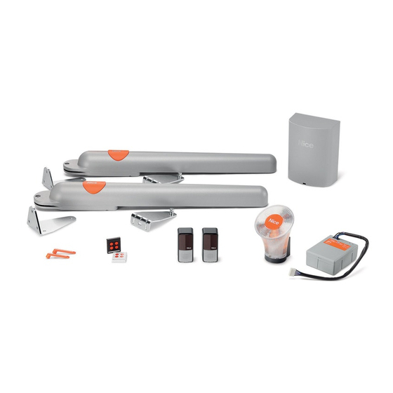
2. 3 PRODUCT TECHNICAL SPECIFICATIONS 2. 4 PRE-INSTALLATION WORKS 2. 5 INSTALLING THE ARIA GEARMOTORS (models 400C/600C) and CLB CONTROL UNIT (models 202/201) 2. 6 INSTALLING THE PHOTOCELLS model PH200 2. 7 INSTALLING THE FLASHING LIGHT model FL200 ELECTRICAL CONNECTIONS 3. - Page 3 ARIA200M ARIA400M ECCO5WO FL200 PH200 KIT ARIA200 ARIA200 M FL200 PH200 ECCO5WO KIT ARIA200START ARIA200 M KIT ARIA400 ARIA400 M FL200 PH200 ECCO5WO • • - The optional • • étape A = observer étape C = raccorder Step A = observe Step C = connect Step D = initial start-up of the system carried step A = osservare...
- Page 4 ARIA200M ARIA400M ECCO5WO FL200 PH200 KIT ARIA200 ARIA200 M FL200 PH200 ECCO5WO KIT ARIA200START ARIA200 M KIT ARIA400 ARIA400 M FL200 PH200 ECCO5WO • • - The optional • • étape A = observer étape C = raccorder Step A = observe Step C = connect Step D = initial start-up of the system carried step A = osservare...
- Page 5 Step FL200 CLB202 CLB201 PH200 PH200 PH200 PH200 ARIA200 ARIA400 ARIA200 ARIA400 • Voir le tableau • - See Table 1 2.4 • Step • FR - Tableau 0 • EN - Table 0 • IT - Tabella 0 • PL - Tabela 0 0 >...
- Page 6 740mm VIII...
- Page 7 180° 740mm 180° 180°...
- Page 8 PH200 Installation of FL200...
- Page 9 PH200 Ø < 5 mm Led SAFE...
- Page 10 FL200 05. A Ø = 6 mm Ø = 6 mm (flash) (aerial)
- Page 11 Step Stop Sbs Open • • - marrone • - jaune-vert • - yellow/ green • - giallo/verde • • • • led Sto p led Open led Sb S led ECSbus Flash Stop Open tous les autres composants requis pour l’installa tion (optional and not prima di chiudere il coperchio del motoriduttore...
- Page 12 Step Voir le chapitre To start-up the system, see Chapter Per procedere con la prima accensione dell'impianto, vedere il capitolo Step Voir le chapitre To PROGRAMME the system, see Chapter Per procedere con la PROGRAMMAZIONE dell'impianto, vedere il capitolo...
-
Page 13: Installation
residential use. sidered improper and is forbidden direct current outage. Step Step INSTALLATION Model type ARIA200M ARIA400M Product type Maximum inrush torque Nominal torque Nominal torque speed Maximum frequency of cycles 4 minutes 4 minutes Application limits Maximum power input IP44 Model type Product type... -
Page 14: Pre-Installation Works
OGI output ECSbus output Stop input Stop command) SbS input command) Open input Radio aerial input Assembly Vertical, wall-mounted IP44 Possibility of remote control Memory capacity Auto-detection 2. 4 - PRE-INSTALLATION WORKS a standard and customary layout. nection. cascade star combined electrical conductors . - Page 15 H07RN-F for outdoor environments. must be disconnected 2. 1. 2. 5.1 - INSTALLING THE ARIA GEARMOTORS 200M/400M Table 0 ( (Phase 04 - porting surface is solid. Phase 05 - 10. Manually perform a few gate leaf opening and closing manoeuvres 2.
-
Page 16: Electrical Connections
Step ELECTRICAL CONNECTIONS • of the system to the mains power or replacement of the cable supplied Step Flash ECSbus Stop Open PROGRAMMING P1 = radio transmitter memorisation P2 = slow/fast movement speed selection (Par. 4. selection (Par. P4 = automation motion command 02. -
Page 17: Memorisation Of Gate Leaf Opening And Closing Angles
2 3 4 5 2 3 4 5 2 3 4 5 2 3 4 5 2 3 4 5 ARIA 200 2 3 4 5 2 3 4 5 2 3 4 5 2 3 4 5 2 3 4 5... -
Page 18: St Transmitter
is not M1 , press and release blue brown TRANSMITTER and observe the indicated times. allows for simultaneously memorising all the transmitter keys Keys Paired command Pedestrian opening Memorisation procedure 01. On the control unit led L1 slow fast led L2 o slow led L2 on fast... -
Page 19: Testing And Commissioning
Flash Stop Open Flash Stop Open ciclo completo TESTING AND COMMISSIONING 5. 1 - TESTING 5. 2 - COMMISSIONING strictly prohibited. 12). MAINTENANCE standards. - Page 20 version. 8. 1 - ADVANCED SETTINGS complete cycle • • Step by Step function • • 8. 1.1.1 - 01. On the transmitter ) simultaneously press and buttons T1 and T2 Table 4 parameter. Parameters Value Actions to be per - used formed Pause time...
-
Page 21: Presence Function
Parameters Value Actions to be per - used formed Pedestrian Motor force Medium-low * Step-by-Step Open - Stop - Close - Open * * Factory value 8. 1.1.2 - 01. On the transmitter ) simultaneously press and Table 5 parameter. Parameters Value Actions to be per -... -
Page 22: Adding Or Removing Devices
01. On the transmitter ) simultaneously press and buttons T1 and T2 Parameters Actions to be performed Pause time Motor force Step by Step function 01. On the transmitter ) simultaneously press and Table 7 Parameters Actions to be performed 8. -
Page 23: Memorising Additional Transmitters
Photocell Photocell gate’s movement) disengages) gate’s movement) gate’s movement) disengages) MEMORISING ADDITIONAL TRANSMITTERS (Par. 4. Mode 1 memorisation procedure allows for simultaneously memorising all the transmitter Table 9 . Keys Paired command Pedestrian opening Memorisation procedure 01. On the control unit led L1 Mode 2 memorisation procedure allows for memorising... - Page 24 wait 1 second between two successive steps 02. On the NEW transmitter 8 seconds On the OLD transmitter 2 seconds 04. On the OLD transmitter 2 seconds 05. On the OLD transmitter 2 seconds On the NEW transmitter 5 seconds wait 1 second between two successive steps 02.
-
Page 25: Diagnostics And Device Signals
PR100 SOLEKIT 8. 8 - DIAGNOSTICS AND DEVICE SIGNALS SAFE Table Status Action faulty second pause unit Normal operation Normal operation tocell lenses Always lit Table 12 . Status Action 1 second pause 1 second pause 1 second pause vated 1 second pause 1-second pause control unit... -
Page 26: Specifications
Status Action Motor selector con guration not 1-second pause allowed ECSbus led Status Action Fault Serious fault Input status variation seconds the red LED transmitter) Stop led Status Action Stop input active SbS led Status Action OPEN LED Status Action Led L1 Status Action... - Page 27 8. 9.2 - Stop input ments, multiple devices – even of di erent type – (read Table 14 Note 1 Note 2 In parallel (Note 2 ) (Note 1 ) In parallel tity limit. (Note 1 ) In series ( In series Note 4 In parallel...
- Page 28 Symptoms Probable cause and possible solution The radio transmitter does not emit any The manoeuvre fails to start and the ECSbus led on the control unit does power outlet. The manoeuvre fails to start and the The manoeuvre fails to start and the Table 11 .
- Page 29 WARNINGS fully open and stopped. • Keep the transmitters away from children. Manually 180° 180° Maintenance operations immediately replaced.
- Page 30 –––––––––––––––––––– ................
- Page 31 ARIA200M ARIA400M ECCO5WO FL200 PH200 KIT ARIA200 ARIA200 M FL200 PH200 ECCO5WO KIT ARIA200START ARIA200 M KIT ARIA400 ARIA400 M FL200 PH200 ECCO5WO • • - The optional • • étape A = observer étape C = raccorder Step A = observe Step C = connect Step D = initial start-up of the system carried step A = osservare...
Need help?
Do you have a question about the ARIA and is the answer not in the manual?
Questions and answers