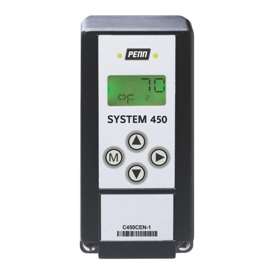
Penn 450 Series Installation Manual
Condensing unit control module
Hide thumbs
Also See for 450 Series:
- Technical bulletin (146 pages) ,
- Installation manual (41 pages) ,
- Installation instructions manual (29 pages)
Table of Contents
Advertisement
Quick Links
Description
The System 450™ Series condensing unit control module
controls space temperature, scheduled defrost cycles,
evaporator fans, and optional pump down compressor
control on medium and low temperature refrigeration
condensing units.
You can use the C450CCU-4 control module, in conjunction
with optional System 450 relay output expansion modules,
to build a variety of custom condensing unit control
systems for small and medium capacity refrigeration
applications.
The C450CCU-4 condensing unit control system provides
passive, off-cycle defrost control or active, electric heat
defrost control. Depending on the application, you can
terminate defrost cycles based on time or based on
sensed evaporator temperature. You can use a menu
option to manually initiate or terminate a defrost cycle at
any time.
You can also control single-speed or two-speed evaporator
fans, and add an optional pressure transducer for pump
down pressure control of the compressor.
Refer to the System 450 Series C450CCU Condensing
Unit Control System Technical Bulletin (LIT-12013266) for
detailed information about how to set up, operate, and
troubleshoot a System 450 condensing unit control
system.
Application
Important: Use the System 450 Series C450CCU
condensing unit control module only as an
operating control. Where failure or malfunction
of the condensing unit control module could lead
to personal injury or property damage to the
controlled equipment or other property, additional
precautions must be designed into the control
system. Incorporate and maintain other devices,
such as supervisory or alarm systems or safety or
limit controls, intended to warn of or protect against
failure or malfunction of the condensing unit control
module.
Important: Utiliser ce System 450 Series C450CCU
condensing unit control module uniquement en
tant que dispositif de contrôle de fonctionnement.
Lorsqu'une défaillance ou un dysfonctionnement
du régulateur risque de provoquer des blessures
ou d'endommager l'équipement contrôlé ou un
autre équipement, la conception du système de
contrôle doit intégrer des dispositifs de protection
supplémentaires. Veiller dans ce cas à intégrer de
façon permanente d'autres dispositifs, tels que
des systèmes de supervision ou d'alarme, ou des
dispositifs de sécurité ou de limitation, ayant une
fonction d'avertissement ou de protection en cas de
défaillance ou de dysfonctionnement du régulateur.
System 450 Series C450CCU Condensing Unit
Control Module Installation Guide
Installation
Figure 1: System 450 module dimensions, mm (in.)
Table 1: System 450 module dimensions, mm (in.)
Callout
Description
1
35 mm DIN rail mount channel
2
12.7 mm (1/2 in.) conduit hole, nominal trade size
Mounting modules and module
assemblies
Observe the following location and mounting guidelines.
• Make sure that the mounting surface can support the
module assembly, DIN rail, mounting hardware, and
any user-supplied panel or enclosure.
• Mount the modules upright and plugged together in a
horizontal row where possible, as shown in Figure 2. It
is best practice to mount the control module on a DIN
rail.
• In direct-mount applications, mount the modules on flat
and even surfaces.
• Allow sufficient space to make connections, run wires,
and view the LCD and LEDs.
• Mount the modules in locations free of corrosive
vapors, and observe the ambient operating conditions
listed in the
C450CCU condensing unit control module
technical
specifications.
• Do not mount the modules on surfaces that are prone
to vibration or in locations where high-voltage relays
and motor-starters, electromagnetic emissions, or
strong radio frequency may cause interference.
24-7664-03809 Part No. Rev. C
2020-10-21
C450CCU
Advertisement
Table of Contents

Summary of Contents for Penn 450 Series
- Page 1 You can also control single-speed or two-speed evaporator fans, and add an optional pressure transducer for pump down pressure control of the compressor. Refer to the System 450 Series C450CCU Condensing Unit Control System Technical Bulletin (LIT-12013266) for detailed information about how to set up, operate, and Table 1: System 450 module dimensions, mm (in.)
- Page 2 450 modules. Use proper ESD precautions when module assembly evenly on the surface. you install and service the modules to avoid damage to System 450 modules. System 450 Series C450CCU Condensing Unit Control Module Installation Guide...
- Page 3 Provides low-voltage common Figure 2: C450CCU condensing unit control system connections for passive or active sensors that you connect to the 5 V, Sn1, and Sn2 terminals. The terminals connect internally. System 450 Series C450CCU Condensing Unit Control Module Installation Guide...
- Page 4 0 psis to 200 psis, sealed for wet and freeze and thaw WHA-C450-100C System 450 module connection extension cable, 100 cm (3.3 ft) long applications; order a WHA-PKD3 type wire harness separately. System 450 Series C450CCU Condensing Unit Control Module Installation Guide...
- Page 5 Use of the software that is in (or constitutes) this product, or access to the cloud, or hosted services applicable to this product, if any, is subject to applicable end-user license, open-source System 450 Series C450CCU Condensing Unit Control Module Installation Guide...
- Page 6 software information, and other terms set forth at www.johnsoncontrols.com/techterms. Your use of this product constitutes an agreement to such terms. Single point of contact APAC Europe NA/SA JOHNSON CONTROLS JOHNSON CONTROLS JOHNSON CONTROLS C/O CONTROLS PRODUCT WESTENDHOF 3 507 E MICHIGAN ST MANAGEMENT 45143 ESSEN MILWAUKEE WI 53202...


Need help?
Do you have a question about the 450 Series and is the answer not in the manual?
Questions and answers