Table of Contents
Advertisement
Quick Links
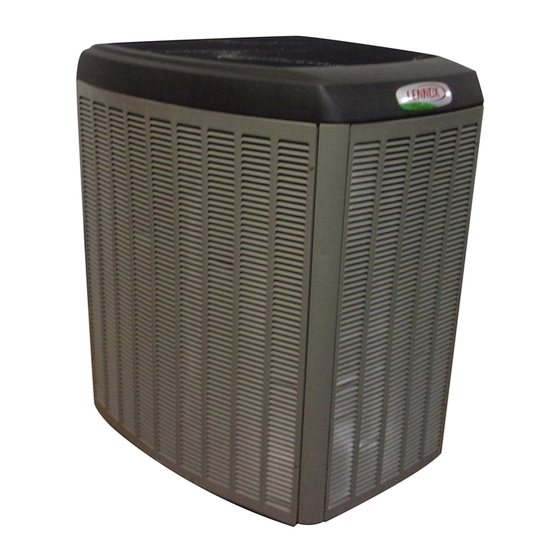
E2010 Lennox Industries Inc.
Dallas, Texas, USA
A thermostat is not included and must be ordered
separately.
The Lennox ComfortSense
used, as well as other thermostats.
In all cases, setup is critical to ensure proper system
operation.
Field wiring is illustrated in diagrams, which begin on
Page 19.
Improper installation, adjustment, alteration, service or
maintenance can cause personal injury, loss of life, or
damage to property.
Installation and service must be performed by a licensed
professional installer (or equivalent) or a service agency.
General
This single−stage outdoor unit is designed for use with
HFC−410A refrigerant only. This unit must be installed
with an approved indoor air handler or coil. See the
Lennox XC17 Engineering Handbook for approved
indoor component matchups.
This model is designed for use in expansion valve
systems only. An indoor expansion valve approved for
use with HFC−410A refrigerant must be ordered
separately, and installed prior to operating the system.
04/10
*2P0410*
Downloaded from
ManualsNet.com
NOTICE
®
7000 thermostat may be
WARNING
IMPORTANT
search engine
INSTALLATION
INSTRUCTIONS
Dave Lennox Signature
Collection XC17 Units
AIR CONDITIONER
506510−01
04/10
Supersedes 506498−01
RETAIN THESE INSTRUCTIONS FOR FUTURE
TABLE OF CONTENTS
. . . . . . . . . . . . . . . . . . . . . . . . . . . . . . . . . . . . . .
. . . . . . . . . . . . . . . . . . . . . . . . . . . . . . .
. . . . . . . . . . . . . . . . . . . . . . . . . . . . . . . . . . . . .
. . . . . . . . . . . . . . . . . . . . . . . . . . . . . . . . . .
Shipping and Packing List
Check unit for shipping damage. Consult last carrier
immediately if damage is found.
1
Assembled outdoor unit.
1
Bag assembly which includes the following:
1
Bushing (for low voltage wiring)
2
Isolation grommets for liquid and suction lines
Page 1
®
Litho U.S.A.
REFERENCE
. . . . . . . . . . . . . . . . . . . . . .
. . . . . . . . . . . . . . . . . . . .
. . . . . . . . . . . . . . . . . . . . . . . .
. . . . . . . . .
. . . . . . . . . . . . . . . . . . .
. . . . . . . . . . . . . . . . .
. . . . . . . . . . . . . . . . . . .
. . . . . . . . . . . . . . . . . . . . . . . . . . .
. . . . . . . . . . . . . . . . . . . . . . .
. . . . . . . . . . . . . . . . . . . . . . . . .
. . . . . . . . . . . . .
. . . . . . . . . . . . . . . . . . . . . . . . . . . .
. . . . . . . . . .
. . . . . . . . . . . . . . . . . . . . . . . . . . . .
. . . . . . . . . . .
. . . . . . . . . . . . . . . . . . . . . . . . . . . .
. . . . . . . . . . . . . . . . . .
. . . . . . . . . . .
. . . . . . . . . . . . .
506510−01
*P506510-01*
1
1
2
2
3
4
. . . . .
6
7
10
11
14
16
16
19
22
24
26
26
26
30
31
35
42
48
Advertisement
Table of Contents

Subscribe to Our Youtube Channel
Related Manuals for Lennox Signature XC17


Summary of Contents for Lennox Signature XC17
-
Page 1: Table Of Contents
Start−Up and Performance Checklist ... . . with an approved indoor air handler or coil. See the Lennox XC17 Engineering Handbook for approved Shipping and Packing List indoor component matchups. -
Page 2: Unit Dimensions
Unit Dimensions − Inches (mm) and Parts Arrangement DISCHARGE AIR 39.40" 35.50" (1003) ELECTRICAL INLETS (902) [−024] 41 (1040) [−030 THROUGH −060] 47 (1194) SUCTION LINE INLET LIQUID LINE 18.60" INLET (470) 8.00" (203) 1 (25) ACCESS VIEW SIDE VIEW UNIT SUPPORT FEET 16−7/8... -
Page 3: Unit Parts Arrangement
Typical Unit Parts Arrangement FAN MOTOR CONTROL PULSE−WIDTH MODULATION (PWM) GROUND LUG CONTACTOR−1POLE (K1−1) WIRE TIE HIGH VOLTAGE FIELD CONNECTIONS SLEEVE OUTDOOR AMBIENT TEMPERATURE SENSOR CAPACITOR (C12) MAIN CONTROL CONTROL BOX FAN MOTOR SURGE PROTECTION HIGH DISCHARGE LINE TEMPERATURE SENSOR COMPRESSOR HARNESS MUFFLER... -
Page 4: Operating Gauge Set And Service Valves
The Clean Air Act of 1990 bans the intentional venting of See the Lennox Service and Application Notes #C−08−1 refrigerant (CFCs, HCFCs AND HFCs) as of July 1, for further details and information. - Page 5 SERVICE VALVES SERVICE PORT CAP SERVICE PORT VARIOUS TYPES SERVICE PORT CORE (VALVE STEM SHOWN OPEN TO BOTH INDOOR AND CLOSED) INSERT HEX OUTDOOR UNITS WRENCH HERE SERVICE PORT CAP VALVE STEM FRONT-SEATED SERVICE PORT SERVICE PORT CORE TO INDOOR (VALVE STEM UNIT SHOWN OPEN)
-
Page 6: Recovering Refrigerant From Existing System
Recovering Refrigerant from Existing System RECOVERING REFRIGERANT FROM SYSTEM DISCONNECT POWER CONNECT MANIFOLD GAUGE SET Disconnect all power to the existing outdoor unit at the disconnect Connect a gauge set, clean recovery cylinder and a recovery switch or main fuse box/breaker panel. machine to the service ports of the existing unit. -
Page 7: New Outdoor Unit Placement
MINIMUM CLEARANCE CLEARANCE ON ALL SIDES INCHES (MILLIMETERS) ABOVE UNIT 6 (152) ACCESS PANEL NOTES: CONTROL PANEL 48 (1219) Clearance to one of the other three ACCESS LOCATION sides must be 36 inches (914mm). 30 (762) 12 (305) Clearance to one of the remaining two sides may be 12 inches (305mm) and the final side may be 6 inches (152mm). - Page 8 ELEVATING THE UNIT With unit positioned at installation site perform the following Units are outfitted with elongated support feet as illustrated in Figure 4, Detail C. 1. Remove two side louvered panels to expose the unit base. If additional elevation is necessary, raise the unit by 2.
- Page 9 DETAIL A DETAIL B INSTALL UNIT LEVEL OR, IF ON A SLOPE, MAINTAIN SLOPE TOLERANCE OF 2 DEGREES (OR 2 INCHES PER 5 FEET [50 MM PER 1.5 M]) AWAY INSTALL UNIT AWAY FROM WINDOWS FROM BUILDING STRUCTURE. BUILDING STRUCTURE MOUNTING TWO 90°...
-
Page 10: Removing And Installing Panels
Removing and Installing Panels ACCESS PANEL REMOVAL PANELS Removal and reinstallation of the access panel is as illustrated. ACCESS AND LOUVERED REMOVE 4 SCREWS TO REMOVE PANEL FOR WARNING ACCESSING COMPRESSOR AND CONTROLS. To prevent personal injury, or damage to panels, unit or structure, be sure to observe POSITION PANEL WITH HOLES the following: ALIGNED;... -
Page 11: New Or Replacement Line Set
ARCTIC 22 CC or ICI EMKARATEt RL32CF. isolate the opening so vibration is not transmitted to the To obtain the correct information from Lennox, be sure to building. Pay close attention to line set isolation during communicate the following information: installation of any HVAC system. - Page 12 LINE SET IMPORTANT Refrigerant lines must not contact structure. INSTALLATION REFRIGERANT LINE SET INSTALLING Line Set Isolation The following illustrations are VERTICAL RUNS (NEW CONSTRUCTION SHOWN) examples of proper refrigerant line set isolation: NOTE Insulate liquid line when it is routed through areas where the surrounding ambient temperature could become higher than the REFRIGERANT LINE SET TRANSITION...
- Page 13 BRAZING NOTE − Use silver alloy brazing rods with five or six percent minimum silver alloy for copper−to−copper brazing, 45 percent alloy for copper−to−brass and copper−to−steel brazing. CONNECTIONS CAP AND CORE REMOVAL Remove service cap and core CUT AND DEBUR from both the vapor and liquid line service ports.
-
Page 14: Flushing The System
Flushing the System TYPICAL CHECK EXPANSION VALVE FLUSHING REMOVAL PROCEDURE (Uncased Coil Shown) STUB END LINE SET AND INDOOR COIL (1 OF 2) TWO PIECE PATCH PLATE LIQUID LINE CHECK (UNCASED COIL ONLY) ORIFICE EXPANSION TYPICAL FIXED ORIFICE REMOVAL PROCEDURE HOUSING VALVE DISTRIBUTOR... - Page 15 FLUSHING LINE SET AND INDOOR COIL (2 OF 2) TYPICAL CHECK EXPANSION VALVE INSTALLATION PROCEDURE This outdoor unit is designed for use in systems that use check expansion valve metering device. See the Lennox XC17 Engineering Handbook for approved check expansion valve kit match−ups and application information.
-
Page 16: Leak Testing The System
Polyol ester (POE) oils death. are used in Lennox units charged with HFC−410A refrigerant. Residual mineral oil can act as an Never use oxygen to pressurize or purge refrigeration lines. Oxygen, insulator, preventing proper heat transfer. - Page 17 LEAK TEST LINE SET AND INDOOR COIL NOTE Normally, the high pressure hose is connected to the liquid line port. How- ever, connecting it to the vapor port better protects the manifold gauge set from high pressure damage. CONNECT GAUGE SET Connect an HFC−410A manifold gauge set high pressure hose to the vapor valve service port.
-
Page 18: Evacuating The System
Evacuating the System EVACUATING MANIFOLD GAUGE SET LINE SET AND INDOOR COIL CONNECT GAUGE SET HIGH NOTE Remove cores from service valves (if not al- ready done). Connect low side of manifold gauge set with 1/4 SAE in−line tee to vapor line OUTDOOR service valve UNIT... -
Page 19: Electrical
temperatures and pressures present during operation of IMPORTANT an air conditioning system. Non−condensables and water suction combine with refrigerant to produce substances Use a thermocouple or thermistor electronic vacuum that corrode copper piping and compressor parts. gauge that is calibrated in microns. Use an instrument Electrical capable of accurately measuring down to 50 microns. - Page 20 ROUTE CONTROL WIRES Install low voltage control wiring from outdoor to indoor unit and from CONTROL PANEL thermostat to indoor unit as illustrated. See Figures 10 and 10 for typical configurations. Run 24VAC control wires through hole with grommet. Make 24VAC control wire connections to Main Control. NOTE Do not bundle any excess 24VAC control wires inside control panel.
- Page 21 Figure 7. Typical XC17 Wiring Page 21 XC17 SERIES Downloaded from ManualsNet.com search engine...
-
Page 22: Main Control Jumpers And Terminals
Main Control Jumpers and Terminals MAIN CONTROL AIR CONDITIONER ONE STAGE TABLE 3 PROVIDES ADDITIONAL INFORMATION CONCERNING JUMPERS, LOOP, AND CONNECTIONS FOR THE MAIN CONTROL. TEST PINS DS11 and DS14 LED ALERT CODES DS13 and DS15 LED ALERT CODES CUT FOR HUMIDITROL ENHANCED DEHUMIDIFICATION ACCESSORY (EDA) APPLICATIONS. - Page 23 Table 3. Main Control Jumpers and Terminals Board ID Label Description PSC Fan 240 VAC output connection for outdoor fan. PSC Fan 240 VAC input connection for outdoor fan. 24VAC output for defrost auxiliary heat output. Thermostat service light connection. 24VAC thermostat input/output for second stage operation of the unit.
-
Page 24: Field Control Wiring
Field Control Wiring ComfortSense[ 7000 Thermostats One−Stage Air Handler Control Catalog # Y0349 or Y2081 Air Conditioner Control On−board link Low voltage thermostat wiring Flat metal jumper Outdoor sensor for outdoor temperature display (Optional). R connection required for outdoor unit with Control LSOM function. Resistor Kit (Cat# 47W97) is required when using the ComfortSense 7000 (Y0349) with Control LSOM feature. - Page 25 ComfortSense[ 7000 Thermostats One−Stage Furnace Control Catalog # Y0349 or Y2081 Air Conditioner Control On−board link Low voltage thermostat wiring Cut on−board link (W914) (clippable wire) from DS to R for dehumidification (Optional). Outdoor sensor for outdoor temperature display (Optional). R connection required for outdoor unit with Control LSOM function.
-
Page 26: Servicing Unit Delivered Void Of Charge
1. Rotate fan to check for binding. Servicing Units Delivered Void of Charge 2. Inspect all factory− and field−installed wiring for loose If the outdoor unit is void of refrigerant, clean the system connections. using the procedure described below. 3. After evacuation is complete, open both the liquid and 1. - Page 27 ADDING OR REMOVING REFRIGERANT This system uses HFC−410A refrigerant which operates at much higher pressures than HCFC−22. The pre−installed liquid line filter drier is approved for use with HFC−410A only. Do not replace it with components designed for use with HCFC−22. This unit is NOT approved for use with coils which use capillary tubes or fixed orifices as a refrigerant metering device.
- Page 28 WEIGH IN to initially charge a system when the outdoor unit is void of charge. To verify charge and add or APPROACH SUBCOOLING remove refrigerant use either methods. WHEN TO CHARGE? START: Determine the correct charge method: Warm weather best Can charge in colder weather CHARGE METHOD? Determine by: Outdoor ambient temperature...
- Page 29 APPROACH 1. Confirm proper airflow across coil using Figure 12. 2. Compare unit pressures with Table 4, Normal Operating Pressures. TEST AND CHARGE METHOD 3. Use APPROACH to correctly charge unit or to verify the charge is 65ºF (18.3ºC) and Above correct.
-
Page 30: Operating And Temperature Pressures
Operating and Temperature Pressures Minor variations in these pressures may be expected due to differences in installations. Significant differences could mean that the system is not properly charged or that a problem exists with some component in the system. Table 4. Normal Operating Pressures (Liquid +10 and Suction +5 psig)* Use this table to perform maintenance checks;... -
Page 31: System Operations
OUTDOOR AMBIENT TEMPERATURE (RT13) System Operation If the outdoor ambient temperature sensor detected a IMPORTANT open, or out of range −40ºF to +140ºF (−40ºC to 60ºC) then LED alert codes are displayed, however cooling operation will continue. See Table 9 for LED alert codes for the Some scroll compressor have internal vacuum protector ambient sensor. - Page 32 TEST PINS FUNCTION Placing the JUMPER ON the field test pins (E33) (see Page 22 for location of TEST pins) allows the technician to Clear compressor anti−short cycle delay. Clear five−strike fault lockouts High / Low pressure switches and High Discharge Temperature Sensor. Y1 Active Place a JUMPER ON the TEST pins for longer than one...
- Page 33 Table 6. Ambient Sensor Temperature / Resistance Range Degrees Degrees Degrees Degrees Resistance Resistance Resistance Resistance Fahrenheit Fahrenheit Fahrenheit Fahrenheit 136.3 2680 56.8 16657 21.6 44154 −11.3 123152 133.1 2859 56.0 16973 21.0 44851 −11.9 125787 130.1 3040 55.3 17293 20.5 45560 −12.6...
- Page 34 Table 7. High Discharge Sensor Temperature / Resistance Range Degrees Degrees Degrees Degrees Resistance Resistance Resistance Resistance Fahrenheit Fahrenheit Fahrenheit Fahrenheit 303.1 186.1 1052 136.8 2656 94.5 6613 298.1 185.0 1072 136.0 2698 93.6 6739 293.4 183.9 1093 135.2 2740 92.8 6869 289.0...
-
Page 35: Main Control Led Alert Codes
Table 8. Sensor Temperature / Resistance Range These LEDs display the most common fault conditions in the system. When an abnormal condition is detected, this Temperature Resistance values Pins/Wire Range °F (°C) range (ohms) Color function communicates the specific condition through Sensor LEDs. - Page 36 Outdoor Main Control LEDs Condition Condition Condition Possible Cause(s) Possible Cause(s) Possible Cause(s) Solution Solution Solution DS11 DS11 DS14 Red DS14 Red Green Green 1 Fast Heating Low Flash then Capacity Pause 2 Fast Heating High Flash then Capacity Pause 2 Fast Flash then Defrost...
- Page 37 Table 10. Compressor LED Alert Codes Outdoor Main Control LEDs Possible Condition Solution Clearing Status Cause(s) DS15 DS13 Yellow Compressor protector is open. Check for high head pressure Check compressor supply voltage Thermostat Clears the error after current Outdoor unit power disconnect is open. Compressor demand signal Y1 is sensed in the run and...
- Page 38 Outdoor Main Control LEDs Possible Possible Condition Condition Solution Solution Clearing Status Clearing Status Cause(s) Cause(s) DS15 DS13 Yellow Outdoor unit power disconnect is open. Unit circuit breaker or fuse(s) is open. Unit contactor has failed to close. Check compressor contactor wiring and con- nectors Check for compressor contactor failure (burned, pitted or open)
- Page 39 Figure 19. High Pressure Switch Operation Page 39 XC17 SERIES Downloaded from ManualsNet.com search engine...
- Page 40 Figure 20. Low Pressure Switch Operation Page 40 506510−01 Downloaded from ManualsNet.com search engine...
- Page 41 Figure 21. High Discharge Temperature Sensor Operation Page 41 XC17 SERIES Downloaded from ManualsNet.com search engine...
-
Page 42: Maintenance (Dealer And Homeowner)
Maintenance VERIFYING LED STATUS CODES WARNING During start up, the fan motor control LED will Electric shock hazard. Can cause injury display any error conditions. If error conditions or death. Before attempting to perform exist then no other codes will display. If no error any service or maintenance, turn the conditions are present, then the stage status and electrical power to unit OFF at disconnect... - Page 43 LED CODES AND SEQUENCE OF OPERATIONS During start up, the LED will first display any error conditions (see table 12) if present. If no errors are detected then the LED code indicating one or two stage operation will display then a long pause. The RPM indicator is displayed next. After the RPM indicator is displayed there is a short pause and the sequence repeats if a thermostat demand is still present.
- Page 44 CFM Profile Pin Select FAN MOTOR CONTROL PULSE−WIDTH MODULATION (PWM) JUMPER JUMPER CONTROL PANEL MAIN CONTROL VERIFY DC VOLTAGE OUTPUT USING FAN PWM OUT AND COM TERMINALS. SEE TABLE 11 FOR OPTIMAL DC VOLTAGE BASED ON CFM PROFILE USED. FAN PWM OUT GREEN GREEN YELLOW...
- Page 45 FAN MOTOR CONTROL PULSE−WIDTH MODULATION (PWM) CONTROL PANEL MAIN CONTROL BLACK WIRE TO MAIN CONTROL EXT PWR/R YELLOW WIRE GREEN GREEN YELLOW YELLOW BLACK BROWN BLACK BLUE YELLOW BLACK YELLOW PWM FAN YELLOW BLACK CONTROL SEE TABLE 11 FOR CFM PROFILE SELECTION OPTIONS. Figure 24.
- Page 46 FAN MOTOR TEST PROCEDURE A simple test can be used to test the fan motor operation. A fully charged 9V battery will be required for this procedure. FAN MOTOR TEST This is a test that will verify that the motor does operate. 1.
- Page 47 Indoor Unit the line fuse blows or circuit breaker trips but there is no 1. Clean or change filters. visible damage to the MOV(s), the simplest test may be to 2. Lennox blower motors prelubricated just temporarily remove the MOV(s) and see if the problem permanently sealed.
-
Page 48: Start−Up And Performance Checklist
Accessories 1. Air Filter Ask your Lennox dealer to show you For update−to−date information, see any of the following where your indoor unit’s filter is located. It will be either... - Page 49 XC17 Start−Up and Performance Checklist Suction Pressure: Liquid Pressure: Supply Air Temperature: Ambient Temperature: Return Air: Temperature: System Refrigerant Charge (Refer to manufacturer’s information on unit or installation instructions for required subcooling and approach temperatures.) SUBCOOLING Subcooling: Saturated Condensing Temperature (A) minus Liquid Line Temperature (B) APPROACH Approach:...
Need help?
Do you have a question about the Signature XC17 and is the answer not in the manual?
Questions and answers