Advertisement
Quick Links
Service Literature
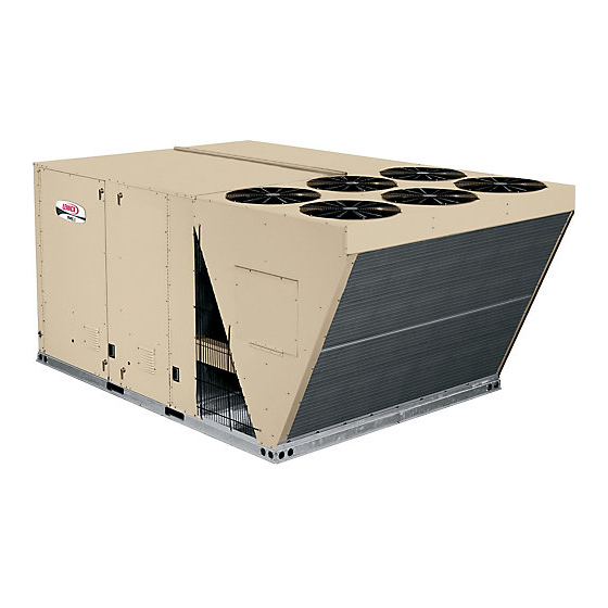
The SCA120, 240, 10 and 20 ton and SCB 288 24 ton, (35.2,
70.4 and 84.4 kW) units, are configure to order units (CTO)
with a wide selection of factory installed options. The SCA120
has a cooling capacity of 123,000 Btuh and the SCA240 has
gross a cooling capacity of 242,000 Btuh and the SCB has a
gross cooling capacity of 296,000 Btuh. All models are avai-
labe with factory installed multiple staged air volume (MSAV).
Units are designed for R410A refrigerant. See unit name-
plate. Operating pressures and pressure switch settings
are significantly higher than R22 charged units. Service
equipment must be rated for R410A.
Optional electric heat is factory installed in SCA units. Electric
heat operates in single or multiple stages depending on the
kW input size. 15 kW to 60 kW heat sections are available for
the SCA120 and 30, 60 and 90 kW heat sections are avail-
able for the SCA240/SCB288. SCA120 units utilize two com-
pressors, while SCA240/SCB288 units utilize four.
Information contained in this manual is intended for use by
qualified service technicians only. All specifications are sub-
ject to change. Procedures outlined in this manual are pre-
sented as a recommendation only and do not supersede or
replace local or state codes.
If the unit must be lifted for service, rig unit by attaching four
cables to the holes located in the unit base rail (two holes at
each corner). Refer to the installation instructions for the prop-
er rigging technique.
WARNING
Improper installation, adjustment, alteration, service
or maintenance can cause property damage, person-
al injury or loss of life. Installation and service must
be performed by a qualified installer or service
agency.
WARNING
Electric shock hazard. Can cause injury
or death. Before attempting to perform
any service or maintenance, turn the
electrical power to unit OFF at discon-
nect switch(es). Unit may have multiple
power supplies.
CAUTION
Danger of sharp metallic edges. Can cause injury.
Take care when servicing unit to avoid accidental
contact with sharp edges.
Corp. 0717−L5
Revised 10−2010
SCA/SCB
Options / Accessories
Specifications
Blower Data
. . . . . . . . . . . . . . . . . . . . . . .
Electrical / Electric Heat Data
Parts Arrangement
I Unit Components
II Placement and Installation
III Charging
. . . . . . . . . . . . . . . . . . . . . . . .
IV System Service Checks
V Maintenance
VI Accessories
VII Wiring and Operation Sequence
Page 1
SCA/SCB SERIES
10, 20 & 24 ton
35.2, 70.4 & 84.4 kW
SCA240/SCB288
Table of Contents
. . . . . . . . . . . . . . .
. . . . . . . . . . . . . . . . . . . . . .
. . . . . . . .
. . . . . . . . . . . . . . . . .
. . . . . . . . . . . . . . . . . .
. . . . . . . . .
. . . . . . . . . .
. . . . . . . . . . . . . . . . . . . . .
. . . . . . . . . . . . . . . . . . .
. . .
2007 Lennox Industries Inc.
SCA120
Page 2
Page 4
Page 8
Page 12
Page 15
Page 18
Page 36
Page 36
Page 38
Page 38
Page 39
Page 42
Litho U.S.A.
Advertisement

Subscribe to Our Youtube Channel
Related Manuals for Lennox SCA Series


Summary of Contents for Lennox SCA Series
- Page 1 ....Page 39 Take care when servicing unit to avoid accidental contact with sharp edges. VII Wiring and Operation Sequence . . . Page 42 2007 Lennox Industries Inc. Litho U.S.A. Page 1...
- Page 2 OPTIONS / ACCESSORIES Model Catalog Item Description Number Number COOLING SYSTEM Condensate Drain Trap EPDM - C1TRAP30121- 43W45 Copper - LTACDKC09/36 76M19 Corrosion Protection Condenser Section Factory Evaporator Section Factory Both Sections Factory Drain Pan Overflow Switch 60W18 ELECTRICAL Voltage 208/230V - 3 phase Factory 60 hz...
- Page 3 OPTIONS / ACCESSORIES Model Catalog Item Description Number Number INDOOR AIR QUALITY Air Filters Healthy Climate High Efficiency Air Filters MERV 8 Factory ® MERV11- C1FLTR50D-1- 97L88 MERV 15- C1FLTR50101 28W03 C1FLTR50EA1 28W02 C1FLTR50D- 28W06 Indoor Air Quality (CO ) Sensors Sensor - Wall-mount, off-white plastic cover with LCD display C0SNSR50AE1L 77N39...
- Page 4 SPECIFICATIONS 10 TON General Nominal Tonnage 10 Ton 10 Ton Data Model No. SCA120H4B SCA120H4M Blower Type Constant Air Volume MSAV (Multi-Stage Air Volume) Supply Fan Option Efficiency Type High High Cooling Gross Cooling Capacity - Btuh 123,000 123,000 Performance Net Cooling Capacity - Btuh 119,000 119,000...
- Page 5 SPECIFICATIONS 20 TON General Nominal Tonnage 20 Ton 20 Ton Data Model No. SCA240H4B SCA240H4M Blower Type Constant Air Volume MSAV (Multi-Stage Air Volume) Supply Fan Option Efficiency Type High High Cooling Gross Cooling Capacity - Btuh 242,000 242,000 Performance Net Cooling Capacity - Btuh 236,000 236,000...
- Page 6 SPECIFICATIONS 24 TON General Nominal Tonnage 24 Ton 24 Ton Data Model No. SCB288H4B SCB288H4M Blower Type Constant Air Volume MSAV (Multi-Stage Air Volume) Supply Fan Option Efficiency Type High High Cooling Gross Cooling Capacity - Btuh 296,000 296,000 Performance Net Cooling Capacity - Btuh 288,000 288,000...
- Page 7 Height: 7/8 in., Width: 3-3/4 in., Depth: 4 in. Weight 2 lbs. for IMC w/all expansion boards installed Cable Type SysBus - Lennox yellow COMM cable: C0MISC00AE1- (27M19) (500 ft. box), C0MISC04AE1- (94L63) (1000 ft. box), C0MISC01AE1- (68M25) (2500 ft. roll) ZoneBus - Lennox purple COMM cable: C0MISC05AE1- (23W99) (500 ft.
- Page 8 Page 8...
- Page 9 Page 9...
- Page 10 Page 10...
- Page 11 BLOWER DATA CONSTANT AIR VOLUME DRIVE KIT SPECIFICATIONS Nominal Maximum Model No. Drive Kit Number RPM Range 660 - 900 3.45 865 - 1080 520 - 685 240/288 5.75 685 - 865 8.63 770 - 965 MSAV™ (MULTI-STAGE AIR VOLUME) DRIVE KIT SPECIFICATIONS Nominal / Maximum Model No.
- Page 12 ELECTRICAL DATA 10 TON Model No. SCA120H4 Voltage - 60hz 208/230V-3 Ph 460V-3 Ph 575V-3 Ph Compressor 1 Rated Load Amps Locked Rotor Amps 38.9 Compressor 2 Rated Load Amps Locked Rotor Amps 38.9 Outdoor Fan Full Load Amps Motors (3) (total) (7.2) (3.9)
- Page 13 ELECTRICAL DATA 20 TON Model No. SCA240H4 Voltage - 60hz 208/230V-3 Ph 460V-3 Ph 575V-3 Ph Compressor 1 Rated Load Amps Locked Rotor Amps 38.9 Compressor 2 Rated Load Amps Locked Rotor Amps 38.9 Compressor 3 Rated Load Amps Locked Rotor Amps 38.9 Compressor 4 Rated Load Amps...
- Page 14 ELECTRICAL DATA 24 TON Model No. SCB288H4 Voltage - 60hz 208/230V-3 Ph 460V-3 Ph 575V-3 Ph Compressor 1 Rated Load Amps 22.4 10.6 Locked Rotor Amps Compressor 2 Rated Load Amps 22.4 10.6 Locked Rotor Amps Compressor 3 Rated Load Amps 22.4 10.6 Locked Rotor Amps...
- Page 15 SCA120 PARTS ARRANGEMENT FILTERS (SIX − 16 x 25 X 2") EVAPORATOR CONDENSER FANS COIL ECONOMIZER DAMPERS (OPTIONAL) BLOWER MOTOR BLOWER FILTER DRIERS CONDENSER CONDENSATE COILS DRAIN SUPPLY AIR VFD (OPTIONAL) COMPRESSORS (2) ELECTRIC HEAT (Optional) FIGURE 1 SCA240/SCB288 PARTS ARRANGEMENT EVAPORATOR CONDENSER FILTERS...
- Page 16 SCA120 CONTROL BOX PARTS ARRANGEMENT CONTACTOR COMPRESSOR 2 ECONOMIZER (K10) MODULE TRANSFORMER TRANSFORMER CONTACTOR CONTROL (A57) (T1) (T3) (K68) (A56) RELAY (K203) CONTACTOR CONTACTOR (K1) CONTACTOR (K3) (K2) TERMINAL STRIP RELAY (K65) CAPACITOR CAPACITOR CAPACITOR (TB34) (C2) (C1) (C18) TERMINAL STRIP (TB1) TERMINAL STRIP (TB24)
- Page 17 SCA240/SCB288 CONTROL BOX PARTS ARRANGEMENT ELECTRIC HEAT MODULE ECONOMIZER COMPRESSOR TERMINAL (A60) TRANSFORMER TRANSFORMER CONTROL 2 MODULE RELAY FUSE FUSE STRIP (T18) (T1) (A56) (A57) (K65) (F10) (F6) (TB34, TB35) CONTACTORS RELAY (K9) (K10) (K68) (K149) CONTACTOR (K150) (K152) ( K153) (K3) TRANSFORMER (T2)
- Page 18 I−UNIT COMPONENTS 3−Contactor Transformer T18 (SCA240/SCB288 units) ELECTROSTATIC DISCHARGE (ESD) Precautions and Procedures T18 is a single line voltage to 24VAC transformer used in all 10, 20 and 24 ton series units. Transformer T18 is CAUTION protected by a 3.5 amp circuit breaker (CB18). T18 is iden- tical to transformer T1.
- Page 19 9−Blower Contactor K3 (CAV units) ELECTRIC HEAT CONTROL HAT SECTION (45 − 90 kW electric heat only) Blower contactor K3, used in all units, is a three-pole-double- 13−Electric Heat Relay K9 break contactor with a 24VAC coil used to energize the indoor All SCA/SCB series units with 45 −...
- Page 20 16−Compressor 2 Control Module A57 18−Electric Heat Control Module A60 The compressor 2 control module A57 controls one addi- ( 45 − 90 kW electric heat) tional compressor stage for the SCA/SCB units. A57 in- The electric heat control module A60 is used to control a cludes all inputs and outputs required for compressor and second electric heat bank.
- Page 21 IMC BOARD INPUTS AND OUTPUTS SENSORS SCA240/SCB288 INPUTS P114 P115 P116 P111 P113 P110 P112 OUTPUTS COMPRESSOR SAFETY INPUTS BURNER ROOM INPUTS THERMOSTAT (A2) TB1 CONNECTS TO P110. ROOM THERMOSTAT CONNECTS TO TB1. SEE SEC- TION C2 IN THE WIRING DIAGRAM SECTION P.65 IMC AND ADD−ON BOARD LOCATION AND OPERATION 1 BLOWER REHEAT CON-...
- Page 22 SCA120 PLUMBING & COMPONENTS LOW AMBIENT LOW AMBIENT SWITCH SWITCH (S84) (S11) CONDENSER COIL LOW PRESSURE DRIERS SWITCH (S88) COMPRESSOR (B2) HIGH PRES- SURE SWITCH (S7) CRANK- CASE HEATER (HR2) 1ST STAGE COMPRESSOR (B1) BOTTOM POWER ENTRY DISCHARGE LINE HIGH PRESSURE SUCTION SWITCH LINE...
- Page 23 SCA120 REFRIGERATION CIRCUITS CONSTANT AIR VOLUME CIRCUIT 1 CIRCUIT 2 CONDENSER CONDENSER COIL COIL SCA120 REFRIGERATION CIRCUITS MSAVt SUPPLY AIR EVAPORATOR SIDE VIEW EVAPORATOR CIRCUIT 1 CIRCUIT 1 CIRCUIT 2 EVAPORATOR CONDENSER CONDENSER CIRCUIT 2 COIL COIL FIGURE 9 Page 23...
- Page 24 SCA240/SCB288 PLUMBING & COMPONENTS FREEZESTAT (ON RETURN BEND ONE FOR EACH LOW AMBIENT SWITCHES EVAPORATOR STAGE) (S11), (S84), (S85), (S94) CONDENSER COIL (ON EACH LIQUID LINE) COIL DRIERS circuit 4 VFD CONTROL circuit 3 circuit 2 circuit 1 COMPRESSOR DETAIL (typical) LOW PRESSURE SWITCHES...
- Page 25 SCA240/SCB288 REFRIGERATION CIRCUITS CONSTANT AIR VOLUME EVAPORATOR COIL STAGE 2 EVAPORATOR COIL STAGE 1 EVAPORATOR COIL STAGE 1 CONDENSER COIL STAGE 2 CONDENSER COIL SCA240/SCB288 REFRIGERATION CIRCUITS VFD SUPPLY AIR CIRCUIT 4 CIRCUIT 3 STAGE 2 EVAPORATOR COIL STAGE 1 STAGE 1 EVAPORATOR CONDENSER COIL...
- Page 26 B−Cooling Components When discharge pressure rises to 640 ± 10 psig (4413 ± 69 kPa) (indicating a problem in the system) the switch All units use independent cooling circuits consisting of sep- opens and the respective compressor is de−energized arate compressors, condenser coils and evaporator coils. (the economizer can continue to operate).
- Page 27 5−Freezestats S49 and S50 (all units) 7−Crankcase Heaters HR1 & HR2 − Thermostats S40 & S162 S53 & S95(SCA240/SCB288) Each compressor is protected by a crankcase heater and Each unit is equipped with a low temperature switch (free- thermostat. The purpose of the crankcase heater is to pre- zestat) located on the return bend of each evaporator coil.
- Page 28 C−Blower Compartment A−Blower Operation The blower compartment in all SCA120 units is located be- Initiate blower demand at thermostat according to instruc- tween the evaporator coil and the condenser coil section. tions provided with thermostat. Unit will cycle on thermostat The blower assembly is accessed by removing the screws demand.
- Page 29 BLOWER ASSEMBLY SCA120 CAV UNITS: TO INCREASE CFM LOOSEN ALLEN SCREW & TURN PULLEY CLOCKWISE TO DECREASE CFM TURN PULLEY COUNTERCLOCKWISE BELT TENSION ADJUSTING SIDE VIEW BOLTS BLOWER WHEEL BRACKET IS H−STYLE ON 20− & 25−TON UNITS BLOWER MOTOR BLOWER ASSEMBLY PULLEY SLIDING BASE REMOVE SCREWS TO...
- Page 30 Constant Air Volume (CAV) Blowers The minimum output CFM output for cooling, ventila- tion or smoke alarm mode is factory−set at 33% of fan 4− The blower RPM can be adjusted at the motor pulley. speed. The minimum can be adjusted by ECTO 0.06: Loosen Allen screw and turn adjustable pulley clock- wise to increase CFM.
- Page 31 1− Measure span length X. See figure 15. ond electric heat section. However, in the 15 and 30kW heaters, the first section houses all contactors and MEASURE BELT TENSION fuses. All contactors are equipped with a 24VAC coil. The coils in the K15 and K16 contactors are ener- gized by the main panel A55, while the coil in the K17 and K18 contactors are energized by the electric heat 2 control panel A60.
- Page 32 SCA120 ELECTRIC HEAT VESTIBULE PARTS ARRANGEMENT TERMINAL STRIP (TB3) FUSE F3 FIRST STAGE ELECTRIC SECOND STAGE ELECTRIC FUSE F3 FUSE F3 FUSE F3 F3 - 1 HEAT CONTACTOR K15 HEAT CONTACTOR K16 F3 - 4 F3−2 F3 - 3 FIGURE 16 EHA 7.5, 15, 22.5, 30, 45, 60KW ELECTRIC HEAT SECTION PARTS ARRANGEMENT HEATING ELEMENTS...
- Page 33 SCA240/SCB288 ELECTRIC HEAT VESTIBULE PARTS ARRANGEMENT TERMINAL STRIP FIRST HEAT SECTION (LEFT SIDE) (TB3) FUSE F3 FIRST STAGE ELECTRIC SECOND STAGE ELECTRIC FUSE F3 FUSE F3 FUSE F3 F3 - 1 HEAT CONTACTOR K15 HEAT CONTACTOR K16 F3 - 4 F3 - 2 F3 - 3 TERMINAL STRIP...
- Page 34 EHA 15, 30, 45, 60, AND 90 KW ELECTRIC HEAT SECTION PARTS ARRANGEMENT HEATING ELEMENTS HE1 − HE14 ELECTRIC HEAT VESTIBULE CONTROL WIRE HARNESS PRIMARY ELECTRIC HEAT LIMIT S15(1 SECTION) S107(2 SECTION) FIGURE 19 Page 34...
- Page 35 TABLE 3 SCA120 ELECTRIC HEAT SECTION FUSE RATING FUSE EHA QUANTITY VOLTAGES & SIZE F3 − 1 F3 − 2 F3 − 3 F3 − 4 208/230V 50 Amp 250V −−−−− −−−−− −−−−− 460V 25 Amp 600V −−−−− −−−−− −−−−− EHB120−15 575V 20 Amp 600V...
- Page 36 II−PLACEMENT AND INSTALLATION C−Three Phase Scroll Compressor Voltage Phasing Make sure the unit is installed in accordance with the installation instructions and all applicable codes. Three phase scroll compressors must be phased se- III−CHARGING quentially to ensure correct compressor and blower rota- tion and operation.
- Page 37 2− Check each system separately with all stages operat- TABLE 7 SCA240 CAV NORMAL OPERATING PRESSURES ing. CIRCUIT 1 CIRCUIT 2 CIRCUIT 3 CIRCUIT 4 Outdoor 3− Use a thermometer to accurately measure the outdoor Coil En- ambient temperature. tering Air psig psig psig...
- Page 38 Charge Verification − Approach Method − AHRI Testing A−Filters Units are equipped with filters as shown in table 12. Units 1− Using the same thermometer, compare liquid tempera- will accept 4" filters. Filters should be checked monthly and ture to outdoor ambient temperature. replaced when necessary with filters of like kind and size.
- Page 39 The accessories section describes the application of most of When installing either the SCA/SCB units on a combustible the optional accessories which can be factory or field installed surface for downflow discharge applications, the Lennox to the SCA/SCB units. LARMF18/36 14-inch or 24-inch (356 mm or 610mm) A−LARMF and S1CURB...
- Page 40 B−Outdoor Air Dampers (240/288 units) E−Power Exhaust Fans (all units) Dampers are manually operated to allow up to 25 percent Power exhaust fans are used in downflow applications only. outside air into the system at all times. The fans require optional down-flow gravity exhaust dampers C−Economizer (all units) and economizers.
- Page 41 F−Smoke Detectors A17 and A64 SUPPLY AIR VARIABLE FREQUENCY DRIVE Photoelectric smoke detectors are a factory installed op- tion. The smoke detectors can be installed in the supply air section (A64), return air section (A17), or in both the supply and return air section.
- Page 42 VII−Wiring Diagrams and Sequence of Operation SCA120 UNIT DIAGRAM Page 42...
- Page 43 SCA120 SEQUENCE OF OPERATION Power: 1. Line voltage from unit disconnect energizes transformer T1. T1 provides 24VAC power to terminal strip TB34. TB34 provides 24VAC to the unit cooling, heating and blower controls. 2. TB13 is also energized when unit disconnect switch closes. TB13 provides line voltage to compressors crankcase heaters, compressor contactors, the blower motor contactor (relay in MSAV units) and condenser fan relay.
- Page 44 SCA240/SCB288 UNIT DIAGRAM Page 44...
- Page 45 Sequence of Operation SCA240/SCB288 Power: 1. Line voltage from TB2 or CB10, energizes transformer 11. N.O. contacts K10−1 close energizing condenser fan B4 T1 and T18. Transformer T1 provides 24VAC power to 12. Simultaneous with step 8, 24VAC is routed through the terminal strip TB34 and T18 provides 24VAC power to compressor 2 control module A57.
- Page 46 SCA Units with MSAV and Bypass Page 46...
- Page 47 SCA Units with MSAV Page 47...
- Page 48 EHA−7.5, 15, 22.5, 30KW Y VOLT- Page 48...
- Page 49 Sequence of Operation EHA 7.5, 15, 22.5, 30W − Y, G, J and M NOTE: This sequence of operation is for all Electric SECOND STAGE HEAT: Heat kW ratings Y through J voltages. Each step of op- 5 − With the first stage heat operating, an additional heat- eration is numbered and can be followed in sequence ing demand initiates at W2 in the thermostat.
- Page 50 EHA−45, 60, 90KW − Y Page 50...
- Page 51 EHA−15, 30, 45, 60, 90 − G, J, M Page 51...
- Page 52 SEQUENCE OF OPERATION EHA−15, 30, 45, 60, 90 − Y EHA−15, 30, 45, 60, 90 − G, J and M The Y voltage diagram (A7) use elements config- SECOND STAGE HEAT: ured in a Wye. The G and J voltage diagram use With the first stage heat operating, an additional elements configured in a Delta.
- Page 53 ECONOMIZER POWER: Terminal strip TB34 energizes the economizer components with 24VAC. OPERATION: The main control module A55 along with outdoor enthalpy sensor A7 and indoor enthalpy sensor A62 (if differential enthalpy is used) communicates to the economizer control module A56 when to power the damper motor B7.
Need help?
Do you have a question about the SCA Series and is the answer not in the manual?
Questions and answers