Table of Contents
Advertisement
E2016 Lennox Industries Inc.
Dallas, Texas, USA
THIS MANUAL MUST BE LEFT WITH THE
HOMEOWNER FOR FUTURE REFERENCE
General
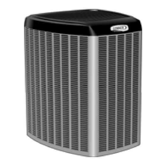
This SL18XC1 outdoor air conditioner with all-aluminum
coil is designed for use with HFC-410A refrigerant only.
This unit must be installed with an approved indoor air han
dler or coil. See the Lennox SL18XC1 Product Specifica
tions bulletin (EHB) for approved indoor component match
ups.
These instructions are intended as a general guide and do
not supersede local codes in any way. Consult authorities
having jurisdiction before installation.
NOTICE !
For more in-depth information, consult the Installa
tion and Service Procedures manual, available as
Corp. 1405-L10 on DaveNet or through the Technical
Support department at 800-453-6669.
STEP 1 -- SETTING THE UNIT -- Clearances
CLEARANCE ON ALL SIDES — INCHES (MILLIMETERS)
6 (152)
12 (305)
36 (914)
MINIMUM CLEARANCE BETWEEN TWO UNITS
NOTES:
S Clearance to access panel must be 30
CONTROL
inches (762mm).
PANEL ACCESS
S Clearance to one of the other three
LOCATION
30 (762)
sides must be 36 inches (914mm).
S Clearance to one of the remaining two
sides may be 12 inches (305mm) and
the final side may be 6 inches
(152mm).
24
(610)
INSTALLATION
INSTRUCTIONS
Dave Lennox Signature
Collection SL18XC1 System
AIR CONDITIONERS
507353-01
7/2018
Improper installation, adjustment, alteration, service or
maintenance can cause property damage, personal inju
ry or loss of life.
Installation and service must be performed by a licensed
professional installer (or equivalent) or service agency.
Before attempting to perform any service or mainte
nance, turn the electrical power to unit OFF at discon
nect switch.
ACCESS PANEL
LINE SET
CONNECTIONS
FIGURE 1
Page 1
WARNING
CAUTION
MINIMUM CLEARANCE
ABOVE UNIT
48 (1219)
REAR VIEW OF UNIT
®
Advertisement
Table of Contents

Related Manuals for Lennox SL18XC1


Summary of Contents for Lennox SL18XC1
-
Page 1: Installation Instructions
This unit must be installed with an approved indoor air han Installation and service must be performed by a licensed dler or coil. See the Lennox SL18XC1 Product Specifica professional installer (or equivalent) or service agency. tions bulletin (EHB) for approved indoor component match ups. - Page 2 STEP 1 -- SETTING THE UNIT (Continued) -- Dimensions / Placement UNIT DIMENSIONS - INCHES (MM) DISCHARGE AIR 39.40” 35.50” (1003) ELECTRICAL INLETS (902) [-030 THROUGH -042] 41 (1040) [-024, -048, -060] 47 (1194) SUCTION LINE INLET LIQUID LINE 18.60” INLET (470) 8.00”...
-
Page 3: Slab Mounting
LEG DETAIL Canadian Electrical Code (CEC). Refer to the furnace or air handler installation instructions for additional wiring application diagrams and refer to unit nameplate for minimum circuit ampacity and maximum FIGURE 4 overcurrent protection size. Page 3 SL18XC1 SERIES... - Page 4 24VAC TRANSFORMER er wiring and properly sized disconnect switch. NOTE — Units are approved for use only with cop Use the transformer provided with the furnace or air han per conductors. Ground unit at disconnect switch or dler for low‐voltage control power (24VAC - 40 VA mini connect to an earth ground.
- Page 5 (TWO-STAGE UNIT ONLY) TARGET NOTE - LINK NOT APPLICABLE TO SINGLE-STAGE UNIT. CUTTING LINK WILL HAVE NO AFFECT ON OPERATION OF SINGLE-STAGE UNITS ® CUT FOR HUMIDITROL - ENHANCED DEGREE DEHUMIFICATION ACCESSORY (EDA) TARGET (DEFAULT) APPLICATIONS. FIGURE 8 Page 5 SL18XC1 SERIES...
- Page 6 STEP 2 -- ELECTRICAL (Continued) -- Field Control Wiring The following two illustrations provide examples of control wiring connections when using a non-communicating thermostat. For examples of control wiring in complete or partial communicating systems, see the iComfortt-enabled thermostat Quick Start Guide which is provided with the thermostat. On−board link Air Handler Control ComfortSense[ 7000 Thermostats...
-
Page 7: Step 3 -- Refrigerant Piping
Take care to empty all existing traps. Polyol es IMPORTANT ! ter (POE) oils are used in Lennox units charged with HFC-410A refrigerant. Residual mineral oil can act Some scroll compressors have an internal vacuum as an insulator, preventing proper heat transfer. - Page 8 STEP 4 -- REFRIGERANT PIPING -- Removing Existing Indoor Metering Device TYPICAL EXISTING FIXED ORIFICE TYPICAL EXISTING EXPANSION VALVE REMOVAL REMOVAL PROCEDURE PROCEDURE (UNCASED COIL SHOWN) (UNCASED COIL SHOWN) STUB END TWO-PIECE PATCH PLATE LIQUID LINE DISTRIBUTOR TUBES (UNCASED COIL ONLY) ORIFICE EXPANSION LIQUID LINE ORIFICE HOUSING...
-
Page 9: Cap And Core Removal
SUCTION LINE SERVICE PORT MUST BE OPEN AND SERVICE PORT CORE REMOVED TO SUCTION ALLOW EXIT POINT FOR NITROGEN FLOW LINE SERVICE VALVE SUCTION LINE OUTDOOR INDOOR UNIT UNIT NITROGEN LIQUID LINE SERVICE LIQUID LINE VALVE FIGURE 12 Page 9 SL18XC1 SERIES... -
Page 10: Braze Line Set
CAUTION WARNING Brazing alloys and flux contain materials which are Danger of fire. Bleeding the refrigerant hazardous to your health. charge from only the high side may result Avoid breathing vapors or fumes from brazing in pressurization of the low side shell and operations. -
Page 11: Step 6 -- Installing Indoor Expansion Valve
STEP 6 -- INSTALLING INDOOR EXPANSION VALVE THIS OUTDOOR UNIT IS DESIGNED FOR USE IN SYSTEMS THAT USE A CHECK EXPANSION VALVE METERING DEVICE. SEE THE LENNOX SL18XC1 PRODUCT SPECIFICATION BULLETIN (EHB) FOR APPROVED EXPANSION VALVE KIT MATCH-UPS AND APPLICATION INFORMATION. -
Page 12: Step 7 -- Leak Test
STEP 7 -- LEAK TEST HIGH MANIFOLD GAUGE SET OUTDOOR UNIT TO SUCTION SERVICE VALVE NOTE - Position canister to deliver liquid refrigerant. NITROGEN HFC-410A CONNECT GAUGE SET Connect the high pressure hose of an HFC-410A manifold gauge set to the suction valve service port. NOTE —... - Page 13 With no leaks in the system, allow the vacuum pump to run procedure. for 30 minutes minimum at the deep vacuum level. Page 13 SL18XC1 SERIES...
-
Page 14: Homeowner Information
1. Pull system down to 28 inches of mercury (711mm Hg) Have your Lennox dealer show you where your indoor and allow pump to continue operating for an additional unit filter is located. It will be either at the indoor unit (in... -
Page 15: Pre-Service Check
This unit is equipped with an aluminum coil. Alu any time the unit is in operation. If you are unsure about the filter required for your system, call your Lennox dealer for minum coils may be damaged by exposure to solu... - Page 16 All components in the system must be functioning properly to correctly perform compressor operational check. (Accurate measurements are critical to this test as indoor system loading and outdoor ambient can affect variations between low and high capacity readings). SL18XC1 Start-Up and Performance Checklist Customer Address...
Need help?
Do you have a question about the SL18XC1 and is the answer not in the manual?
Questions and answers