Table of Contents
Advertisement
E2008 Lennox Industries Inc.
Dallas, Texas, USA
RETAIN THESE INSTRUCTIONS
FOR FUTURE REFERENCE
WARNING
Improper
installation,
service or maintenance can cause personal injury,
loss of life, or damage to property.
Installation and service must be performed by a
licensed professional installer (or equivalent) or a
service agency.
CAUTION
Physical contact with metal edges and corners
while applying excessive force or rapid motion can
result in personal injury. Be aware of, and use
caution when working near these areas during
installation or while servicing this equipment.
IMPORTANT
The Clean Air Act of 1990 bans the intentional
venting of refrigerant (CFCs, HCFCs AND HFCs) as
of July 1, 1992. Approved methods of recovery,
recycling or reclaiming must be followed. Fines
and/or
incarceration
noncompliance.
01/08
*2P0108*
adjustment,
alteration,
may
be
levied
for
INSTALLATION
INSTRUCTIONS
®
Merit
Series13ACD Units
AIR CONDITIONER UNITS
505,366M
01/08
Supersedes 11/07
Table of Contents
. . . . . . . . . . . . . . . . . . . . . . . . . . . . . . .
. . . . . . . . . . . . . . . . . . . . . . . . . . . . . . . . . .
Shipping and Packing List
Check the unit for shipping damage and listed times below
are intact. If damaged, or if parts are missing, immediately
contact the last shipping carrier.
1
Assembled outdoor unit
1
Refrigerant flow control kit (Fixed Orifice)
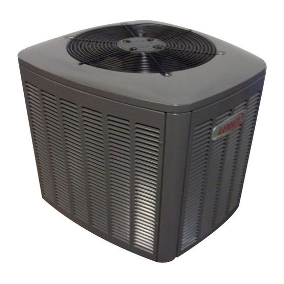
13ACD Outdoor Unit
13ACD Air Conditioners, which will also be referred to in
this instruction as the outdoor unit, uses HCFC−22
refrigerant. This outdoor unit must be installed with a
matching indoor unit and line set as outlined in the Lennox
13ACD Engineering Handbook.
This outdoor unit is designed for use in systems that use
one of the following refrigerant metering devices:
S
Thermal expansion valve (TXV)
S
Fixed orifice
Page 1
. . . . . . . . . . . . . . . . . . . . . .
. . . . . . . . . . . . . . . . . . . . . . . . . . .
. . . . . . . . . . . . . . . . . . . . . . . . . . .
. . . . . . . . . . . . . . . . .
. . . . . . . . . . . . . . . . . . .
. . . . . . . . . . . . . . . . . . .
. . . . . . . . . . . . . . . . . . . . . . . . . . .
. . . . . . . . . . . .
. . . . . . . . . . . . . . . . . . . . . . . . . . . . . .
. . . . . . . . . . . . . . . . . . . . . . . . .
. . . . . . . . . . .
. . . . . . . . . . . . . . . . . . . . . . . . .
. . . . . . . . . . . . . . .
. . . . . . . . . . . . . . . . . . . . . . . . . . . . .
. . . . . . . . . . . . . . . . . . . . . . . .
. . . . . . . . . . . . .
505,366M
*P505366M*
Litho U.S.A.
1
1
2
2
. . . . .
4
5
5
6
8
9
. . . . . . . .
9
11
12
13
13
14
18
18
19
20
Advertisement
Table of Contents

Related Manuals for Lennox Merit Series13ACD


Summary of Contents for Lennox Merit Series13ACD
-
Page 1: Table Of Contents
HCFC−22 IMPORTANT refrigerant. This outdoor unit must be installed with a matching indoor unit and line set as outlined in the Lennox The Clean Air Act of 1990 bans the intentional 13ACD Engineering Handbook. -
Page 2: Unit Dimensions
Service valve stems are factory−torqued (from 9 your supervisor. ft−lbs for small valves, to 25 ft−lbs for large valves) to Lennox Industries Inc. prevent refrigerant loss during shipping and P.O. Box 799900 handling. Using an Allen wrench rated at less than Dallas, TX 75379−9900... - Page 3 OUTDOOR UNIT (Uncased Coil Shown) TXV OR FIXED OUTDOOR ORIFICE COIL HIGH PRESSURE PRESSURE LIQUID LINE SUCTION LINE GAUGE MANIFOLD SERVICE VALVE SERVICE VALVE HFC−410A COMPRESSOR DRUM Figure 1. Typical Manifold Gauge Connection Setup Each valve is equipped with a service port which has a To Open and Close Angle−Type Service Valve: factory−installed valve stem.
-
Page 4: Recovering Refrigerant From Existing System
To Open and Close Ball−Type Service Valve: SERVICE PORT CAP A valve stem cap protects the valve stem from contamination and assures a leak−free seal. SERVICE PORT SERVICE PORT CORE 1. Remove stem cap with a wrench. OPEN TO BOTH (VALVE STEM SHOWN OPEN) INDOOR AND 2. -
Page 5: Removing Existing Outdoor Unit
METHOD 2: Use this method if the existing outdoor unit is equipped with manual shut−off valves, and plan on using new HCFC−22 refrigerant to flush the system. IMPORTANT: Some system configurations may contain higher than normal refrigerant charge due to either large internal coil volumes, and/or long line sets. -
Page 6: New Or Replacement Line Set
Field refrigerant piping consists of liquid and suction lines illustrated in figure 9. from the outdoor unit (braze connections) to the indoor unit coil (flare or braze connections). Use Lennox L15 (braze, DISCHARGE AIR non−flare) series line set, or use field−fabricated refrigerant BUILDING lines as listed in table 2. - Page 7 WOOD BLOCK Line set for heat pump applications can not be installed BETWEEN STUDS underground. For more information see the Lennox Refrigerant Piping Design and Fabrication Guidelines, or WIRE TIE contact Lennox Technical Support Product Applications INSIDE WALL for assistance.
-
Page 8: Brazing Connections
REMOVE CAP AND CORE FROM ATTACH CUT AND DEBUR BOTH LIQUID AND SUCTION GAUGES SERVICE PORTS SERVICE PORT MUST BE OPEN TO ALLOW EXIT SERVICE POINT FOR NITROGEN VALVE SUCTION LINE OUTDOOR INDOOR UNIT UNIT LIQUID LINE SERVICE VALVE FLOW NITROGEN WRAP BRAZE LINE SET NITROGEN... -
Page 9: Removing Indoor Unit Metering Device
TYPICAL TXV REMOVAL PROCEDURE Removing Indoor Unit Metering Device (Uncased Coil Shown) Remove the existing HCFC−22 refrigerant flow control TWO PIECE PATCH PLATE orifice or thermal expansion valve from the indoor coil. STUB END (UNCASED COIL LIQUID LINE ONLY) ORIFICE HOUSING REPLACEMENT PARTS DISTRIBUTOR TUBES... - Page 10 98M15 100484−45 0.099 orientation as illustrated in figure 21 using the clamp Use the Lennox catalog number to order a new or replacement fixed an screws provided. orifice kit. NOTE − Insulating the sensing bulb once installed may be The kit includes:...
-
Page 11: Testing For Leaks
−042, −048 and −060 26K35 LB−85663k On lines smaller than 7/8", mount sensing bulb Suction Line Use the Lennox catalog number to order a TXV kit. at either the 3 or 9 o’clock position. The above reference kits include: Bulb Teflon rings Bulb 1 1/4"... -
Page 12: Evacuating The System
13. Correct any leaks and recheck. WARNING 14. After leak testing disconnect gauges from service ports. Refrigerant can be harmful if it is inhaled. Refrigerant must used recovered Evacuating the System responsibly. Failure to follow this warning may result in personal WARNING injury or death. -
Page 13: Servicing Unit Delivered Void Of Charge
NOTE − A complete unit wiring diagram is located inside the unit control box cover. Figure 24. Typical Wiring Diagram 7. Shut off the dry nitrogen cylinder and remove the 4. Evacuate the system again. Then, weigh the manifold gauge hose from the cylinder. Open the appropriate amount of HCFC−22 refrigerant as listed manifold gauge valves to release the dry nitrogen from on unit nameplate into the system. -
Page 14: Start−Up And Charging Procedures
In Canada, wiring must conform with current local codes THERMOSTAT INDOOR UNIT and the current Canadian Electrical Code (CEC). POWER OUTDOOR UNIT HIGH VOLTAGE HEAT FIELD WIRING LOW VOLTAGE WIRE TIES FIELD WIRING COOLING FACTORY WIRING INDOOR BLOWER COMMON GROMMET Figure 26. - Page 15 Delta−T 1. Determine the desired DT Measure entering air temperature Temp. 24 24 24 23 23 22 22 22 20 19 18 17 16 15 of air using dry bulb (A) and wet bulb (B). DT is the intersecting value of A entering and B in the table (see triangle).
- Page 16 1. Confirm proper airflow across coil using figure START: Measure outdoor ambient temperature 2. Compare unit pressures with Table 6, Normal Operating Pressures. ABOVE 3. Use SUBCOOLING to correctly charge unit or to USE WEIGH-IN METHOD DO NOT CHARGE UNIT verify the charge is correct.
- Page 17 1. Confirm proper airflow across coil using figure 27. START: Measure outdoor ambient temperature 2. Compare unit pressures with Table 6, Normal Operating Pressures. ABOVE 3. Use SUPERHEAT to correctly charge unit or to USE WEIGH-IN METHOD Outdoor verify the charge is correct. Weigh-in or remove refrigerant Ambient 40ºF 4.
-
Page 18: System Operation
Table 6. HCFC−22 Normal Operating Pressures (Liquid +10 and Suction +5 psig) Use this table to perform maintenance checks; it is not a procedure for charging the system. Minor variations in these pressures may be due to IMPORTANT differences in installations. Significant deviations could mean that the system is not properly charged or that a problem exists with some component in the system. -
Page 19: Homeowner Information
At the beginning of each cooling season, the system IMPORTANT should be checked as follows: OUTDOOR UNIT Sprinklers and soaker hoses should not be installed 1. Clean and inspect outdoor coil (may be flushed with a where they could cause prolonged exposure to the water hose). -
Page 20: Optional Accessories
Optional Accessories or cooling. This mode is generally preferred when humidity control is a priority. The ON or CONT Refer to the Lennox 13ACD Engineering Handbook for the mode provides continuous indoor blower latest available accessories for this unit.
Need help?
Do you have a question about the Merit Series13ACD and is the answer not in the manual?
Questions and answers