Advertisement
Quick Links
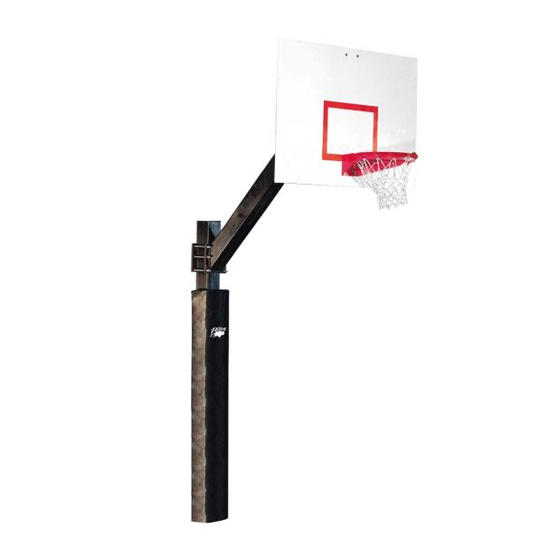
—— Installation and Safe Use Manual ——
For BA871, BA871XL, BA873, BA9873,
BA873U, BA874, BA872, BA872XL,
P A R T S L I S T
Item Qty Description
A
2
Pole Section
B
1
Pedestal Base Pole (if applicable)
C
1
Extension Arm (2 required on double sided systems)
D
1
Extension Arm Mounting Plate (not required on
double sided systems)
E
6
5/8" x 8" Hex Bolt
F
18 5/8" Hex Nut
G
14 5/8" Flat Washer
H
10 5/8" Lock Washer
I
8
3/8" x 1 1/2" Spring Pin
J
1
Backboard (model depends on system, 2 required on
double sided systems)
K
1
Rim with Net (model depends on system, 2 required
on double sided systems)
L
1
Rim Mounting Hardware (included with rim)
M
2
7/16" x 1 1/2" Carriage Bolt (4 required on double
sided systems, not required on all systems)
N
2
7/16" Flat Washer (4 required on double sided
systems, not required on all systems)
O
2
7/16" Lock Washer(4 required on double sided
systems, not required on all systems)
P
2
7/16" Hex Nut (4 required on double sided systems,
not required on all systems)
Q
4
3/8" Hex Nut (8 required on double sided systems,
not required on all systems)
Improper installation, maintenance or use may cause product failure and serious personal injury.
Inspect all contents prior to installation. Report any missing parts to dealer immediately.
Carefully read all instructions before proceeding. Pay special attention to all safety instructions.
Save the instructions in the event that the manufacturer must be contacted in the future for maintenance
Implementation Date: 6/15/2022
OL6072FX
Item Qty Description
R
S
T
U
V
W
X
Y
Z
AA
BB
CC
DD
EE
FF
GG
HH
Warning!!!
Rev: 2
N.J.C
1
4
3/8" Flat Washer (8 required on double sided systems, not
required on all systems)
4
3/8" Lock Washer (8 required on double sided systems, not
required on all systems)
1
Pole Cap
1
Pole Pad (optional on some systems)
8
1/2" x 3/4" Button Head Screw
8
1/2" Lock Washer
2
Pole Connector Bar
TBD Premix Concrete
2
1/4" x 8" Carriage Bolt
2
1/4" Wing Nut
2
Predrilled Wooden Panel
1
5/16" Hex Key
4
"J" Bolt
4
36" Rebar
1
Template
4
J-Bolt Safety Cap
1
Warning Label
File: BA871-OL6072FX.pub
Customer Service
(800) 247-7668
Ref#: 920477
Advertisement

Related Manuals for Bison BA871


Summary of Contents for Bison BA871
- Page 1 —— Installation and Safe Use Manual —— For BA871, BA871XL, BA873, BA9873, BA873U, BA874, BA872, BA872XL, OL6072FX Customer Service (800) 247-7668 P A R T S L I S T Item Qty Description Item Qty Description Pole Section 3/8" Flat Washer (8 required on double sided systems, not...
- Page 2 1. Call your local utility locating service before digging, usually by dialing 811, to avoid serious injury or service interruptions. Also avoid lawn sprinkler lines. IF YOU ARE INSTALLING A DIRECT BURY POLE SYSTEM 2a. Lay two Square Pole Sections (A) on a flat surface with drilled ends positioned as shown in Figure 1. Loosely attach two Pole Connector Bars (X) to one of the Pole Sections (A) using 1/2"...
- Page 3 5a. Using the two 1/4" x 8" Carriage Bolts (Z) and 1/4" Wing Nuts (AA), sandwich the Predrilled Wood Panels (BB) around the pole assembly at a location where the pole assembly will insert into the concrete footing. Use the set of holes that are closest to the side of the pole assembly. Position them as shown in Figure 2.
- Page 4 IF YOU ARE INSTALLING A REMOVABLE PEDESTAL MOUNT SYSTEM Dig a hole a minimum of 20" in diameter and 36" deep. Bell out the bottom 12" of the hole to a diameter that is at least 4" larger than the diameter of the hole at the top. Digging the hole too big is better than digging it too small.
- Page 5 7b. Mix the concrete according to the instructions on the bag. It is a good idea to have the concrete mixture be medium wet. This will increase your working time and allow batches to mix in the hole. Pour the hole full to ground level.
- Page 6 19. If installing a double-sided system, a second Extension Arm (C) is used instead of the Extension Arm Mounting Plate (D), but with the same hardware. See Figure 5. IF YOU ARE INSTALLING A BA871, BA871XL, BA872, or BA872XL SYSTEM 20x. Loosely attach the Backboard (J) to the previously installed Extension Arm (C) using the 7/16"...
- Page 7 IF YOU ARE INSTALLING A BA873, BA873U or BA9873 SYSTEM 20y. Remove the 3/8" Hex Nuts (Q), 3/8" Flat Washers (R) and 3/8" Lock Washers (O) that are preinstalled on the 3/8" threaded studs on the BA42RG and BA42RGU Backboard (J). 21y.