Table of Contents
Advertisement
Quick Links
Advertisement
Table of Contents

Related Manuals for Dillon GTX-Plus Series


Summary of Contents for Dillon GTX-Plus Series
- Page 1 GTX-Plus Series User’s Manual...
-
Page 2: Table Of Contents
Main Menu……………………………………………………… SETUP………………………………………………….. AUTO-OFF………………………………… PASS-FAIL………………………………… DROP LEVEL…………………………….. FILTERING………………………………… CUSTOM UNIT………………………….. AUTO AVERAGING……………………. LOAD DEFAULT………………………… SELECT OUTPUT………………………… DATABASE…………………………………………… VIEW…………………………………………. DELETE LAST…………………………… DELETE ALL……………………………… STATISTICS……………………………… CALIBRATION………………………………………. DATE & TIME………………………………………… DIAGNOSTIC………………………………………… ABOUT………………………………………………….. GTX Plus Specifications………………………………………………. Conversion Factor……………………………………………………….. GTX-Plus Series User’s Manual REV 3.0 01/03/2013... -
Page 3: Introduction
Introduction Thank you for choosing the Dillon GTX series instrument. With correct use and regular re-calibration it will give many years of accurate and reliable service. The GTX can measure tensile and compressive forces accurately, while being simple to use by the operator. -
Page 4: Powering The Gtx Plus
Battery level < 4.7 V If battery level less than 4.6 V , The “battery empty” massage will be displayed and the gauge will be powered down automatically. Important: Only use the adaptor/charger supplied. GTX-Plus Series User’s Manual REV 3.0 01/03/2013... -
Page 5: Using The Gtx Plus
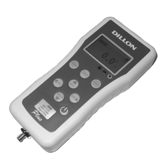
As show in Figure 1 the control panel has eight keys. Figure 1 GTX Plus control panel To power up the gauge press the ON/OFF key. A short self-test runs during which the display will show the capacity in Newtons. GTX-Plus Series User’s Manual REV 3.0 01/03/2013... -
Page 6: Basic Functions
Compression Load indicator Symbol bar of compression Figure 2 Tension and compression displays A load indicator bar alerts the operator to how much load has been applied to the load sensor. GTX-Plus Series User’s Manual REV 3.0 01/03/2013... - Page 7 See Figure 3a Track symbol Figure 3a Track Peak-Tension mode Press MODES key until the appeared on the display. The display will show the maximum tensile force. See Figure 3b GTX-Plus Series User’s Manual REV 3.0 01/03/2013...
- Page 8 Backlit Display When you press any key or applied forces to load sensor greater then 0.5 % of full scale the backlight will go on for seconds. GTX-Plus Series User’s Manual REV 3.0 01/03/2013...
- Page 9 Send Statistics of database (Max, Min, Mean, Std Dev, Cov). “d” Send database. “t” Send current date and time. “!” Send information of gauge (model, capacity, serial number, firmware revision, last calibration, original offset, current offset, overload count). GTX-Plus Series User’s Manual REV 3.0 01/03/2013...
-
Page 10: Main Menu
SETUP MENU SETUP MENU 7) SELECT OUTPUT 1) AUTO-OFF 8) LOAD DEFAULT 2) PASS-FAIL 3) DROP LEVEL 4) FILTERING 5) CUSTOM UNIT 6) AUTO AVERAGING Figure 5 Setup Menu GTX-Plus Series User’s Manual REV 3.0 01/03/2013... - Page 11 *Pass-Fail feature will PASS FAIL MENU automatically disabled if you set LOWER UPPER = and UPPER = 0 N. *LOWER must be less than the LOWER = UPPER. Press Zero key to Reset value. GTX-Plus Series User’s Manual REV 3.0 01/03/2013...
- Page 12 LOWER LEVEL = 20 N, UPPER LEVEL = 0 N Load The “OK” LED will ON. Another LED OFF. Lower level The “LOWER” LED will ON. Another LED OFF. Time Figure 7b GTX-Plus Series User’s Manual REV 3.0 01/03/2013...
- Page 13 When this feature is set ON, three addition Measure mode can be selected using the MODE key from the main display. Figure 8a 1st Peak Tension Figure 8b 1st Peak Compression 1st Peak Symbol Load currently applied Figure 8c 1st Peak Tension and Compression GTX-Plus Series User’s Manual REV 3.0 01/03/2013...
- Page 14 (e.g. to 75N), the GTX will return 75N as PEAK and 50N as 1st peak. GTX capacity 100 N 80 N Ultimate Peak 60 N First Peak 40 N 20N Drop Trigger Threshold 20 N Time Figure 9a GTX-Plus Series User’s Manual REV 3.0 01/03/2013...
- Page 15 Figure 11 Custom unit Menu To set the name, Use LEFT ARROW key to move the cursor point to NAME. Use UP and DOWN keys to change the character, press and hold to scroll change. GTX-Plus Series User’s Manual REV 3.0 01/03/2013...
- Page 16 1.6.1) START,STOP OPTION This function selects the Auto Averaging start and stop option. To access START,STOP OPTION menu, Press UP and DOWN to move the cursor point to START,STOP OPTION and press ENTER key the GTX-Plus Series User’s Manual REV 3.0 01/03/2013...
- Page 17 SETTING and press ENTER key the display will show Setting menu page. Press ESC key to return the auto averaging menu page. START,STOP OPTION START LD= 10.0 N STOP LD= 15.0 N STOP TIMER= 0010 Sec Figure 13b Setting Menu GTX-Plus Series User’s Manual REV 3.0 01/03/2013...
- Page 18 OUTPUT MENU page, Press Up and Down to move cursor point to your port and press Enter key. Press ESC key to return the setup menu page. OUTPUT MENU 1) USB OUPUT 2) PS/2 OUTPUT Figure 15 Select Output Menu GTX-Plus Series User’s Manual REV 3.0 01/03/2013...
-
Page 19: View
DELETE LAST menu, Press UP and DOWN to move the cursor point to DELETE LAST and press ENTER key the display will show delete last menu page. Press ESC key to return to database menu page. GTX-Plus Series User’s Manual REV 3.0 01/03/2013... - Page 20 20 saved records. For more than 20 records, the data should be processed by computer via Dillon’s convenient statistical software. To access STATISTICS menu, Press UP and DOWN key to move the cursor to point to STATISTICS and press ENTER key the display will GTX-Plus Series User’s Manual REV 3.0 01/03/2013...
- Page 21 UPPER LEVEL and LOWER LEVEL. 3) CALIBRATION This is used by service technicians when calibrating the gauge. Contract your Dillon distributor for details. 4) DATE&TIME This use to set date and time. To set date and time, Go to main menu page and press UP and DOWN key to move cursor...
-
Page 22: Diagnostic
If the % offset is greater than 10% please contact your supplier to arrange for load cell replacement. These values are given as an indicator only – the need for calibration/repair may vary according to the individual characteristics of the load cell. GTX-Plus Series User’s Manual REV 3.0 01/03/2013... -
Page 23: About
If gauge is used above this capacity in either tension or compression, even for a short time, permanent load cell damage can result. Overload damage is not covered by warranty. GTX-Plus Series User’s Manual REV 3.0 01/03/2013... -
Page 24: Gtx Plus Specifications
Baud rate: 38400 Digital PS2: 2 Open collector output Overload, Sample Brake PIN 1: Sample Brake Output PIN 2: Tx PIN 3: Ground PIN 4: Overload Output PIN 5: Gauge Connect Output PIN 6: Rx GTX-Plus Series User’s Manual REV 3.0 01/03/2013... -
Page 25: Conversion Factor
3.597 224.81e-3 1000 101.97e3 101.97 3597 224.81 9.807 9.807e-3 9.807e-6 0.001 35.28e-3 2.205e-3 Kg-f 9807 9.807 9.807e-3 1000 35.28 2.205 oz-f 278.01 0.27801 278.01e-6 28.345 28.345e-3 0.0625 lb-f 4448.2 4.4482 4.4482e-3 453.5 0.4535 GTX-Plus Series User’s Manual REV 3.0 01/03/2013... - Page 26 Dillon, a Weigh-Tronix Brand 1000 Armstrong drive Fairmont, Minnesota 56031 Sales (507) 238-8796 Service (507) 238-4461 www.dillonforce.com Made in Thailand GTX-Plus Series User’s Manual REV 3.0 01/03/2013...
Need help?
Do you have a question about the GTX-Plus Series and is the answer not in the manual?
Questions and answers