Advertisement
Quick Links
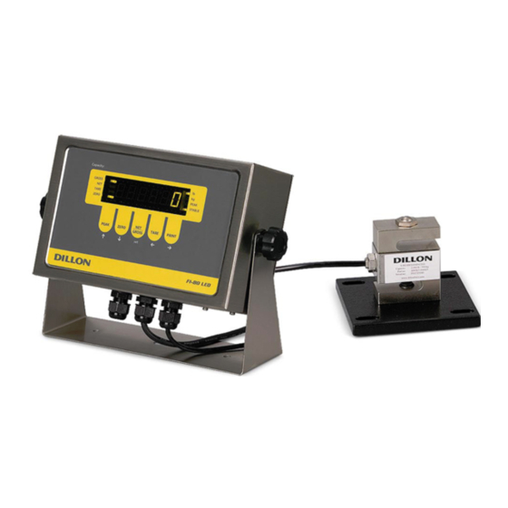
FI-80 LCD / FI-80 LED
Indicators
User's Manual
Contents subject to change without notice.
Dillon division of Avery Weigh-Tronix
1000 Armstrong Drive
Fairmont, MN 56031 USA
Sales (507) 238-8796
Service (507) 238-4461
Register your Dillon product, get manuals and see other quality force measurement products at:
www.dillonforce.com
Advertisement

Related Manuals for Dillon FI-80 LCD


Summary of Contents for Dillon FI-80 LCD
- Page 1 User’s Manual Contents subject to change without notice. Dillon division of Avery Weigh-Tronix 1000 Armstrong Drive Fairmont, MN 56031 USA Sales (507) 238-8796 Service (507) 238-4461 Register your Dillon product, get manuals and see other quality force measurement products at: www.dillonforce.com...
-
Page 2: Table Of Contents
TABLE OF CONTENTS Page Introduction to the FI-80 Series Indicator..................3 Installation ............................3 Operation ............................4 S etup / Configuration......................... 8 Appendix A: Specifications ......................A-1 Appendix B: Serial Port Information....................B-1 Appendix C: Displayed Error Codes ....................C-1... -
Page 3: Introduction To The Fi-80 Series Indicator
(included) can also be used to power the indicator. The adapter acts as the battery charger and the FI-80 LCD must use a 12 VDC, 800 mA adapter. 1. Simply plug the AC adapter into the indicator’s DC Power Jack first, and then plug into a... -
Page 4: Operation
Typically, LCD’s are used for outdoor applications while LED’s are used indoors where brightness is needed. Table 7-1 summarizes both types of display annunciators. LIQUID CRYSTAL DISPLAY (LCD) FI-80 LCD Detail LIGHT EMITTING DIODE (LED) DISPLAY FI-80 LED Display Detail... - Page 5 FRONT PANELS LED version front panel LCD version front panel FUNCTION KEYS PEAK – Toggles the indicator between normal live display mode and peak hold mode (Setup 5 must be set at “0” on the LCD version). ZERO - Sets the FI-80 to display “0” provided the following conditions are met: 1.
- Page 6 UNITS – (LCD model only) Toggles the indicator between lb and kg if enabled (A5 at “1”) and peak hold is not configured (A11 at “0”). In any other conditions, the FI-80 LCD will isplay only the default unit of measure.
- Page 7 1. All keys perform as described in the manual while in this mode. Peak-Hold Operation In Peak-Hold mode, the display updates as the load increases, but not as the load decreases. LCD version 1. Press PEAK to enter peak hold mode. The “P” annunciator appears on the left side of the display when PEAK HOLD mode is engaged and the value on screen is the peak value.
-
Page 8: S Etup / Configuration
SETUP SETUP OVERVIEW The indicator contains two main setup menus: 1. The “F” menu items configure the indicator to the attached load cell and is known as “Configuration” settings. Most of these are entered by a qualified instrumentation technician. 2. The “A” menu items configure the serial communication port and general user options. In setup mode the front panel keys become directional navigators to move around in the menus and to save the selections. - Page 9 100%√ Zero Range indicator must be in standstill to zero the scale. 1.9% FI-80 LCD extras: 1d√ Defines ‘motion’ in number of divisions of change between the Motion Band present display update and the previous display. If motion has been detected within the prior two seconds, the Print and Zero commands are disabled.
- Page 10 8√ response time. Choose 8 unless a very fast response is needed. FI-80 LCD extras: This item is for configuration by a qualified load cell indicator technician. Do not alter this value or the instrument may respond FS + 2%√...
- Page 11 1√ "0" = Disable the lb/kg key "1" = Enable the lb/kg key UNITS key This function is only relevant on the FI-80 LCD when A11 peak hold functionality is disabled. RS-232 serial port mode: "0" = Full Duplex Mode Serial Port 1√...
- Page 12 Enables “Peak Hold” mode. The display will only increment upward 0√ and the peak reading is retained. Press PEAK key to enter and exit (LCD version) the mode once active. Peak-Hold “0” = Peak Hold disabled, “3” = Peak Hold enabled Mode Note: UNITS are locked in default when A11 is enabled.
- Page 13 VIEW CALIBRATION VALUES (F18) 1. While in the Setup mode, scroll to "F 18", then scroll down once using the key to enter View Calibration menu. 2. The display will momentarily show "CAL 0" followed by a value. This value is the zero calibration value and should be recorded in the table below.
-
Page 14: Appendix A: Specifications
POWER Rechargeable Battery – FI-80 LCD 6 VDC, 3.0 Ah lead acid with 12 VDC, 800mA charger DC Power Consumption - FI-80 LCD 55mA + 15mA/350Ω Load Cell DC Power Consumption - FI-80 LED 200mA + 30mA/350Ω Load Cell ENVIRONMENTAL Operating Temperature 14°... -
Page 15: Appendix B: Serial Port Information
APPENDIX B: SERIAL PORT INFORMATION SERIAL PORT MODES B.1.1 FULL DUPLEX MODE The Full Duplex Mode provides a Demand serial transmission mode and is selected by setting A3 to “d” and A6 to “0”. The Demand mode allows control from a host device, usually a PC, and can be activated by pressing the PRINT key on the indicator’s front panel. - Page 16 B.1.1.1 RECOGNIZED HOST COMMANDS “P” - This command is sent to the indicator to print the indicated display. The indicator will not respond if the scale is in motion, positive overload or negative overload. “Z” - This command is sent to the indicator to zero the scale. The indicator will not respond if the scale is in motion, positive overload or negative overload.
- Page 17 B.1.3 SIMPLEX MODE The Simplex Mode provides a continuous serial transmission mode and is selected by setting A3 to “C” and A6 to “0”. The Continuous mode is used to interface to computers, scoreboards, and other remote devices requiring constant data updating. The transmission occurs at the end of each display update.
-
Page 18: Appendix C: Displayed Error Codes
MEANING / POSSIBLE SOLUTION Gross Overload. A load greater than the rated capacity has been applied to the scale. Remove the load and verify operation. Contact your Dillon distributor with any problems. Should not appear in normal operation. Contact your Dillon distributor. - Page 19 This equipment has been tested and found to comply with the limits for a Class A digital device, pursuant to Part 15 of the FCC Rules. These limits are designed to provide reasonable protection against harmful interference when the equipment is operated in a commercial environment. This equipment generates, uses and can radiate radio frequency energy and, if not installed and used in accordance with the instructions manual, may cause harmful interference to radio communications.
Need help?
Do you have a question about the FI-80 LCD and is the answer not in the manual?
Questions and answers