Table of Contents
Advertisement
Quick Links
Advertisement
Table of Contents

Subscribe to Our Youtube Channel
Related Manuals for Westinghouse 9K-12K


Summary of Contents for Westinghouse 9K-12K
-
Page 2: Table Of Contents
Contents Caution Statements ............................1 Composition of the Air Conditioner ......................3 Before Operation ........................4 1. Special Remarks............................4 2. Setting of Automatic Swing Louver ......................4 3. Filter Cleaning..............................5 4. Trouble Shooting............................6 Installation and Maintenance ....................7 1. Safety Notice..............................7 2. Tools and Instruments for Installation ......................8 3. -
Page 3: Caution Statements
Caution Statements Alert Symbols: DANGER : The symbol refers to a hazard which can result in severe personal injury or death. : The symbol refers to a hazard or an unsafe practice which may result in severe personal injury WARNING or death. - Page 4 Caution Statements Never use gasoline or other inflammable gas near the air conditioner, which is very WARNING dangerous. When the air conditioner operation is abnormal, such as burnt smell, deformation, fire, smoke, and so on, it is forbidden to continue using the air conditioner, the main power switch of the air conditioner must be cut off immediately and the dealer must be contacted.
-
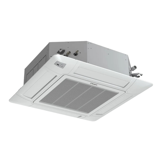
Page 5: Composition Of The Air Conditioner
Composition of the Air Conditioner Indoor unit Remote controller(optional) You can control the air-conditioner with the wired or wireless remote controller. The controller is used for controlling power ON/OFF, setting mode, temperature, fan speed and other functions. There are different types of remote controllers that can be used. Operation instructions will be further specified in remote controller's manual. -
Page 6: Before Operation
Before Operation Before Operation ● Supply electrical power to system for approximately 6 hours before start-up after long time shutdown. ● Do not start the system immediately after turning on the power supply. Doing so, it may cause a compressor failure, because the compressor is not heated well. -
Page 7: Filter Cleaning
Before Operation 3. Filter Cleaning CAUTION Do not operate the system without air filter to protect the indoor unit heat exchanger against being clogged. Turn off the main power switch before changing or cleaning filter. (The previous operation mode may appear.) 3.1 Setting the Cleaning Period of Filter Step 1... -
Page 8: Trouble Shooting
Before Operation 4.Trouble Shooting CAUTION When condensate drain overflows from the indoor unit, stop the operation and contact a qualified, licensed service professional. When you smell or see smoke coming out of the unit, turn OFF the main power supply and contact a qualified, licensed service professional. -
Page 9: Installation And Maintenance
Installation and Maintenance 1. Safety Notice WARNING ·Installation should be performed by a qualified personnel. (Improper installation may cause water leakage and damage, shock, or fire.) ·Install the unit according to the instructions given in this manual. (Incomplete installation may cause water leakage and damage, electrical shock, or fire). -
Page 10: Tools And Instruments For Installation
Installation and Maintenance The Tools and Instruments for Installation Number Tool Number Tool Standard screwdriver Knife or wire stripper Refrigerant vacuum pump Level Charge hose Hammer Pipe bender Drill Adjustable wrench Flaring kit Inner hexagon spanner and torque wrench Pipe cutter Cross head screwdriver Measuring Tape The Installation of the Indoor Unit... - Page 11 Installation and Maintenance ● Select the installation location as shown in Fig 3.2: (A) Minimum Clearance (B) Down Slope Pitch of Drain Piping:1/25~1/100 3/8 in. to 3/4 in. (10mm to 20mm) Model Capacity (Btu/h) in. (mm) 9-5/8 9K~12K (245) 9-3/4 18K~24K (248) 11-3/4...
- Page 12 Installation and Maintenance 2 Installation 1 Opening of False Ceiling and Suspension Bolts (1) Determine the final location and orientation of installation of the indoor unit. Allow adequate space for piping, wiring, and maintenance. Indoor unit installation template is printed on the packaging. Cut out the template for opening the false ceiling and installing the suspension bolts.
- Page 13 Installation and Maintenance Unit: in. (mm) Unit: in. (mm) Liquid Pipe Connection Gas Pipe Connection Drain Pipe Connection Wiring Knockout ø1-1/4(32.5) Hole (for Spare) Wiring Knockout 1-3/16 x 1-3/16(30x30) (for Cable) 9K~12K 18K~36K Fig.3.6 Indoor Unit and Air Panel 3 Mounting the Indoor Unit (1) Installing the nuts and washers to the suspension bolts Unit: in.
- Page 14 Installation and Maintenance 4 Adjusting the Space between Indoor Unit and False Ceiling Opening CAUTION ● Check the level of the drain pan using a level to avoid incorrect operation of the drain discharge mechanism in the indoor unit. The drain piping side of the indoor unit must be approximately 3/16 in.
-
Page 15: Refrigerant Pipe
Installation and Maintenance 4.Refrigerant Piping DANGER Use refrigerant R410A in the refrigerant cycle (refer to outdoor nameplate). Do not add oxygen, acetylene or other flammable and poisonous gases into the refrigerant cycle when performing a leakage test or an pressure test. These type of gases are extremely dangerous and can cause an explosion. - Page 16 Installation and Maintenance 5.Drain Piping CAUTION ● Do not create an upper-slope or rise for the drain piping, since drain water can flow back to the indoor unit causing leakage into the room when the system operation is stopped. ● Do not connect the drain pipe with sanitary, sewage piping, or any other drainage piping.
- Page 17 Installation and Maintenance (1) Prepare a polyvinyl chloride pipe with a 1-1/4 in. (32mm) outer diameter. (2) Fasten the tubing to drain hose with the adhesive agent and factory-supplied clamp. The drain piping must be performed with a down-slope pitch of 1/25 to 1/100. Upward Slope Rising part Hose Band...
-
Page 18: Condensate Drain Piping
Installation and Maintenance 6.Electrical Wiring WARNING ● Turn OFF the main power supply to the indoor and outdoor units before electrical wiring work or a periodical check is performed. ● Check to ensure that the indoor fan and the outdoor fan have stopped before electrical wiring work or a periodical maintenance is performed. -
Page 19: Trial Run
Installation and Maintenance Installation and Maintenance 6.3 Wire Routing (1) Remove the screws and the cover. (2) Pass the power supply wiring through the opening in the conduit panel. (3) Fasten the conduit connection to the conduit panel using the lock nut. (4) Connect the power supply wiring to the terminal. - Page 21 /...
- Page 35 Fig.4.2 Apriete de la tuerca c nica...
- Page 60 WESTINGHOUSE and INNOVATION YOU CAN BE SURE OF are trademarks of Westinghouse Electric Corporation. Used under license by FUJITSU GENERAL AMERICA, INC. All Rights Reserved Version No. 2021666,...
Need help?
Do you have a question about the 9K-12K and is the answer not in the manual?
Questions and answers