Table of Contents
Advertisement
Copyright
Copyright
C C
Hitachi High-Technologies
Hitachi
High-Technologies Corporation
All rights reserved. Printed in Japan.
All rights reserved. Printed in Japan.
INSTRUCTION MANUAL
INSTRUCTION MANUAL
MODEL U-2810 SPECTROPHOTOMETER
MODEL U-2810 SPECTROPHOTOMETER
(MAINTENANCE MANUAL)
(MAINTENANCE MANUAL)
Hitachi High-Technologies Corporation
Hitachi High-Technologies Corporation
Corporation 2003.
FOR
FOR
2003.
Part No. 122-9905 TS-K � � HT-HMS042068
Part No. 122-9905 TS-K
HT-HMS042068 � �
Advertisement
Table of Contents

Related Manuals for Hitachi U-2810


Summary of Contents for Hitachi U-2810
- Page 1 INSTRUCTION MANUAL INSTRUCTION MANUAL MODEL U-2810 SPECTROPHOTOMETER MODEL U-2810 SPECTROPHOTOMETER (MAINTENANCE MANUAL) (MAINTENANCE MANUAL) Hitachi High-Technologies Corporation Hitachi High-Technologies Corporation Copyright Copyright Hitachi Hitachi High-Technologies High-Technologies Corporation Corporation 2003. 2003. Part No. 122-9905 TS-K � � HT-HMS042068 HT-HMS042068 � �...
- Page 2 PREFACE PREFACE Thank you very much for Thank you very much for your purchase of Hitachi Model your purchase of Hitachi Model U-2810 U-2810 Spectrophotom Spectrophotometer. eter. The spectrophotometer is intended for use by The spectrophotometer is intended for use by persons having a...
- Page 3 IMPORTANT IMPORTANT PRECAUTIONS ON ELECTROMAGNETIC WAVE PRECAUTIONS ON ELECTROMAGNETIC WAVE INTERFERENCE INTERFERENCE 1. 1. Possible E Possible Electromagnetic lectromagnetic Wave Wave Interference Interference Caused Caused by This by This Instrument Instrument When this instrument is used in a residential area or an adjacent When this instrument is used in a residential area or an adjacent area thereto, it may cause interference to radio and television area thereto, it may...
- Page 4 WARRANTY ON PRODUCT WARRANTY ON PRODUCT The Model U-2810 Spectrophotometer is warranted to The Model U-2810 Spectrophotometer is warranted to operate operate according to the specifications given in the according to the specifications given in the instruction manual,...
- Page 5 Hitachi agent not approved or authorized by Hitachi High- High- Technologies Corporation Technologies Corporation (h) Failure d Failure due to...
- Page 6 Hitachi assumes no liability for damage to Hitachi assumes no liability for damage to data or data or application software due to failure of application software due to failure of this instrument. this instrument. Written Written Guarantee Guarantee The written guarantee on this...
- Page 7 Hitachi High-Technologies Corporation. Hitachi High-Technologies Corporation. 3. 3. Trademark Trademark Acknowledgments Acknowledgments Microsoft®...
- Page 8 SAFETY SUMMARY SAFETY SUMMARY PRECAUTIONS ON SAFETY PRECAUTIONS ON SAFETY Before using the Model U-2810 Spectrophotometer, be sure to Before using the Model U-2810 Spectrophotometer, be sure to read the following safety read the following safety instructions carefully. instructions carefully.
- Page 9 When When in in doubt, doubt, please please contact contact your local Hitachi sales representative or nearest Hitachi your local Hitachi sales representative or nearest Hitachi service office. service office. When using a che When usin g a chemical for...
- Page 10 SAFETY SUMMARY SAFETY SUMMARY This instruction manual contains the This instruction manual contains the following cautionary following cautionary instructions. instructions. WARNING WARNING Electric shock Electric shock upon upon contact contact with with hazardous hazardous voltage voltage (500 V) (500 V) Contact with the D Contact with the D lamp power supply voltage (500 V) may...
- Page 11 SAFETY SUMMARY SAFETY SUMMARY REMARKS ON SAFETY OF SPECTROPHOTOMETER REMARKS ON SAFETY OF SPECTROPHOTOMETER Electricity Electricity (a) Make Make sure th sure that the at the power power supply supply to the to the spectrophotome spectrophotometer is 100 V AC, ter is 100 V AC, 1 kVA or more (50 or 1 kVA or more (50 or 60 H...
- Page 12 SAFETY SUMMARY SAFETY SUMMARY Computer Computer Virus Virus If programs or data If programs or data is suddenly destroyed, if an is suddenly destroyed, if an unexpected unexpected operation takes place or if operation takes place or if an abnormal display appears on an abnormal display appears on the screen, your personal computer may have been the screen, your personal computer may have been...
- Page 13 SAFETY SUMMARY SAFETY SUMMARY Personal Personal Computer Computer If the personal computer is powered off during access to the If the personal computer is powered off during access to the hard disk or floppy hard disk or floppy disk, the personal computer may disk, the personal computer may become faulty or the data or software stored in it become faulty or the data or software stored in it may be...
- Page 14 SAFETY SUMMARY Warning Labels Warning Labels The warning labels shown below are attached to The warning labels shown below are attached to the Model the Model U-2810 U-2810 Spectrophotom Spectrophotometer. eter. Dangerous Dangerous Voltage Voltage (500 (500 V) High v...
- Page 15 CONTENTS CONTENTS PREFACE PREFACE ..................................................1 1 ABOUT THIS MANUAL ABOUT THIS MANUAL ..........................................1 1 IMPORTANT IMPORTANT ....................IMPORTANT-1 ....................IMPORTANT-1 PRECAUTIONS ON ELECTROMAGNETIC PRECAUTIONS ON ELECTROMAGNETIC WAVE INTERFERENCE WAVE INTERFERENCE ........IMPORTANT-1 ........IMPORTANT-1...
-
Page 16: Table Of Contents
1. 1. INSTALLATION INSTALLATION (reference (reference information information for for user) user)..........1-1 ..........1-1 Unpacking ............... 1-1 Unpacking ............... 1-1 Power Power Requirements Requirements..........1-2 ..........1-2 1.2.1 1.2.1 Power Power Supply Supply Voltage........Voltage........1-2 1.2.2 1.2.2 Frequency Frequency...... - Page 17 3. 3. INSTRUMENT INSTRUMENT CALIBRATION CALIBRATION ................3-1 ................3-1 Introduction Introduction ............3-1 ............3-1 Zero Zero %T %T Measurement Measurement ........... 3-2 ........... 3-2 Wavelength Wavelength Calibration Calibration ......... 3-2 ......... 3-2 System System Baseline Baseline Measurement Measurement ......3-3 ......3-3 4.
-
Page 18: Installation Installation
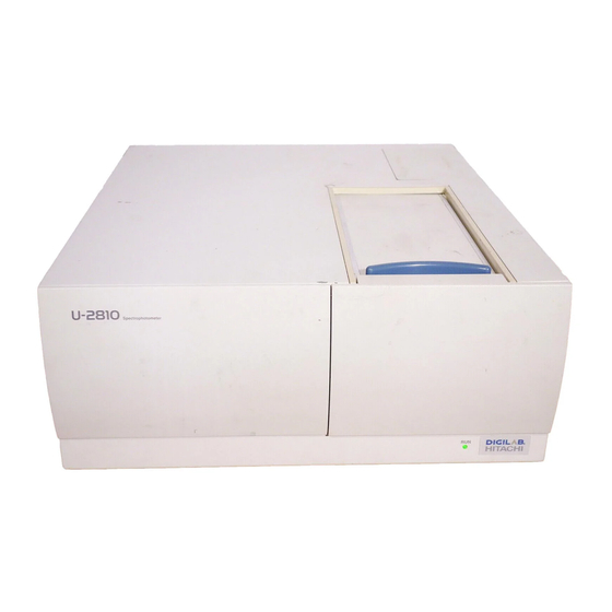
Take utmost care when taking out the instrument. Take utmost care when taking out the instrument. Figure 1-1 shows Figure 1-1 shows the Model U-2810 Spectrophotometer. the Model U-2810 Spectrophotometer. The figure is applicable to other models as well. The figure is applicable to other models as well. -
Page 19: Power Power Requirements
Power Power Requirements Requirements Power Power Requirements Requirements 1.2.1 1.2.1 Power Power Supply Supply Rated Rated voltage: voltage: 100, 100, 115, 115, 220, 220, 230 230 or or 240 240 V V AC Voltage Voltage Allowable flu Allowable fluctuation is within ±1 ctuation is within ±10% of the rated 0% of the rated voltage. -
Page 20: Installation Installation Conditions
1.3.1 1.3.1 Installation Installation Conditions Conditions Footprint: Footprint: 1120 1120 (W) (W) mm 760 (D) mm or more 760 (D) mm or more 1.3.1 1.3.1 Installation Installation Area Area × × 0 0 5 5 Personal Personal 0 0 computer computer 4 4... - Page 21 Installation Installation Conditions Conditions Other General Other General Precautions Precautions (a) The instru The instrument sho ment should not uld not be exp be exposed to osed to direct direct sunlight. sunlight. Avoid Avoid a a position position near near a a window. window.
- Page 22 Hitachi sales question, then contact your local Hitachi sales representative. representative. 1.5 Assembly 1.5 Assembly WARNING WARNING Contact with the power supply voltage (100 V) may cause Contact with the power supply voltage (100 V) may cause an electric shock, resulting in fatal or serious injury.
- Page 23 Connection Connection of of Cords Cords Connection Connection of of Cords Cords Connect cords as in Fig. 1-3. Connect cords as in Fig. 1-3. WARNING WARNING Contact with the power supply voltage (100 V) may cause Contact with the power supply voltage (100 V) may cause an electric electric shock, r shock, resulting...
-
Page 24: Voltage And And Fuse Fuse
100 V power line when a 200 V line is on a 100 V power line when a 200 V line is indicated. indicated. Fuse holder Fuse holder Fig. Fig. 1-4 1-4 Power Power Unit Unit (U-2810) (U-2810) 1 - 7 1 - 7... - Page 25 Table 1-1 Table 1-1 Model Model Voltage Voltage Fuse Fuse Capacity Capacity Part Part No. U-2810 U-2810 100 V V line line (100, (100, 115 115 V) 3.15 3.15 A A (time (time lag) lag) J821336 J821336...
-
Page 26: Power Cord Cord And And
Connection Connection of of Power Power Cord Cord and and Grounding Grounding Wire Wire WARNING WARNING Contact with the power supply voltage (100 V) may cause Contact with the power supply voltage (100 V) may cause an electric shock, resulting in fatal or serious injury. an electric shock, resulting in fatal or serious injury. -
Page 27: Printer
Connection Connection of of Printer Printer Connection Connection of of Printer Printer Use a printer which is Use a printer which is compatible with the Windows XP. compatible with the Windows XP. Printer connection differs depending on the model of Printer connection differs depending on the model of printer. -
Page 28: Uv Solutions Solutions Program Program
1.11 1.11 1.11 1.11 Turning Turning On On Power Power Turn on the power Turn on the power supply in the following procedure. supply in the following procedure. Turn on Turn on the the power power switch switch of of the the printer. -
Page 29: Instrument
1.13 1.13 Shutdown Shutdown of of Instrument Instrument 1.13 1.13 Shutdown Shutdown of of Instrument Instrument Upon completion of measurement, shut down the instrument in Upon completion of measurement, shut down the instrument in the following procedure. the following procedure. From the From the File... -
Page 30: Configuration
Figure 2-1 shows the appearance of the instrument . instrument . Data processing unit Data processing unit Spectrophotometer Spectrophotometer (personal computer) (personal computer) main unit main unit Fig. 2-1 Fig. 2-1 Appearance Appearance of of Model Model U-2810 U-2810 Spectrophotomet Spectrophotometer er 2 - 1 2 - 1... -
Page 31: Function Of Of Each Each Part Part
(1) Sample (1) Sample compartment compartment (2) RUN lamp (2) RUN lamp Fig. Fig. 2-2 2-2 Appearance Appearance of of Model Model U-2810 U-2810 Spectrophotomete Spectrophotometer Main r Main Unit Unit (1) Sample Sample Compartment Compartment In this compartment, In this... - Page 32 (toward front) (toward front) (3) ACC connector (3) ACC connector Fig. Fig. 2-3 2-3 Left Left Side Side of of Model Model U-2810 U-2810 Spectrophotomete Spectrophotometer Main r Main Unit Unit ACC connector connector (I/O) (I/O) Used for input/output of signals for control of the auto...
- Page 33 2.3 Application 2.3 Application Application Application The spectrophotometer is utilized for absorption analysis of liquid, The spectrophotometer is utilized for absorption analysis of liquid, solid and gaseous samples in solid and gaseous samples in the ultraviolet-visible region. the ultraviolet-visible region. Figure 2-5 shows the scheme of Figure 2-5 shows the scheme of Bouguer-Bee Bouguer-Beer’s law.
- Page 34 Optical path length Optical path length Transparent nt cell Transpare cell Liquid Liquid Monochromatic Monochromatic beam beam Concentration Concentration Fig. Fig. 2-5 2-5 Bouguer-Beer’s Bouguer-Beer’s Law 2 - 5 2 - 5...
- Page 35 Operating Operating Principle Principle Operating Operating Principle Principle Figure 2-6 shows the optical system Figure 2-6 shows the optical system of the Model U-2810 of the Model U-2810 2.4.1 2.4.1 Optical Optical System System Spectrophotometer. Spectrophotometer. The white light emitted from the light source is fed to...
- Page 36 2.4.2 2.4.2 Toroidal Toroidal lamp lamp diffraction diffraction grating grating Condensing Condensing Exit slit Exit slit Entrance Entrance mirror mirror slit slit WI lamp WI lamp Filter Filter Plane Plane mirror mirror Detector 2 Detector 2 Reference Reference Lens 2 Lens 2 Half Half...
-
Page 37: Use Of Of Spectrophotomet Spectrophotometer
Proper Proper Use Use of of Spectrophotome Spectrophotometer Proper Proper Use Use of of Spectrophotometer Spectrophotometer When selecting a solvent for When selecting a solvent for sample preparation, keep the sample preparation, keep the 2.5.1 Selection 2.5.1 Selection of of following requirements in mind. -
Page 38: Function
2.6.1 2.6.1 Measurement Measurement Function Function 2.6.1 Measurement 2.6.1 Measurement With the UV With the UV Solutions program, the following measureme Solutions program, the following measurement nt Mode Mode modes are available. modes are available. Quantitative Quantitative calculation calculation • • Wavelength Wavelength scan scan... - Page 39 Measurement Measurement Function Function Statistic Calculation Statistic Calculation Mean value, standard deviation (SD) Mean value, standard deviation (SD) Judgment of of Upper Judgment Upper and and Lower Lower Limits Limits (1) The scan The scan speed is speed is settable in settable in a range o a range of 10 to 360 f 10 to 3600 nm/min.
-
Page 40: Baseline Correction
2.6.6 2.6.6 Spectrum Spectrum calculation calculation • • Fundamental arithmetic operation Fundamental arithmetic operations can be s can be made on spectra, made on spectra, and multiplication can be performed using a multiple of and multiplication can be performed using a multiple of a a coefficient of displayed spectrum. - Page 41 2.7 Specifications 2.7 Specifications 2.7 Specifications 2.7 Specifications Table 2-2 shows the specifications of Table 2-2 shows the specifications of the Model U-2810. the Model U-2810. Table Table 2-2 2-2 Specifications Specifications of of Model Model U-2810 U-2810 Monochrom Monochromator...
- Page 42 3. 3. INSTRUMENT CALIBRATION INSTRUMENT CALIBRATION 3.1 Introduction 3.1 Introduction This section describes how to calibrate the This section describes how to calibrate the instrument. instrument. 0%T measurement is intended for calibration in the 0%T measurement is intended for calibration in the ordinate ordinate direction.
-
Page 43: Zero Zero %T %T Measurement Measurement
Zero Zero %T %T Measurement Measurement Zero Zero %T %T Measurement Measurement This is a function for correcting the 0%T line. This is a function for correcting the 0%T line. For zero %T For zero %T measuremen measurement, take t, take the following procedure. the following procedure. -
Page 44: System System Baseline Baseline Measurement Measurement
Set Set the parameters as shown below and save the parameters as shown below and save the baseline. baseline. Parameter Parameter Setting for Setting for U-2810 U-2810 Start Start WL WL (nm) (nm) 1100 1100 End WL WL (nm) -
Page 45: Maintenance Maintenance And And Inspection Inspection
4.3.1 4.3.1 4. 4. MAINTENANCE MAINTENANCE AND AND INSPECTION INSPECTION 4.1 Introduction 4.1 Introduction The spectrophotom spectrophotometer eter requires requires maintenance. maintenance. This This section section gives information on daily inspection and diagnosis functions. gives information on daily inspection and diagnosis functions. Self-diagnosis Self-diagnosis and and Automatic... - Page 46 Check Check of of Specified Specified Performance Performance Table Table 4-1 4-1 Instrument Instrument Tab Parameter Parameter Setting Setting Data Data mode mode E(S) E(S) Start Start Wavelength Wavelength (nm) (nm) End Wavelength Wavelength (nm) (nm) Scan Scan speed speed (nm/min) (nm/min) Response Response...
- Page 47 Hitachi service office. then contact Hitachi service office. (12) (12) The analytical p The analytical parameters can be s arameters can be stored as an analys tored as an analysis is method file.
-
Page 48: Check Of Of Specified Check Specified Performance Performance
1.0 to 1.5 nm 1.0 to 1.5 nm for the for the Model Model U-2810, U-2810, it is it is normal. normal. If the If the width is out of the range, then execute wavelength width is out of the range, then execute wavelength calibration and retry measurement for check. - Page 49 4.3.3 4.3.3 Table Table 4-5 4-5 Instrument Instrument Tab Parameter Parameter Setting Setting Data Data mode mode Start Start Wavelength Wavelength (nm) (nm) End Wavelength Wavelength (nm) (nm) Scan Scan speed speed (nm/min) (nm/min) Response Response Medium Medium Baseline Baseline correction correction User User...
-
Page 50: Flatness
If the If the specified specified performance performance is is not obtained, then contact Hitachi service office. not obtained, then contact Hitachi service office. The analytical analytical parameters parameters can can be be stored... -
Page 51: Periodical Periodical Maintenance Maintenance
4.4.1 4.4.1 Periodical Periodical Maintenance Maintenance The sample sample compartment compartment is is susceptible susceptible to to contamination. contamination. It is It is 4.4.1 Cleaning 4.4.1 Cleaning of of recommende recommended to clean the d to clean the sample compartment if sample is spilt. sample compartment if sample is spilt. - Page 52 Periodical Periodical Maintenan Maintenance Remove the retaining Remove the retaining screw with the furnished screw with the furnished Phillips screwdriver. Phillips screwdriver. Holder base Holder base Fig. Fig. 4-5 4-5 Detachment Detachment of of Holder Holder Base Base Specimen chamber Specimen chamber bottom plate bottom plate...
- Page 53 4.4.2 4.4.2 If the t If the transparent window of the sample compartment is ransparent window of the sample compartment is 4.4.2 4.4.2 Cleaning Cleaning of of contaminated contaminated, deta , detach ch and and clean clean the the window. window.
-
Page 54: Check Of Of Lamp Check Lamp On On Time Time
This This function function is p is provided rovided with with the M the Model odel U-2810 U-2810 Spectrophotometer. Spectrophotometer. For check, select the For check, select the Lamp Usage command from the Lamp Usage command from the Spectrophoto Spectrophotometer meter menu. -
Page 55: After After Completion Completion Of Of Measuremen Measurement T
4.6.1 4.6.1 4.6 Storage 4.6 Storage Turn off the Turn o ff the POWER POWER switch switch and and pull pull out the out the plug plug from th from the e 4.6.1 4.6.1 After After Completion Completion power outlet. power outlet. - Page 56 Execute the zero %T Execute the zero %T measurement and calibrate measurement and calibrate wavelength. wavelength. Contact Contact the nearest Hitachi High- nearest Hitachi High- Technologies Corporation agent Technologies Corporation agent if the error message is if the error message is displayed displayed again.
-
Page 57: Replacement Replacement Parts Parts
. To p To prepare repare spare spare parts, parts, contact your local Hitachi sales representative or nearest Hitachi contact your local Hitachi sales representative or nearest Hitachi service office. service office. WI lamp....P/N 122-2301 WI lamp....P/N 122-2301 lamp lamp ....P/N 122... - Page 58 Replacement Replacement of of Light Light Source Source Lamp Lamp Replacement Replacement of of Light Light Source Source Lamp Lamp WARNING WARNING Cautions on lamp Cautions on lamp replacement! replacement! The p The power ower voltage voltage (500 (500 V) of V) of the D the D lamp could cause...
- Page 59 Replacement nt of of WI Replaceme WI Lamp Lamp Loosen and Loosen and pull pull out the out the retainer retainer spring. spring. Push Push in a in a new lamp to the extreme end of the lamp holder. lamp to the extreme end of the lamp holder. WI lamp WI lamp Fig.
-
Page 60: Replacement Of Of Light Replacement Light Source Source Lamp Lamp
Replacement Replacement of of Light Light Source Source Lamp Lamp (c) Attach Attach a a new new D D lamp by lamp by reversing the procedure reversing the procedure described above. described above. (d) Plug Plug in in the the D D lamp connector as shown in Fig. - Page 61 INDEX INDEX A A ASCII text file ASCII text file .............................. 2-11 2-11 Baseline flatness Baseline flatness........................2-12, 2-12, 4-4 Baseline stability Baseline stability ............................ 2-12 2-12 Bouguer-Beer’s Bouguer-Be...
- Page 62 Installation........Installation.......................... 1-1 Instrument calibration......Instrument calibration....................3-1 Instrument configuration Instrument configuration........................2-1 Instrument tab Instrument tab ..........................4-2, 4-2, 4-5 JCAMP-DX file JCAMP-DX file ......
- Page 63 RUN lamp......... lamp..........................2-2 Replacement of Replaceme nt of light so light source la urce lamp..mp................5-2 Report Report tab tab .............................. 4-3, 4-3, 4-6 Rescaling Rescaling ............
Need help?
Do you have a question about the U-2810 and is the answer not in the manual?
Questions and answers