Advertisement
Quick Links
MAINTENANCE
INFORMATION
Introduction
Description of compressor parts
Maintenance
Checking the oil level
Storage of Compressor
Changing the oil
Microfilter element change
Valve Inspection
Unloader system inspection
Cooler inspection
Starting compressor after Maintenance
General maintenance notes
Troubleshooting
Low output flow or pressure
Blowing safety Valves
Leakage from HP receivers
Low oil pressure
Knocking
Rumbling
Diagrams
Fig 1 - Compressor, complete
Fig 2 – Crankcase
Fig 3 – Crankcase
Fig 4 – Piston and connecting rod
July 21
VP30/VP500 Compressor
VP30/VP500
MAINTENANCE INFORMATION
1 of 42
Advertisement

Subscribe to Our Youtube Channel
Related Manuals for MAXIMATOR VP30

Summary of Contents for MAXIMATOR VP30
- Page 1 VP30/VP500 MAINTENANCE INFORMATION MAINTENANCE INFORMATION VP30/VP500 Compressor Introduction Description of compressor parts Maintenance Checking the oil level Storage of Compressor Changing the oil Microfilter element change Valve Inspection Unloader system inspection Cooler inspection Starting compressor after Maintenance General maintenance notes...
- Page 2 VP30/VP500 MAINTENANCE INFORMATION Fig 5 – 1st Stage Cylinder Fig 6 – 2nd Stage Cylinder Fig 7 – 3rd Stage Cylinder Fig 8 – Fan and guard Fig 9 – Coolers Fig 10 – Unloader Manifold Fig 11 – Unloaders Fig 12 –...
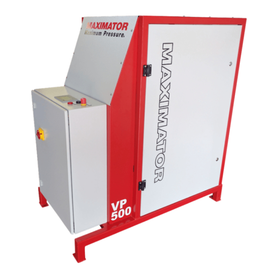
- Page 3 Parts lists • Drawings The VP30 (also referred to as VP500) compressor is a Three Stage reciprocating Air cooled compressor with a maximum working pressure of 350 Bar (5000 psi). Lubrication is by Integral crankshaft driven oil pump to crankshaft and big end bearings and by splash/oil mist to the cylinder bores and small end bearings.
- Page 4 VP30/VP500 MAINTENANCE INFORMATION Description of compressor parts Compressor Stages The Compressor takes gas from the suction vessel at approximately 6 BarG and compresses it in three stages up to a maximum of 350 Bar (5000 psi). Three stages of compression are used together with the intercoolers, to reduce the temperatures at each stage of compression.
- Page 5 VP30/VP500 MAINTENANCE INFORMATION Unloaders Every time the compressor stops, gas pressure is retained in the cylinders and coolers of each stage. This gas pressure must be vented to allow the compressor to be started ‘off-load’. The unloader system is an automatic system for venting this pressure. The system is operated by oil pressure from the lubrication system, which prevents the gas from each stage from venting to the unloader vent.
- Page 6 VP30/VP500 MAINTENANCE INFORMATION Oil sight glass The oil sight glass is used to check the oil level in the compressor sump. It is essential that the oil level is checked regularly and kept between the minimum and maximum marks. Failure to maintain the correct oil level will result in failure of the compressor: ●...
-
Page 7: Maintenance
VP30/VP500 MAINTENANCE INFORMATION Maintenance It is essential that regular maintenance is carried out. During operation of the compressor, carbon deposits will build up on the compressor valves. If the maintenance is not carried out in accordance with the instructions in this manual, these deposits can cause loss of performance and damage to pistons and cylinders. - Page 8 VP30/VP500 MAINTENANCE INFORMATION Microfilter element change The Microfilter has a replaceable element (Part number 163140). The “O” ring 169531 and the disc 101184 should be replaced together with the element. To change the element, the compressor must be stopped: Unscrew the locking grub screw 2 turns.
-
Page 9: Valve Inspection
VP30/VP500 MAINTENANCE INFORMATION Valve Inspection Make sure that the compressor is stopped and the power is isolated before carrying out this work. Valve Cleaning Note: do not dismantle valve assemblies for cleaning purposes. Parts within the assembly can be easily damaged. - Page 10 VP30/VP500 MAINTENANCE INFORMATION If the valve plate assembly 6/11 is excessively worn it must be replaced. Reassemble in reverse order, fitting new gaskets. When reassembling, lubricate every component (except gaskets) with clean lubricating oil. On reassembly, tighten the cylinder head screws to the correct torque loading.
- Page 11 VP30/VP500 MAINTENANCE INFORMATION Identifying screw head type, e.g. 8.8 and 10.9 See marking on the screw head to determination the correct maximum torque setting. Unloader system inspection General Disassembly Before the unloader blocks can be re-moved from the compressor, the pipes to them must be removed.
-
Page 12: Troubleshooting
VP30/VP500 MAINTENANCE INFORMATION Starting compressor after Maintenance Turn the compressor by hand for a few revolutions. Check that the motion is smooth and free. Re-check all screws and connections for tightness. Run the compressor for 10 - 15 minutes until warm. -
Page 13: Low Oil Pressure
VP30/VP500 MAINTENANCE INFORMATION Blowing safety Valves Possible reasons for safety valves blowing are given below. In addition to these reasons, it may be possible that the safety valves themselves can be faulty. Safety valve adjustments may change due to vibration, or the valve may be worn. - Page 14 VP30/VP500 MAINTENANCE INFORMATION Rumbling A deep rumbling sound can indicate that the main bearings 3/17 and 3/8 are worn. Check the crankshaft wear by pulling the shaft from side to side. No movement should be detectable. Diagrams FIGURE DETAILS MANUAL PAGE...
- Page 15 VP30/VP500 MAINTENANCE INFORMATION Fig 2 – Crankcase July 21 15 of 42...
- Page 16 VP30/VP500 MAINTENANCE INFORMATION Fig 2 – Crankcase, parts list POS. PART NUMBER DESCRIPTION QUANTITY 161901 CRANK CASE 139491 STUD M12 X 30 094471 SPRING WASHER D12 080764 NUT M12 162027 RETAINING RING 85 X 3 162235 EXTENSION 1" X 100...
- Page 17 VP30/VP500 MAINTENANCE INFORMATION Fig 3 – Crankcase July 21 17 of 42...
- Page 18 VP30/VP500 MAINTENANCE INFORMATION Fig 3 – Crankcase – parts list Pos. Part Number Description Quantity 196913 crankshaft 139459 feather key 6 x 6 x 22 139467 feather key 5 x 5 x 5 197973 feather key 12 x 8 x 45...
- Page 19 VP30/VP500 MAINTENANCE INFORMATION Fig 4 – Piston and connecting rod July 21 19 of 42...
- Page 20 VP30/VP500 MAINTENANCE INFORMATION Fig 4 – Piston and connecting rod – parts list Pos. Part Number Description Quantity 162021 CONNECTING ROD CPL. 519239 PISTON CPL. 50/70 148962 PISTON RING M50X45,8X2,5 197829 PISTON CPL. 27/70 198276 PISTON RING M 27X24,6X2 519676 PISTON CPL.
- Page 21 VP30/VP500 MAINTENANCE INFORMATION Fig 5 – 1 Stage Cylinder July 21 21 of 42...
- Page 22 VP30/VP500 MAINTENANCE INFORMATION Fig 5 – 1 Stage Cylinder – parts list Pos. Part Number Description Quantity 162032 O-ring 100 x 2 161922 guide cylinder 094471 spring washer D12 080764 nut M12 004286 stud M10 x 25 181429 cylinder d50...
- Page 23 VP30/VP500 MAINTENANCE INFORMATION Fig 6 – 2 Stage Cylinder July 21 23 of 42...
- Page 24 VP30/VP500 MAINTENANCE INFORMATION Fig 6 – 2 Stage Cylinder – parts list Pos. Part Number Description Quantity 162032 O-RING 100 X 2 161922 GUIDE CYLINDER 094471 SPRING WASHER D12 080764 NUT M12 004286 STUD M10 X 25 073440 O-RING 70 X 2...
- Page 25 VP30/VP500 MAINTENANCE INFORMATION Fig 7 – 3 Stage Cylinder July 21 25 of 42...
- Page 26 VP30/VP500 MAINTENANCE INFORMATION Fig 7 – 3 Stage Cylinder – parts list Pos. Part Number Description Quantity 162032 O-RING 100 X 2 161922 GUIDE CYLINDER 004294 STUD M10X30 073440 O-RING 70 X 2 094463 SPRING WASHER D10 080772 NUT M10...
- Page 27 VP30/VP500 MAINTENANCE INFORMATION Fig 8 – Fan and guard July 21 27 of 42...
- Page 28 VP30/VP500 MAINTENANCE INFORMATION Fig 8 – Fan and Guard – parts list Pos. Part Number Description Quantity 156710 cover 138800 washer D6,4 002275 screw M 6x12 001368 screw M6 x 25 094447 spring washer D6 163602 fan blade type E 189...
- Page 29 VP30/VP500 MAINTENANCE INFORMATION Fig 9 – Coolers July 21 29 of 42...
- Page 30 VP30/VP500 MAINTENANCE INFORMATION Fig 9 – Coolers – parts list Pos. Part Number Description Quantity 162043 pipe 15,0 x 1,5 025003 pipe 12,0 x 1,5 163292 pipe 8,0 x 1,5 162176 fitting EVW 15 LR 069028 fitting EVT 8 PSR...
- Page 31 VP30/VP500 MAINTENANCE INFORMATION Fig 10 – Unloader Manifold July 21 31 of 42...
- Page 32 VP30/VP500 MAINTENANCE INFORMATION Fig 10 – Unloader Manifold – parts list Pos. Part Number Description Quantity 163616 ARMATURE BLOCK 197838 FITTING GE 6-L / R1/4 027820 GASKET RING A14X18 CU 001155 LOCKING SCREW R1/4 148687 SILENCER G1/2 096768 NOZZLE D2 / M5 096610 DISCHARGE VALVE CPL., 1ST STAGE...
- Page 33 VP30/VP500 MAINTENANCE INFORMATION 170426 FITTING GE 8PSR 3/8 069035 FITTING EVW 8 L 169797 NON RETURN VALVE RHV 8SR 027871 GASKET RING A 21X26 CU 030872 GASKET RING 21,5X28,7X2,5 191068 FITTING SWVE 6SR 103128 NON RETURN VALVE RHD 6S 191069...
- Page 34 VP30/VP500 MAINTENANCE INFORMATION Fig 11 – Unloaders July 21 34 of 42...
- Page 35 VP30/VP500 MAINTENANCE INFORMATION Fig 11 – Unloaders – parts list Pos. Part Number Description Quantity 096610 discharge valve cpl., 1st stage 096423 discharge valve cpl. 096628 screw M5x30 096660 housing cover 096679 cover gasket 096210 Lip sealing ring 32x24x7x6 129933...
- Page 36 VP30/VP500 MAINTENANCE INFORMATION Fig 12 – Oil Lubrication July 21 36 of 42...
- Page 37 VP30/VP500 MAINTENANCE INFORMATION Fig 12 – Oil Lubrication – parts list Pos. Part Number Description Quantity 162057 connecting piece 197840 fitting Ge 6-Zlr 162025 fitting RHV 6 LR 125407 spring washer D5 000230 screw M5 x 60 33693 ball valve...
- Page 38 VP30/VP500 MAINTENANCE INFORMATION Fig 13 – Crankcase Breather July 21 38 of 42...
- Page 39 VP30/VP500 MAINTENANCE INFORMATION Fig 13 – Crankcase Breather – parts list Pos. Part Number Description Quantity 514494 filter 082970 fitting GE 12 LR 1/4" 082988 fitting GE 12 LR 1/2" 068101 tube socket 1/2 x 1/2 189711 non return valve 163287 fitting GE 12 LR 1/2"...
- Page 40 VP30/VP500 MAINTENANCE INFORMATION Fig 14 – Motor July 21 40 of 42...
- Page 41 VP30/VP500 MAINTENANCE INFORMATION Fig 14 – Motor – parts list Pos. Part Number Description Quantity 197850 motor 158054 screw M10 x 40 094463 spring washer D10 197849 socket-taper 197845 v-belt pulley D=132 080772 nut M10 196925 motor base 196926 motor base...
- Page 42 VP30/VP500 MAINTENANCE INFORMATION Fig 15 - Microfilter 169531 101184 163140 July 21 42 of 42...
Need help?
Do you have a question about the VP30 and is the answer not in the manual?
Questions and answers