
Related Manuals for MAXIMATOR DLE 5

Summary of Contents for MAXIMATOR DLE 5
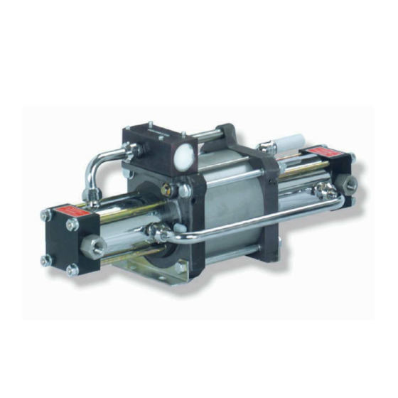
- Page 1 Operating, maintenance and repair instructions for ® MAXIMATOR Compressors DLE 5 MAXIMATOR GmbH Walkenrieder Straße 15 37449 Zorge Phone: +49-55 86-80 30 E-Mail: Info@maximator.de Homepage: www.maximator.de Fax: +49-55 86-8 03 40...
-
Page 2: Table Of Contents
1 Index Index _________________________________________________________ 2 Mode of operation _______________________________________________ 3 Safety instructions _______________________________________________ 4 Usage to the intended purpose _________________________________ 4 Emission___________________________________________________ 4 Safety hazards ______________________________________________ 4 Safety at the place of assembly _________________________________ 5 Technical data __________________________________________________ 5 Dimension drawing___________________________________________ 5 Mounting ______________________________________________________ 7 Assembly __________________________________________________ 7 Compressed air system _______________________________________ 7... -
Page 3: Mode Of Operation
2 Mode of operation As a rule, the MAXIMATOR compressors operate according to the pressure intensifier principle: large surface area with a low pressure (air piston(3)) small surface area with a high pressure (HP piston(2)). A continual flow is attained by continuous pulsation. -
Page 4: Safety Instructions
3 Safety instructions MAXIMATOR compressors are manufactured to the latest state of the art and are safe to operate. However, there are potential hazards in case of inadvertent wrong operation or wrong use: • For the health and lives of persons. -
Page 5: Safety At The Place Of Assembly
3.4 Safety at the place of assembly MAXIMATOR compressors must not be operated in closed containers, since the discharged drive air may burst the container. The high-pressure bolted connections at the suction and pressure sockets must not be unscrewed, even if this would facilitate the erection of the compressor. The bolted connections must be firmly tightened in order to avoid any leakages and damage. -
Page 7: Mounting
The remedy is re-lubrication with MAXIMATOR grease. If a compressed air oiler is used, the oil content of the air should be 1mg/m³ to 5mg/m³. -
Page 8: Direct Pilot Valve Air
5.2.4 Direct pilot valve air The compressors are designed for operation with direct pilot valve air which should be connected downstream of the pressure controller, if applicable. Thus, the pump can reverse better with small drive pressures. The compressor does not operate unless the direct pilot valve air is connected. -
Page 9: Maintenance
Even smallest impurification may cause serious damage at the precision-machined pneumatic components. All individual pump and compressor parts are available from MAXIMATOR as spare parts. The respective purchase order numbers can be gathered from the drawings attached to each compressor. Typically, there is more than one sealing defective or worn out, hence, we have compiled different sealing kits. -
Page 10: High-Pressure Sealing Repair
8.1 High-pressure sealing repair 8.1.1 Dismantling Loosen the four hexagon nuts from the stud bolts. Carefully separate the compressor head by means of light taps with a plastic hammer from the HP cylinder. Loosen the HP cylinder by means of light taps with a plastic hammer from the top cover. - Page 11 Remove the retaining pin of the castle nut. Loosen the castle nut. If the HP piston follows to turn, it is recommended to use an impact screwdriver to loosen the castle nut. Remove the piston disk. Remove the piston sealing ring and O ring from the HP piston.
- Page 12 Draw the HP piston from the piston rod. Remove the O ring from the HP piston. Remove the O rings of the HP head. Dismantle the O ring that seals the HP cylinder.
-
Page 13: Hp Piston Assembly
Clean all re-used components and inspect them for any damage. Slightly grease all sealing and guide elements. Use preferably MAXIMATOR grease Works No. 3610.1456. Grease the top and bottom cover the O rings that seal the HP part and assemble the rings (first and second stage). - Page 14 Grease the O ring and mount it into the HP piston. Grease the HP cylinder. Insert the piston sealing ring into the HP cylinder and align the ring parallel ca. 13 mm below the cylinder edge. Push the HP cylinder over the HP piston until the piston sealing ring fits close to the O ring.
- Page 15 Attach the piston disk. Attach the spring lock washer and the castle groove. Tighten the castle groove with 25 Nm. The piston sealing ring is pushed onto the O ring during tightening. Use the retaining pin to secure the castle nut (appropriately bend the retaining pin with a screwdriver).
-
Page 16: Hp Cylinder Assembly
8.1.3 HP cylinder assembly Push the HP cylinder over the O ring of the top cover till to the stopper. Caution: Make sure not to damage the O ring. Grease and mount the O rings that seal the HP head. - Page 17 Push the compressor head over the stud bolts. Make sure that the suction and pressure lines can be mounted without any warping. Attach the hexagon nuts and screw retainers to the stud bolts. (Do not tighten!)
-
Page 18: Repair Of Air Drive Parts And Pilot Valves
8.2 Repair of air drive parts and pilot valves The HP parts have to be dismantled before the air drive parts can be disassembled. 8.2.1 Dismantling 8.2.1.1 Dismantling of the air drive Remove the servo-valve and the air pipe, loosen the 4 socket head screws. Remove the four hexagon nuts from the hexagon bolts. - Page 19 Withdraw the air cylinder from the top cover and the air piston. Pull the air piston slightly out of the top cover and remove the retaining pin and bolts. Pull the piston rod out of the top cover into the direction of the HP part. Remove the O ring from the air piston.
- Page 20 8.2.1.2 Dismantling of top cover and bottom cover Remove the locking ring. Knock the bearing bush out of the top and bottom covers by means of a plastic mandrel. Remove the O rings from the bearing bush. Remove the sliding rings and O rings from the bearing bush.
- Page 21 Dismantle the O ring that seals the air cylinder. Dismantle the O rings for the control pipe from the top and bottom covers. Remove the O rings from the pressure pipe. Loosen completely and unscrew the pilot valve screw.
- Page 22 Withdraw the USIT ring, compression spring and pilot valve tappet. Turn the top cover round in order to lever out the serrated ring, washer and O ring by means of a small screwdriver. The components are destroyed in the process.
-
Page 23: Assembly
8.2.2 Assembly 8.2.2.1 Assembly of the top and bottom covers Wedging mandrel The following tools are necessary to re- assemble the pilot valves: A centring mandrel, Works No. 3610.0284, and a wedging mandrel Works No. 3610.0285 Centring mandrel Slip the serrated ring, washer and O ring in this order onto the centring mandrel. - Page 24 Grease and re-insert the pilot valve tappet. During assembly a tangible resistance must be felt from the previously mounted O ring. Slip the compression spring onto the pilot valve tappet. Insert the USIT ring into the boring.Then tighten the pilot valve screw with a torque of 25Nm.
- Page 25 Now turn the top cover round. Then use the wedging mandrel to safeguard the serrated ring against slipping out. Upset the boring with a few hammer strokes. Insert the O ring into the bearing bush. Form the sliding ring into a kidney shape and insert it.
- Page 26 Then mount the two O rings into the grooves at the external diameter of the bushing. Grease the boring in the cover and insert the bushing with pressure. Caution: Make sure not to inadvertently remove the O rings Insert the locking ring into the foreseen groove.
- Page 27 8.2.2.2 Air drive assembly Grease the bearing bush of the bottom cover. Insert the air piston with piston rod into the bottom cover. Grease and attach the O ring for the air piston. Grease the air cylinder.
- Page 28 Attach the air cylinder onto the air piston, carefully insert the O ring into the cylinder while doing so. Push the air cylinder and the bottom cover together until the air cylinder fits closely to the bottom cover. Carefully move the piston rod from outside through the greased bearing bush of the top cover. Caution: Make sure not to damage the sliding rings in the bearing bush in the process.
- Page 29 Safeguard the sub-assembly with the retaining pin. Place the O rings for the capillary control tube into the top and bottom covers and use the capillary control tube to push the O ring into the boring till to the stopper. Slightly push the top and bottom cover together and insert the capillary control tube.
- Page 30 Attach washers and fastening brackets to the hexagon bolts and mount these assemblies. Caution: The hexagon bolt (longer design) is placed at the air supply side, marked with PL. Also on the opposite side, the fastening brackets, screw retainers and washers are pre- assembled together with the hexagon nuts.
- Page 31 Grease and slip on the O rings for the air pipe. Re-attach the servo-valve with cooling tube and the air pipe, check the correct seat of the O rings.
-
Page 32: Repair Of Suction And Delivery Valves
8.3 Repair of suction and delivery valves 8.3.1 Dismantling 8.3.1.1 Suction valve Loosen the inlet sockets. Pull out the entire valve unit by means of the inlet socket. Use a mandrel to force the valve unit out of the inlet socket. Remove the O ring from the valve seat. - Page 33 Remove the O ring from the inlet socket. The main parts of the suction valve are: Inlet socket, valve ball, spring, ball holder, valve seat and two O rings. 8.3.1.2 Delivery valve Loosen the outlet sockets. The ball and spring fall out and the valve seat stays in the HP head.
- Page 34 Use a mandrel to force out the valve seat, that is still in the HP head. Remove the O ring that seals the valve seat. Force the ball holder out of the outlet socket. Remove the O ring from the outlet socket.
-
Page 35: Assembly
The main parts of the delivery valve are: Inlet socket, valve ball, spring, ball holder, valve seat and two O rings. 8.3.2 Assembly 8.3.2.1 Outlet valve Grease the O ring and slip it onto the outlet socket. Grease the O ring that seals the valve seat and insert the ring in to the HP head. - Page 36 Use a cone-shaped mandrel to force the valve seat into the HP head. Insert the ball into the valve seat. Attach the spring on to the ball. Push the ball holder over the spring.
- Page 37 Screw the outlet socket into the HP head. Make sure to check before the correct seat of the ball and the spring. Tighten the outlet socket with 120 Nm. 8.3.2.2 Inlet valve Grease the O ring and slip it onto the inlet socket. Grease the O ring that seals the valve seat and slip it onto the valve seat.
- Page 38 Place the valve seat and the ball onto the inlet socket and carefully press them into the socket. Place the spring on top of the ball. Slip the ball holder over the spring. Screw the inlet socket into the HP head. Tighten the inlet socket with 120 Nm.
-
Page 39: Spool Valve
8.4 Spool valve 8.4.1 Dismantling Loosen the socket head screws in the spool valve housing. The air pipes are only loosely pushed in and can smoothly be withdrawn from the spool valve housing and the intermediate cover. Remove the O rings that seal the top cover. Dismantle the locking ring at the spool valve housing with suitable locking ring pliers. - Page 40 Use a mandrel to force out the spool valve sleeve with light strokes of the spool valve housing. Caution: Make sure to avoid damaging the servo-spool. Preferably use a plastic or wooden mandrel. The O rings on the spool valve sleeve are statically sealing, i.e. they are not subject to wear and tear.
-
Page 41: Assembly
Remove the O ring from the sealing cap. 8.4.2 Assembly Check all components for damage and replace them as required. There must not be any scoring at the spool valve sleeve. Grease all O rings. Slip the O rings onto the servo-valve, sealing cap and, if applicable, the spool valve sleeve. - Page 42 Grease the spool valve sleeve well, even when it is still installed. Insert the spool with rotating motions into the spool valve sleeve. If applicable, grease the spool valve housing internally and install the spool valve sleeve with slight rotating motions into the spool valve housing. Re-insert the sealing cap into the spool valve housing and fasten it with the locking ring.
- Page 43 Use a small quantity of grease to “glue” the O rings for the sealing between spool valve housing and top cover into the O ring nests. Re-attach the spool onto the DLE. During the process, guide the air pipes into the spool valve housing.
Need help?
Do you have a question about the DLE 5 and is the answer not in the manual?
Questions and answers