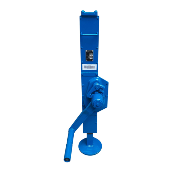
Brano 15-00 Operation Manual

Brano 15-00 Operation Manual

Rack jack

Advertisement

Quick Links

translation of the original instructions for use (also applies to special designs)
BRANO a.s., 747 41 Hradec nad Moravicí
the Czech Republic
tel.: +420/ 553 632 303
http://www.brano-zz.cz; http://www.brano.eu;
zz-info@brano.eu;
info@brano.eu
OPERATION MANUAL
SECURITY PRINCIPLES, OPERATION AND MAINTENANCE
FOR
RACK JACK
15-00
2,5t
5t
Type
load capacity
and
15-01
10t
16t
Type
load capacity
and
Z23
20t
Type
load capacity
DESIGN WITH RATCHET CRANK – RK
DESIGN WITH RATCHET HANDLE-LEVER – RKP
DESIGN WITH ADJUSTABLE SUPPORT – VK
DESIGNED IN EXPLOSIVE ENVIRONMENTS – NEXP
Peruse the operation manual before using the jack. It comprehends substantial
security instructions and instructions for use, installation and maintenance of the
product. Ensure the Operation Manual to be available for all responsible persons.
Keep for next usage!
Edition 8
JANUARY 2021
Registration number 1-52182-0-1

Advertisement

Table of Contents
loading

Summary of Contents for Brano 15-00

  • Page 1 (also applies to special designs) BRANO a.s., 747 41 Hradec nad Moravicí the Czech Republic tel.: +420/ 553 632 303 http://www.brano-zz.cz; http://www.brano.eu; zz-info@brano.eu; info@brano.eu OPERATION MANUAL SECURITY PRINCIPLES, OPERATION AND MAINTENANCE RACK JACK...
  • Page 2: Table Of Contents

    CONTENT 1 DEFINITION ......................3 2 DEVICE PURPOSE ....................3 3 SECURITY PRINCIPLES ..................4 3.1 SECURITY PRINCIPLES OVERVIEW ................4 3.2. SECURITY PRINCIPLES ....................4 3.2.1 Prior to use ........................4 3.2.2 When in use ......................... 5 3.2.3 After use ........................5 3.2.4 Risk analysis ........................
  • Page 3: Definition

    Operation Manual. 2 DEVICE PURPOSE 2.1 The rack jack type 15-00 load capacity 2,5t and 5t, 15-01 load capacity 10t and 16t, Z23 load capacity 20t in any combination of design (-RK, -RKP, -VK) and in design for potentially explosive atmospheres -NEXP (hereinafter referred to as...
  • Page 4: Security Principles

    3 SECURITY PRINCIPLES 3.1 SECURITY PRINCIPLES OVERVIEW A hazard exists when handling loads especially in the event that the jack is not use in the right way or is badly maintained. Whereas as a result an accident or severe injury could happen, it is necessary to observe the special security measures when handling, assembling, maintaining and checking the jack.
  • Page 5: When In Use

    3.2.2 When in use ALWAYS attend to the jack would stay vertically when jacking up. ALWAYS make sure that the foot of the comb bar rests on the ground with the entire contact surface. ALWAYS make sure the load is fitly put on the jack. ALWAYS pay increased attention, if the jack is drawn up to maximum position.
  • Page 6: Storage

    E.g. product parameters 15-01-NEXP/10t correspond to product parameters 15- 01/10t. Load Actuating capacity Main dimensions (mm) Weight force on Type-design (kg) crank 15-00 15-00-RK 15-00-VK 2,5 1,75 735 250 15-00-VK-RK 15-00-RKP 15-00-VK-RKP 15-00 15-00-RK 15-00-VK 765 300...
  • Page 7 Main dimensions design - VK Load Type-design capacity P (mm) R (mm) Fig.1 15-01-VK 15-01-VK 15-01-VK Main dimensions – all type Fig. 2 Main dimensions – design - RKP Fig. 3 Position transport Position lever Position crank Overloading safety...
  • Page 8: Mechanical Device

    5.1 MECHANICAL DEVICE Safety and working life of the jack is guaranteed if it works in accordance with specified classification. The jack is designed for class 1Bm according to the FEM 9.511 regulation – see table 5.1. (it corresponds to mechanism classification M3 according to the ISO 4301/1).
  • Page 9: Data On The Product

    5.2.4 The jack does not exceed the noise value specified in the Annex No.1 article 1.7.4.2 letter u of the ministerial order No. 176/2008 of the Collection of Law (EP and RE directive No. 2006/42/EC). Note: Articles 5.2.2 and 5.2.3 3 apply to NEXP product design. 5.3 DATA ON THE PRODUCT Each product is equipped with the label with specified data as follows: Standard finish:...
  • Page 10: Rest Adjustment

    6.2 REST ADJUSTMENT (only design - VK). Position of the adjustable rest can be changed in the range given by a number of mounting positions on the jack bar (see fig.1) After removal of the breaking piece (2) and shifting of Fig.
  • Page 11: Bearing Surface Check-Up /Floor, Rough Ground

    – see articles Fastening by the help of the opening in foot Fixace pomocí otvoru v patce 2.3, 2.4 and 5.3 of this OM. The lifters type 15-00 (load capacity 2,5 and 5t) have an opening in the foot which simplifies work...
  • Page 12: Safety Work Environment

    7.1.2 By reason that the work with heavy loads can constitute unexpected hazard it is necessary to follow all „Security principles“ according to the chapter 3 of this 7.2 SAFETY WORK ENVIRONMENT ! Warning (1) The operating personnel must be demonstrably acquainted with this Operation Manual;...
  • Page 13: Daily Inspection

    8.1.2 Daily inspection Check up at parts recommended in the section 8.2(1) „Daily inspection“, whether the jacks are not damaged nor have no defect. Carry out this inspection also during operation in the interval between regular inspections. Qualified employees will determine, whether any defect or damage can constitute a hazard and whether the detailed inspection is necessary.
  • Page 14: Trouble-Shooting

    (2) Regular inspection (carried out by the competent person) Limit / criteria for Inspection putting-out of Remedy Part method operation 1. Fixative parts Visual inspection Faulty or missing Replace by new of all screws, nuts, parts; ones; rivets etc. Released parts To retighten released parts 2.
  • Page 15: Greasing

    10 GREASING 10.1 GENERALLY Before application of the grease remove old grease, clean up components with grease solvent and apply new grease. Use grease specified by the producer. Lifters of load capacity 2,5, 5 a 10t are equipped with a lubrication plug on the cover of the gear transfer.
  • Page 16: Replacement Of Brake Inserts And Brake Adjusting

    11.2 REPLACEMENT OF BRAKE INSERTS AND BRAKE ADJUSTING 11.2.1 Brake disassembly (fig. 6) Demount the (crank or crank-lever) from the jack. Unbolt safety screws (6) and consequently the nut (5). Take out the spring (4) and crank arm (7). Take out from the hub (1) the ratchet (3) with brake insert (2A), take off the brake insert (2B), and replace both brake inserts (2A) (2B).
  • Page 17: Check Up

    11.5 CHECK UP Check up, whether all disassembled parts are suitable for next use. 1. Check up, whether no parts are worn out and have no chutes or fissures. 2. Check up, whether threaded parts have not the damaged thread. 11.6 REPAIR Outworn or damaged parts must be replaced.

Table of Contents