Table of Contents
Advertisement
Quick Links
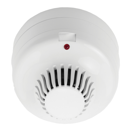
ZR432-2P Wireless Multisensor (Optical/Heat)
Detector Installation Sheet
Description
The ZR432-2P Wireless Multisensor (Optical/Heat) Detector is
specifically designed for use with the Ziton ZP1, ZP2 (all
versions) and ZP3 addressable control panels (firmware
versions 3.12 and later).
Note:
When used with legacy Ziton ZP3 (firmware version 3.11
and earlier) or ZP5 systems, the detector functions and
Installation methods may be different. These differences are
described in this installation sheet.
The detector incorporates a red LED for visual indication of the
alarm state and is designed for indoor use with the supplied
wireless mounting bases.
Table 1: Detectors (with wireless base included)
Model
Description
ZR432-2P
Wireless Multisensor (Optical/Heat)
Detector and base, Polar White
ZR432-2PA
Wireless Multisensor (Optical/Heat)
Detector and base with Sounder, Polar White
ZR432-2PAV
Wireless Multisensor (Optical/Heat)
Detector and base with Sounder and Visual
Indicator, Polar White
Table 2: Replacement parts
Model
Description
ZX432-2P [1]
Multisensor (Optical/Heat) Detector, Polar White
ZR401-3P
Ziton Protocol 868 MHz, Radio Sensor Base for
ZX432-2P with battery pack, Polar white
ZR401-3PA
Ziton Protocol 868 MHz, Radio Sensor Sounder
Base for ZX432-2P with battery pack, Polar white
ZR401-3PAV
Ziton Protocol 868 MHz, Radio Sensor Sounder
Base with Visual Indicator for ZX432-2P with
battery pack, Polar white
[1] Supplied without the wireless base.
© 2018 UTC Fire & Security. All rights reserved.
Operation
868 MHz systems
Subject to configuration, the detector can operate as a
multisensor, a smoke detector, or a heat detector. For detector
configuration details, see Configuration: 868 MHz systems.
Legacy systems
Subject to configuration and the detector base used, the
detector can operate as a multisensor, a smoke detector, or a
heat detector, as shown below.
Operation
Smoke detector
Heat detector
For detector configuration details, see Configuration: Legacy
systems.
Configuration: General
Configure the device using the seven-segment DIP switch
(SW1) on the back of the detector.
Figure 1: DIP switch SW1
1.
Sensitivity 1
2.
Sensitivity 2
3.
Heat band select
4.
Head type (selection 1)
5.
Head type (selection 2)
6.
Not used
7.
Base compatible
1 / 4
Mounting base
ZR401-1, ZR401-MS-2
ZR401-1, ZR401-MS-2
P/N 10-4213-501-ZX01-02 • ISS 12MAR18
Advertisement
Table of Contents

Related Manuals for Ziton ZR432-2P


Summary of Contents for Ziton ZR432-2P
- Page 1 Heat detector ZR401-1, ZR401-MS-2 The ZR432-2P Wireless Multisensor (Optical/Heat) Detector is For detector configuration details, see Configuration: Legacy specifically designed for use with the Ziton ZP1, ZP2 (all systems. versions) and ZP3 addressable control panels (firmware versions 3.12 and later).
- Page 2 Configuration: 868 MHz systems Configuration: Legacy systems Dual detector mode Dual detector mode To operate the device in dual detector mode, DIP switch 7 To operate the device in dual detector mode, it must be used (SW1) must be set to OFF (see Figure 1), enabling the with the ZR401-MS-2 Multisensor Radio Base and DIP detector to make the alarm decision based on both the switch 7 (SW1) must be set to OFF (see Figure 1), enabling...
- Page 3 Table 5: DIP switch SW1 settings for single detector mode with ZR401-3 and ZR401-MS-2 bases [1] Mode Optical only Heat only [1] This configuration complies with EN 54-7 and EN 54-5 standards (class A1). Table 6: DIP switch SW1 settings for single detector mode with a ZR401-1 mounting base Mode ZR430 Optical compatibility ZR420 Heat compatibility...
- Page 4 ZR401-MS-2-SWE municipal waste in the European Union. For proper recycling, return this product Compatibility Ziton ZP1, ZP2 and ZP3 systems to your local supplier upon the purchase (firmware versions 3.12 and later) of equivalent new equipment, or via ZPR868 loop module...
Need help?
Do you have a question about the ZR432-2P and is the answer not in the manual?
Questions and answers