Table of Contents
Advertisement
Quick Links
Advertisement
Table of Contents

Related Manuals for GREEN INSTRUMENTS G3600


Summary of Contents for GREEN INSTRUMENTS G3600
- Page 1 G3600/3601 Inert Gas Sampling Boards Manual...
-
Page 3: Table Of Contents
Inert Gas Sampling Boards 3600 3601 Content ....................5 NTRODUCTION ......................5 BOUT THIS ANUAL ....................6 NQUIRIES AND EEDBACK ....................7 PECIFICATIONS ....................8 NSTALLATION ...................... 8 ONTROL AT ELIVERY ..................8 HERE TO NSTALL THE YSTEM ......................8 AFETY SPECTS ......................... - Page 4 Content ABLE OF IGURES 3-1: P ......10 IGURE IPING AND INSTRUMENTATION DIAGRAM SINGLE SAMPLING BOARD – 3-2: IGOA ..............11 IGURE SYSTEM SINGLE SAMPLING BOARD 3-3: IGOA S ..............13 IGURE YSTEM DOUBLE SAMPLING BOARD – 3-4: P ......14 IGURE IPING AND INSTRUMENTATION DIAGRAM DOUBLE SAMPLING BOARD...
-
Page 5: Introduction
The instructions have been made in general terms and do not take into con- sideration the existing equipment of the inert gas system and its installation. As such, the manual is designed for the standard Green Instruments IGOA System. Virtu- ally all systems are fitted with a G Oxygen Analyzer. -
Page 6: Inquiries And Feedback
Green Instruments A/S reserves the copyright of this manual. Without prior written per- mission of Green Instruments A/S, the manual may not be copied and given to unauthor- ized people. -
Page 7: Specifications
Inert Gas Sampling Boards 3600 3601 2 Specifications Sampling Board for Inert Gas Application 0.05 to 1 bar – 2 to 8 l/min Sample inlet pressure & flow Sample inlet temperature 0°C to 70°C 3 ports – 1/8” BSP connection Sample manifold Max. -
Page 8: Installation
Installation and operation Installation and operation of the sampling board and associated equipment must be car- ried out by skilled personnel, and that Green Instruments does not take any responsibility of the operation of the system and associated equipment whatsoever. -
Page 9: Single Board
Inert Gas Sampling Boards 3600 3601 The successful and safe operation of this equipment is dependent upon proper handling, installation, operation, and maintenance. Recycling Do not dispose any part of the sampling system with regular waste. Disposal should be in accordance with the requirements of the current statutory regulations. -
Page 10: Calibration Gas Connection
Installation GI supply Valve 00358 Sample 3 – 1/8" BSP Sample 2 – 1/8" BSP Sample 1 – 1/8" BSP Ventilation - 1/8" BSP Sensor 00390 GI supply Valve 01475 GI supply Zero Calib. Gas D.Flow 1/8" BSP Switch (optional) 01453 Filter of Regulator... -
Page 11: Figure 3-2: Igoa System - Single Sampling Board
Inert Gas Sampling Boards 3600 3601 Figure 3-2: IGOA system – single sampling board Ver.2.3 – Revision April 2022... -
Page 12: Vent Line Connection
Installation 3.4.4 Vent Line Connection The vent line connection for the bubble glass is placed right below the sample ports. It is for the connection of an external vent line which allows venting the sampled inert gas from the bubble glass to the outside air. The vent line must be dimensioned to allow a gas flow of at least 10 l/min and arranged in such a way that it avoids backpressure and se- cures a sufficient sample gas flow (i.e. -
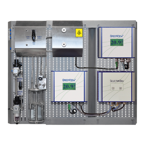
Page 13: Figure 3-3: Igoa System - Double Sampling Board
Inert Gas Sampling Boards 3600 3601 Figure 3-3: IGOA System - double sampling board Ver.2.3 – Revision April 2022... -
Page 14: Figure 3-4: Piping And Instrumentation Diagram - Double Sampling Board
Installation GI supply Valve 00358 Sample 3 – 1/8" BSP Sample 2 – 1/8" BSP Sensor 2 Sample 1 – 1/8" BSP 00390 Ventilation – 1/8" BSP Valve Oxygen Analyzer 2 01477 (specification in a GI supply separate manual) Sensor 1 00390 Sensor Cable... -
Page 15: Figure 3-5: Electrical Connections Of The Selector Box G3505
Inert Gas Sampling Boards 3600 3601 Power Supply Protective earth Spade Mains IN Neutral Live J3 - Terminal 1 Power lead J3 - Terminal 2 Power Unit 1 - prewired Neutral Live J2 - Terminal 1 Power lead J2 - Terminal 2 Power Unit 2 - prewired Neutral Live J4 - Terminal 1... -
Page 16: Figure 3-6: Electrical Connections Of The Selector Box G36
Installation Power Supply – Main In Power Lead J11-L Neutral Live J11-N Protective earth Power Supply – Unit 1 (A) Power Lead J9-L Neutral Live J9-N Protective earth Power Supply – Unit 2 (B) Power Lead J10-L Neutral Live J10-N Protective earth Relay Output –... -
Page 17: Retrofitting Of Extension Board
Inert Gas Sampling Boards 3600 3601 3.6 Retrofitting of Extension Board The G Extension Board including a G36 Oxygen Analyzer and a selector box Type 3609 G36 can be retrofitted to an existing single sampling board (G or G ). This makes 3600 3602 the single board function like a double board. - Page 18 Installation Standby Redundancy – selector box DIP The system can be configured that both analyzers are powered ON at the same time or only one of them is powered ON. The setting is at DIP switches at the selector box G36. Power Supply DIP Switches Unit 1 or Unit 2 powered ON...
-
Page 19: Commissioning
Inert Gas Sampling Boards 3600 3601 4 Commissioning Before starting the system for the first time after completing the installation, please check the installation of the system. 4.1 Installation Checks of the Sampling Board • Check that the span and zero calibration gases are connected, and that all connec- tions are secured and not leaking. - Page 20 Commissioning er, too high velocity – indicated by an enormous number of bubbles, will change the sen- sor temperature and consequently the readings. • Turn the selector valve to Test Gas and the calibration selector valve to Zero Gas and adjust the zero gas reduction station until the flow is about the same as noted for the sample gas by observing the bubble flow.
-
Page 21: Routine Maintenance
Inert Gas Sampling Boards 3600 3601 5 Routine Maintenance 5.1 Sampling System Routine inspection and maintenance of the sampling system is required to make sure no gas is leaking from the test or calibration gas supply. Failure to periodically inspect and maintain the above requirements may lead to imprecise analyzer readings and thus a mal- function of the inert gas system. -
Page 22: Analyzer
Routine Maintenance tral detergent. O-rings for the bubble glass may require replacement for leak free opera- tion. Prevent the glass from ultraviolet rays and adhesion of organic solvents. For spare parts, see the list of spare parts in chapter 6. Please also check that the vent line functions uninterrupted and secures a sufficient gas flow. -
Page 23: Spare Parts
Inert Gas Sampling Boards 3600 3601 6 Spare Parts Spare parts are not included in the standard delivery. Spare parts can be ordered when necessary. When ordering spare parts, please mention the serial number of the analyzer, which you can find on the label on the right side of the blue analyzer box. the specific appearance of the spare parts is Part Part Description... - Page 24 Spare Parts the specific appearance of the spare parts is Part Part Description subject change without notice; the function however will not change Zero gas regulator – 1/8”, 0.02–2 bar 00659 00477 Sensor cable complete 0.8 m 01121 Sensor cable complete 1.5 m 00922 Sensor cable complete 3.0 m 00605...
- Page 25 Inert Gas Sampling Boards 3600 3601 the specific appearance of the spare parts is Part Part Description subject change without notice; the function however will not change 01475 Bubble glass complete 01477 Needle consol valve for bubble glass 01241 Oxygen Analyzer 100-230 VAC 01245 Oxygen Analyzer manual Includes 1 x 00328, 2 x 00373, 1 x...
- Page 26 Spare Parts the specific appearance of the spare parts is Part Part Description subject change without notice; the function however will not change 01453 Digital flow switch 0.2-10 l/min (optional) 33594 Pre-Filter incl. filter cartridge 00980 Filter cartridge for pre-filter Other optional equipment can be supplied e.g.: Flow alarm, visualization, recording and data logging, monitoring of inert gas temperature, pres- sure, and load, remote digital display, signal amplifier for logarithmic output.
- Page 28 EUROPE Green Instruments A/S Erhvervsparken 29 9700 Brønderslev, Denmark Tel: +45 96 45 45 00 sales@greeninstruments.com AMERICA Green Instruments USA, Inc. 6750 N. Andrews Avenue Suit 200 Fort Lauderdale, FL-33309, USA Tel: +1 954 613 0400 usa@greeninstruments.com ASIA Green Instruments (S) Pte. Ltd. 4008 Ang Mo Kio Avenue 10 #01-09/10 Techplace I, Singapore 569625 Tel: +65 3100 0577 sales.sg@greeninstruments.com...
Need help?
Do you have a question about the G3600 and is the answer not in the manual?
Questions and answers