Table of Contents
Advertisement
Quick Links
Advertisement
Table of Contents

Subscribe to Our Youtube Channel
Related Manuals for GREEN INSTRUMENTS G3620A


Summary of Contents for GREEN INSTRUMENTS G3620A
-
Page 1: G 3620 A / P Stack Gas Oxygen Analyzing System
G3620A/P STACK GAS OXYGEN ANALYZING SYSTEM PART NUMBER.: 01760... -
Page 3: Table Of Contents
G3620a/p Stack Gas Oxygen Analyzing System Contents TACK XYGEN NALYZING YSTEM 3620 NTRODUCTION BOUT THIS ANUAL NQUIRIES AND EEDBACK BOUT THE YSTEM PECIFICATIONS NSTALLATION ONTROL AT ELIVERY HERE TO NSTALL THE YSTEM AFETY SPECTS JECTOR ROBE NALYZING OARD 3.5.1 Air supply connection 3.5.2... -
Page 4: Introduction
1 Introduction 1.1 About this Manual The G3620a/p Stack Gas Oxygen Analyzing System, hereafter named a SGOA System, consists of an oxygen analyzer, a sampling board, and a probe. This manual contains data and instructions for the installation, operation, and mainte- nance of the sampling board and the SGOA System as a whole. -
Page 5: Inquiries And Feedback
Green Instruments A/S reserves the copyright of the manual. Without prior written per- mission of Green Instruments A/S, the manual may not be copied and given to unauthor- ized people. -
Page 6: About The System
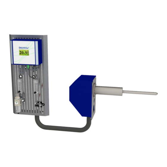
Introduction 1.3 About the System The G3620a/p SGOA System is designed to measure the content of oxygen in stack gas. The compact design provides a wide range of configuration possibilities, outstanding per- formance, reliable and in-situ real-time monitoring. The system consists of the following main elements: Ejector probe complete with filter, sampling tube, sensor, and housing. -
Page 7: Specifications
G3620a/p Stack Gas Oxygen Analyzing System 2 Specifications Gas Connection Max. 1 bar – quick coupling for 6 mm OD hose Test gas inlet Max. 10 bar – 1/8” BSP connection Air supply inlet Air supply quality Instrument air according to ISO 8573-1 Class 3.3.3... -
Page 8: Installation
Read this chapter in its entirety before installing the system. 3.1 Control at Delivery When you receive the G3620a/p SGOA System, please inspect and confirm that the re- ceived scope of supply is in accordance with the packing list and not damaged. -
Page 9: Figure 3-1: Installation Layout Of The G3620A With G36A Stand-Alone Analyzer
Stack Gas O2 Analyzing System Yard Supply 3620a 1pc Probe with Sensor connected with a 3.0 m long umbilical cord to 1pc Sampling Control Board including G Oxygen Analyzer Signal Cable Yard Supply Figure 3-1: Installation layout of the G3620a with G36a stand-alone analyzer... -
Page 10: Figure 3-2: Installation Layout Of The G3620P With G36P Panel Mounted Analyzer
Installation Exhaust Duct Yard Supply Maintenance space: 700 mm Distance to the outlet: min. 3 duct diamters Distance to the next downstream bent: 600 × 285 × 180 mm min. 1 duct diameters On-Stack Probe 600 mm Signal Cable standard 3 m & max. 6 m Sample to be drawn from the Length/min. -
Page 11: Safety Aspects
Installation and operation! The installation and operation of the G3620a/p SGOA System and associated equipment must be carried out by skilled, trained, and certified personnel. Green Instruments A/S does not take any responsibility for the operation of the system and associated equipment whatsoever. -
Page 12: Figure 3-3: O 2 Ejector Probe Standard
Installation Figure 3-3: O ejector probe standard Figure 3-4: O ejector probe short... -
Page 13: Analyzing Board
G3620a/p Stack Gas Oxygen Analyzing System 3.5 Analyzing Board The analyzing board is designed for mounting with the G Oxygen Analyzer or the G Oxygen Analyzer for panel mounting. For the G3620p, the analyzing board is connected to the panel mounted analyzer by a standard 3 m long signal cable. This signal cable can be delivered up to 6m as optional. -
Page 14: Figure 3-5: Analyzing Board With G 36 A Oxygen Analyzer Mounted On Board
Installation Figure 3-5: Analyzing board with G Oxygen Analyzer mounted on board... -
Page 15: Figure 3-6: Piping And Connection Diagram Of The G3620A
GI Supply GI Supply Instrument air Test gas Max. 10 bar. Max. 1 bar Conn. Female1/8" Conn. OD 6 mm GI Supply GI Supply Board dimensions: 600 × 290 × 138 mm Figure 3-6: Piping and connection diagram of the G3620a... -
Page 16: Figure 3-7: Analyzing Board With Connector Box For G 36 P Oxygen Analyzer
Installation Figure 3-7: Analyzing board with connector box for G Oxygen Analyzer... -
Page 17: Figure 3-8: Piping And Connection Diagram Of The G3620P
G3620a/p Stack Gas Oxygen Analyzing System Connection Panel mounted analyzer GI Supply GI Supply Instrument air Test gas Max. 10 bar. Max. 1 bar Conn. Female1/8" Conn. OD 6 mm GI Supply GI Supply Board dimensions: 600 × 290 × 138 mm... -
Page 18: Commissioning
Commissioning 4 Commissioning 4.1 Installation and Setup Pre-checks After completing the installation and before starting the system for the first time, please check the following: Check and confirm that all electrical connections are carried out according to the manual. Check that the air supply is connected to the air supply filter regulator without leaking and in accordance with good installation practice. -
Page 19: Routine Maintenance
G3620a/p Stack Gas Oxygen Analyzing System 5 Routine Maintenance Warning The sensor/probe is hot and can cause severe burning of personnel if not handle with care. Turnoff the analyzer before working with the probe and sensor. Before removing the probe from the stack, make sure that there is no over-pressure or hot exhaust gas inside the stack. -
Page 20: Sensor
Routine Maintenance keep the filter clean. However, slow responds to O changes in the flue gases indicates that the probe filter or the probe venturi air nozzle is contaminated. In case of heavy filter contamination, manual cleaning of the filter and the probe venturi air nozzle will be re- quired. -
Page 21: Spare Parts
G3620a/p Stack Gas Oxygen Analyzing System 6 Spare Parts The specific appearance of the spare parts is subject Part Part Description change without notice; the function however will not change Air supply filter regulator 00657 1/8”, 0-2 bar Flange Gasket OD 100 for Stack... - Page 22 Spare Parts The specific appearance of the spare parts is subject Part Part Description change without notice; the function however will not change 01243 G36a Oxygen Analyzer 100-230 VAC 01245 G36 Oxygen Analyzer manual 01251 Fuse 2 AT (pkg of 10) SEN9 Oxygen sensor screw-in type 01258 –...
- Page 23 G3620a/p Stack Gas Oxygen Analyzing System The specific appearance of the spare parts is subject Part Part Description change without notice; the function however will not change G36p Oxygen Analyzer 24 VAC (in- 02190 cluding 01388) 01388 Gasket for panel mounted analyzer...
- Page 24 Green Instruments A/S Green Instruments USA, Inc. Green Instruments (S) Pte. Ltd. sales@greeninstruments.com usa@greeninstruments.com sales.sg@greeninstruments.com Erhvervsparken 29 6750 N. Andrews Avenue Suite 200 4008 Ang Mo Kio Avenue 10 9700 Brønderslev, Denmark...
Need help?
Do you have a question about the G3620A and is the answer not in the manual?
Questions and answers