
Subscribe to Our Youtube Channel
Related Manuals for GREEN INSTRUMENTS G3621A/P


Summary of Contents for GREEN INSTRUMENTS G3621A/P
- Page 1 G3621A/P STACK GAS OXYGEN ANALYZING SYSTEM WITH DIFFUSION PROBE PART NUMBER.: 02155...
- Page 2 Version 2.2 – Oct 2020...
-
Page 3: Table Of Contents
G3621a/p Stack Gas Oxygen Analyzing System Content TACK XYGEN NALYZING YSTEM WITH IFFUSION ROBE 3621 NTRODUCTION BOUT THIS ANUAL NQUIRIES AND EEDBACK BOUT THE YSTEM PECIFICATIONS AFETY SPECTS ONTROL AT ELIVERY NSTALLATION HERE TO NSTALL THE YSTEM IFFUSION ROBE NALYZING OARD 5.3.1... -
Page 4: Introduction
1 Introduction 1.1 About this Manual The G3621a/p Stack Gas Oxygen Analyzing System, hereafter named an SGOA System, consists of an oxygen analyzer, an analyzing board, and a diffusion probe. This manual contains data and instructions for the installation, operation, and mainte- nance of the analyzing board and the SGOA System as a whole. -
Page 5: Inquiries And Feedback
Green Instruments A/S reserves the copyright of the manual. Without prior written per- mission of Green Instruments A/S, the manual may not be copied and given to unauthor- ized people. -
Page 6: About The System
Introduction 1.3 About the System The G3621a/p SGOA System is designed to measure the content of oxygen in stack gas. The compact design provides a wide range of configuration possibilities, outstanding per- formance, reliable and in situ real-time monitoring. The system consists of the following main elements: Diffusion probe complete with filter, gas tube, sensor, and housing. -
Page 7: G 3621 A / P Stack Gas Oxygen
G3621a/p Stack Gas Oxygen Analyzing System 2 Specifications Gas Connection Max. 1 bar – quick coupling for 6 mm OD hose Test Gas Inlet Max. 10 bar – 1/8” BSP connection Air Supply Inlet Air Supply Quality Instrument air according to ISO 8573-1 Class 3.3.3... -
Page 8: Safety Aspects
The installation and operation of the G3621a/p SGOA System and associated equipment must be carried out by skilled personnel. Green Instruments A/S does not take any responsibility for the operation of the system and associated equipment whatsoever. The successful and safe operation of this equip- ment is dependent on proper handling, installation, operation, and maintenance. -
Page 9: Control At Delivery
G3621a/p Stack Gas Oxygen Analyzing System 4 Control at Delivery When you receive the G3621a/p SGOA System, please inspect and confirm that the re- ceived scope of supply is in accordance with the packing list and not damaged. Any discrepancy should be reported to the supplier immediately. If any of the received parts are damaged, the shipping company should be informed, and new parts should be made available before completing the installation. -
Page 10: Installation
It is recommended to place the diffusion probe as illustrated in Figure 5-1 and Figure 5-2 below. If you find it difficult estimating where to install the diffusion probe, please contact Green Instruments A/S for more instructions. Version 2.2 – Oct 2020... - Page 11 G3621a/p Stack Gas Oxygen Analyzing System Exhaust Duct Yard Supply Maintenance space: 700 mm Distance to the outlet: min. 3 duct diamters Distance to the next downstream bent: 600 × 285 × 180 mm min. 1 duct diameters On-Stack Probe...
- Page 12 Installation Exhaust Duct Yard Supply Maintenance space: 700 mm Socket: Yard supply to be welded Distance to the outlet: min. 3 duct diamters Thread size: 1½” BSP Distance to the next downstream bent: min. 1 duct diameters On-Stack Probe 600 × 285 × 180 mm 600 mm Signal Cable standard 3 m &...
- Page 13 G3621a/p Stack Gas Oxygen Analyzing System 5.2 Diffusion Probe The sample gas flow is diffused through the sample filter element into the sensor area. The gas, which passes the probe, must represent the gas to be tested and extracted from a location with laminar flow.
- Page 14 Installation Figure 5-4: Diffusion Probe Short – Welding Type Figure 5-5: Diffusion Probe Standard – Thread Type Version 2.2 – Oct 2020...
-
Page 15: Analyzing Board
G3621a/p Stack Gas Oxygen Analyzing System Figure 5-6: Diffusion Probe Short – Thread Type 5.3 Analyzing Board 5.3.1 Mounting Board The analyzing board is designed for mounting with the G36a Oxygen Analyzer (see Figure 5-7 andFigure 5-8) or the G36p Oxygen Analyzer for panel mounting (see Figure 5-9 and). - Page 16 Installation 5.3.3 Test Gas Connection For system verification, test gas is connected to the inlet valve. The connection is a quick coupling for OD 6/4 mm hose. The maximum pressure for the test gas inlet is 1 bar. 5.3.4 Analyzer and Electrical Connection For the SGOA system installation, the instructions for the electrical connections are described in the oxygen analyzer manual chapter 3.
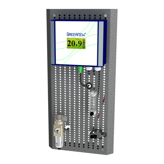
- Page 17 G3621a/p Stack Gas Oxygen Analyzing System Figure 5-7: Analyzing Board with G36a Oxygen Analyzer Mounted on Board...
- Page 18 Installation Analyzer 01243 220V/110V Power supply See rating Cable dia. 11-14 mm Signal output 4-20 mA Cable dia. 11-14 mm GI Supply Instrument air Test gas GI Supply Max. 10 bar. Max. 1 bar Conn. OD 6 mm Conn. Female1/8" GI Supply GI Supply Figure 5-8: Piping and Connection Diagram of the G3621a...
- Page 19 G3621a/p Stack Gas Oxygen Analyzing System Figure 5-9: Analyzing Board with Connector Box for G Oxygen Analyzer...
- Page 20 Installation Connection Panel mounted analyzer Instrument air Test gas GI Supply GI Supply Max. 10 bar. Max. 1 bar Conn. Female1/8" Conn. OD 6 mm GI Supply GI Supply Figure 5-10: Piping and Connection Diagram of the G3621p Version 2.2 – Oct 2020...
-
Page 21: Commissioning
G3621a/p Stack Gas Oxygen Analyzing System 6 Commissioning 6.1 Installation and Setup Pre-checks After completing the installation and before starting the system for the first time, please check the following: Check and confirm that all electrical connections are carried out according to the manual. -
Page 22: Routine Maintenance
Routine Maintenance 7 Routine Maintenance Warning The sensor/probe is hot and can cause severe burning of personnel if not handle with care. Turnoff the analyzer before working with the probe and sensor. Before removing the probe from the stack, make sure that there is no over-pressure or hot exhaust gas inside the stack. -
Page 23: Diffusion Probe
G3621a/p Stack Gas Oxygen Analyzing System 7.3 Diffusion Probe The probe filter is normally cleaned by automatic backflushing. The period between backflushing’s is determined by the setup and should be set and changed according to the actual flue gas condition and how dirty the filter gets. Regular backflushing will normally keep the filter clean. - Page 24 Routine Maintenance Turn off the analyzer and remove the blue cover plate of the probe. Unplug the sensor connection. Loose the sensor from the probe head by using a spanner and pull out the sensor. Screw a new sensor into the probe and set the sensor plug to the sensor connector. Then close the cover plate.
-
Page 25: Spare Parts
G3621a/p Stack Gas Oxygen Analyzing System 8 Spare Parts Spare parts are not included in the standard delivery. Spare parts can be ordered when necessary. When ordering spare parts, please mention the serial number of the analyzer, which you can find on the label on the right side of the blue analyzer box. - Page 26 Spare Parts Part The specific appearance of the spare parts is subject Part Description change without notice; the function however will not change G36a Oxygen Analyzer 100-230 01243 01245 G36 Oxygen Analyzer manual 01251 Fuse 2 AT (pkg of 10) SEN9 Oxygen sensor screw-in type 01258 –...
- Page 27 G3621a/p Stack Gas Oxygen Analyzing System Part The specific appearance of the spare parts is subject Part Description change without notice; the function however will not change 01398 Valve for test gas SD card with Green Instruments’ software & standard settings files -...
- Page 28 Green Instruments A/S Green Instruments USA, Inc. Green Instruments (S) Pte. Ltd. sales@greeninstruments.com usa@greeninstruments.com sales.sg@greeninstruments.com Erhvervsparken 29 6750 N. Andrews Avenue Suite 200 4008 Ang Mo Kio Avenue 10 9700 Brønderslev, Denmark...
Need help?
Do you have a question about the G3621A/P and is the answer not in the manual?
Questions and answers