Table of Contents
Advertisement
Quick Links
INSTRUCTION MANUAL
Real Time Video Recorder
Magnétoscope à en temps réel
Videograbador en tiempo real
Please read this manual and accompanying "IMPORTANT SAFETY INSTRUCTIONS" sheet carefully before connecting your
VCR and operating it for the first time.
Be sure to read carefully and follow all the PRECAUTIONS on page 1 and 2.
Keep the manual in a safe place for future reference.
SRT-2400
English
Français
Español
Advertisement
Table of Contents

Related Manuals for Sanyo SRT-2400


Summary of Contents for Sanyo SRT-2400
- Page 1 Videograbador en tiempo real Please read this manual and accompanying “IMPORTANT SAFETY INSTRUCTIONS” sheet carefully before connecting your VCR and operating it for the first time. Be sure to read carefully and follow all the PRECAUTIONS on page 1 and 2.
-
Page 2: Precautions
PRECAUTIONS CAUTION RISK OF ELECTRIC SHOCK DO NOT OPEN CAUTION: TO REDUCE THE RISK OF ELECTRIC SHOCK, DO NOT REMOVE COVER (OR BACK). NO USER-SERVICEABLE PARTS INSIDE. REFER SERVICING TO QUALIFIED SERVICE PERSONNEL. WARNING: To reduce the risk of fire or electric shock, do not expose this appliance to rain or other moisture. - Page 3 Avoid locations subject to strong vibrations. Avoid moving the VCR between cold and hot locations (see “Moisture Condensation Problems”, this page). Do not place the VCR directly on top of the TV, as this may cause playback or recording problems. Avoiding Electrical Shock and Fire Do not handle the power cord with wet hands.
-
Page 4: Table Of Contents
Alarm search and Alarm scan function Forward/Reverse field advance function 30-day memory backup Security lock Recording check function Automatic head cleaning function When using the optional RS-485 board, the VCR can be controlled from a special controller. ACCESSORY Power cord... -
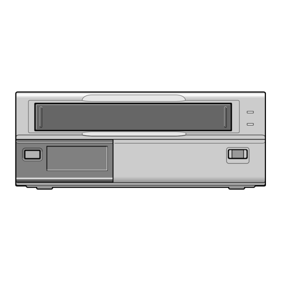
Page 5: Locations Of Controls And Indicators
LOCATIONS OF CONTROLS AND INDICATORS Front Panel EJECT EJECT button Cassette loading slot PAUSE/SEARCH button REW (rewind) button PLAY (REC CHECK) button FF (fast forward) button STOP button REC (record) button POWER indicator REPEAT (autorepeat recording) indicator 4 5 6 7 89F PAUSE/ PLAY... -
Page 6: Digital Display
Forward field advance Reverse field advance Clog detection indicator Flashes when the recording quality deteriorates due to dirty VCR heads. OFF indicator Comes on when the tape end has been reached after a recording, except during autorepeat recording mode. Cassette indicator Comes on when a cassette is loaded. -
Page 7: Back Panel
LOCATIONS OF CONTROLS AND INDICATORS Back Panel ALARM OUT/ CLOCK OUT WARNING AC IN ~ PUSH OPEN REMOTE Battery compartment ALARM OUT/CLOCK OUT (alarm output/external clock set trigger output) terminal ALARM IN/CLCOK IN (alarm input/ external clock set trigger input) terminal COM (common) terminal SERIES OUT/NON REC OUT (series recording trigger output/non recording output) terminal... - Page 8 LOCATIONS OF CONTROLS AND INDICATORS Back Panel (With the optional RS-485 board) Battery compartment ALARM OUT/CLOCK OUT (alarm output/external clock set trigger output) terminal ALARM IN/CLCOK IN (alarm input/ external clock set trigger input) terminal COM (common) terminal SERIES OUT/NON REC OUT (series recording trigger output/non recording output) terminal SERIES IN (series recording trigger input) terminal SW OUT (switch output) terminal...
-
Page 9: Connections
You can use a VA-RMN01 Remote Control Unit (sold separately) to control remotely the VCR. The grounded power cord (3 pin plug) must be connected to a grounded power outlet. -
Page 10: On-Screen Menus
ON-SCREEN MENUS When no menu is displayed on-screen, press the MENU button. The (SET UP 1) menu appears. ° Press the MENU button to save any setting ° made and switch menu screens. NOTES: If the (POWER FAILURE)/(DEW)/(USED TIME) menu is displayed, pressing the MENU button will return to the monitor screen display. - Page 11 ON-SCREEN MENUS TAPE MANAGEMENT menu @@@@<TAPE@MANAGEMENT> *TAPE@MANAGE.@@@@N *PROTECT@DAY@@@@@30 *REC@PASS@SET@@@@10 *GROUP@NO.@@@@@@@OFF *OVERRIDE@@@@@@@@N TIMER SET menu @@@@@@<TIMER@SET> WEEK@START@@STOP@@@SPD SUN@@--:--@@--:--@@---@N MON@@--:--@@--:--@@---@N TUE@@--:--@@--:--@@---@N WED@@--:--@@--:--@@---@N THU@@--:--@@--:--@@---@N FRI@@--:--@@--:--@@---@N SAT@@--:--@@--:--@@---@N DLY@@--:--@@--:--@@---@N HOLIDAY SET menu @@@@@<HOLIDAY@SET> @@1@@-----@@@11@@----- @@2@@-----@@@12@@----- @@3@@-----@@@13@@----- @@4@@-----@@@14@@----- @@5@@-----@@@15@@----- @@6@@-----@@@16@@----- @@7@@-----@@@17@@----- @@8@@-----@@@18@@----- @@9@@-----@@@19@@----- @10@@-----@@@20@@----- ALARM TIME menu @@@@@@<ALARM@TIME>...
-
Page 12: Setting The Language And Clock
SETTING THE LANGUAGE AND CLOCK Language Setting English, French or Spanish can be selected by the user. Turn the power on to all devices used. Press the MENU button to display the (SET UP 1) menu. @@@@@@@<SET@UP@1> *LANGUAGE-LANGUE-IDIOMA @@@ENGLISH *CLOCK@SET @01-01-2000@SAT@00:00:00 *DAYLIGHT@SET@@@@@NO@USE @@@@@@@@WEEK@MONTH@TIME... - Page 13 SETTING THE LANGUAGE AND CLOCK Automatic Daylight Saving Time Adjustment Press the MENU button to display the (SET UP 1) menu. @@@@@@@<SET@UP@1> *LANGUAGE-LANGUE-IDIOMA @@@ENGLISH *CLOCK@SET @10-15-2001@MON@15:20:00 *DAYLIGHT@SET@@@@@NO@USE @@@@@@@@WEEK@MONTH@TIME @ON@@@1ST-SUN@@04@02:00 @OFF@@LST-SUN@@10@02:00 Press the ] button, until the “DAYLIGHT SET” setting is flashing. Press the l (or j) button to set the auto daylight saving time/standard time adjustment.
-
Page 14: Changing The On-Screen Display
“N” was set at step 4 above are not recorded. English Changing the Date/Time Display Position Turn the power on to all input devices to the VCR. Set the ON SCREEN switch to the “ON” position. ° The date and time are displayed. -
Page 15: Video Cassette Tapes
VIDEO CASSETTE TAPES Use only video cassette tapes bearing the w logo. This VCR was primarily designed for use with T-120 or T-160 cassette tapes, it is recommended to use T-120 or T-160 standard grade VHS video cassette tapes for optimal performance. - Page 16 Setting the Action to Take When a Cassette is Loaded In the (SET UP 3) menu, you can set the mode the VCR will go into when a cassette is loaded. Press the MENU button until the (SET UP 3) menu is displayed.
-
Page 17: Tape Management Function
Before using this function, make sure that the clock is set properly. Operation When recording is started, the VCR will rewind the tape to the beginning, and will playback some of the tape to check for the presence of tape management data (no image is displayed). -
Page 18: Setting The Tape Management Function
(alarm recordings, program timer recordings, holiday settings). When setting a program timer recording, the tape protection term is checked when the VCR is set to program timer recording stand-by mode. When a program timer recording is done, the data is updated when recording starts. - Page 19 (TAPE MANAGEMENT) menu is displayed with the conflicting setting flashing and the VCR go into the stop mode. If in the (SET UP 2) menu, in the BUZZER section WARNING is set to “Y”, the buzzer is heard. (To stop the buzzer, press the STOP button.)
-
Page 20: Normal Recording
EJECT, FF, REW or PLAY button. To stop recording, press the STOP button. NOTES: A tape recording made on this VCR may not play back with the same degree of clarity on a real time video recorder from another manufacturer. - Page 21 NOTES: The image appears on-screen but it is not recorded. If a recording pause continues for 5 minutes or more, the VCR will go into stop mode to avoid damaging the tape. tape) To resume recording, press the REC button, or press the PAUSE/SEARCH button again.
- Page 22 NORMAL RECORDING Changes to the Recording Speed Mode During Recording It is possible to permit or prevent changing the recording speed mode during recording. Press the MENU button until the (SET UP 4) menu is displayed. @@@@@@@<SET@UP@4> *SW@OUT @@TIMING@@@@@@@@@@FIELD @@FIELD@@@@@@@@@@@01 @@8H@@@@@@@@@@@@@@Y *THREAD@CHECK@@@@@Y *VIDEO@LOSS@@@@@@@N...
-
Page 23: Setting The Mode At The End Of The Tape
Setting the Mode at the End of the Tape In the (SET UP 3) menu, you can set the mode of the VCR mode when the tape reaches the end during recording. Press the MENU button until the (SET UP 3) menu is displayed. -
Page 24: Autorepeat Recording
Press the REC button. ° Recording will start. When the tape end is reached, the VCR will rewind it to the beginning, and recording will resume. When the end of the tape is reached, a buzzer °... -
Page 25: Alarm Recording
Y3..Alarm recording is done only if there is an alarm trigger and the VCR is not in programmed timer recording mode. Y4..Alarm recording is done only when there is an alarm trigger during programmed timer recording duration. - Page 26 ALARM RECORDING Alarm Recording Counter Display During alarm recording, “AL” will be flashing on the digital display. If the ON SCREEN switch is set to the “ON” position, the number of alarms will flash on the monitor screen. The maximum display number of alarm recordings is “999”, at the next alarm recording the counter will indicate “000”.
-
Page 27: Alarm Scan
ALARM RECORDING Alarm Search To go to the beginning of a desired alarm recording. Press the PAUSE/SEARCH button during stop mode. ° “AL SEARCH 01” will be displayed on screen. Press the l (or j) button to set the desired alarm number (1 to 99), then press the FF (or REW) button. -
Page 28: Program Timer Recording
NOTE: If the set stop time is earlier than or the same time as the set start time, the VCR will consider the stop time to be the following day, and “T” will be displayed next to the recording stop time. - Page 29 PROGRAM TIMER RECORDING A timer recording of more than 24 hours can only be set on the 7th (SAT) and 8th (DLY) lines of the (TIMER SET) menu. Example 2: To record every week from Saturday at 9:00 PM (21:00) to Monday at 7:00 AM, in 40-hour mode (recording speed).
- Page 30 PROGRAM TIMER RECORDING Setting the Holidays By setting the holidays, timer recording will be conducted on those days, as set for Sundays. Press the MENU button until the (HOLIDAY SET) menu is displayed. @@@@@<HOLIDAY@SET> @@1@@-----@@@11@@----- @@2@@-----@@@12@@----- @@3@@-----@@@13@@----- @@4@@-----@@@14@@----- @@5@@-----@@@15@@----- @@6@@-----@@@16@@----- @@7@@-----@@@17@@----- @@8@@-----@@@18@@----- @@9@@-----@@@19@@-----...
- Page 31 VCR has been connected to a live outlet for 48 hours, and it will maintain all the VCR settings memory for up to 30 days. Set the timer recordings so that the recording times do not overlap.
-
Page 32: Series Recording
70 seconds after the tape end point of VCR No. 1. When this signal is received by VCR No. 2, it will start recording. During the period when the SERIES OUT signal is being received by VCR No. 2, if the STOP button of VCR No. - Page 33 When the recording finishes on the second unit, recording will start on the first unit. The SERIES OUT/CLOCK OUT terminal of VCR No.2 and the SERIES IN terminal No.1 should be connected (See diagram).
-
Page 34: Normal Playback
° REW button. NOTES: If a tape recorded in SP mode on a standard VCR is loaded, playback will be done in 2-hour mode. A tape recorded on a real time video recorder produced by another manufacturer may not play back with the same degree of clarity on this unit. -
Page 35: Special Playback
To return to normal playback, press the PLAY button. NOTES: If still mode continues for 5 minutes or more, the VCR will go into stop mode to avoid damaging the tape. If the image is unstable (rolling vertically), adjust the vertical lock control to correct. -
Page 36: Day/Time Search
The day/time search function may not operate correctly if searching for a timer recording time or if the clock on the recording VCR has been adjusted using the CLOCK ADJUSTMENT function. If a recording on a tape extends for over a one month period, the same day may be present twice on the tape. -
Page 37: Setting The Buzzer
FF, REW or PLAY button. CLOCK ADJUSTMENT When using 2 or more VCRs of this same model, the clock on the second VCR and on, can be synchronized with the clock on the first VCR, using the CLOCK ADJUSTMENT function. -
Page 38: Setting The Cassette Eject Mode
EJECT IN terminal Depending on the (SET UP 4) menu “EJECT MODE” setting (see “Cassette Eject Setup”), the cassette loaded in the VCR is ejected when there is an input at this terminal. EJECT OUT terminal When the EJECT button is pressed (if the VCR is setup as “MASTER”, see step 5 under “Cassette... -
Page 39: Settings For Rs485 Terminals Use
] button. Y ... The VCR status information (state N... The state information is not output Press the l (or j) button to set the “ALARM INFO”... -
Page 40: Checking Power Failure, Failure Due To Condensation And Usage Duration
CHECKING POWER FAILURE, FAILURE DUE TO CONDENSATION AND USAGE DURATION Press the MENU button until the (POWER FAILURE), (DEW) and (USED TIME) menu is displayed. (POWER FAILURE). . . The number of power failures, and the date and time of the most recent power failure and recovery are displayed. -
Page 41: Output Terminals
OUTPUT TERMINALS TAPE END OUT Terminal During recording, when the end of the tape is reached or when the tape counter reading indicates 7 hours 57 minutes or more, the output becomes 0V (Low). To reset the output, press the STOP or EJECT button. During autorepeat recording, when the end of the tape is reached, the output becomes 0V (Low) for about 2 seconds only. - Page 42 If in the (SET UP 2) menu, in the “BUZZER” section, “WARNING” is set to “Y”, a buzzer will be heard while the VCR is in non recording mode. The buzzer will stop if the STOP button is pressed (the output signal will remain).
-
Page 43: Remote Jack
You can use a VA-RMN01 Remote Control Unit (sold separately) to control remotely the VCR. NOTE: The functions not available on the VCR will not operate. Remote control of the VCR is possible by connecting a remote controller with a circuit such as indicated below, to the REMOTE jack. -
Page 44: Warning Out Terminal
OUTPUT TERMINALS WARNING OUT Terminal If the tape stops or other problem, the output becomes 0V (Low). To reset the output, press the STOP or ALL RESET button or unplug the power cord then plug it back in. Tape movement stop Output reset (Output impedance: 5.7 k ) WARNING OUT Terminal Output Setting... -
Page 45: Maintenance
The daily inspections are particularly important if using autorepeat recording. Inspection Procedure Turn on the power to the VCR, camera, TV monitor and other connected devices. Check that the image received on the TV monitor is correct. - Page 46 MAINTENANCE Maintaining and Checking The Mechanism To maintain the VCR functions and features working properly, and to avoid damages or dirt on the tape, it is recommended to follow the maintenance points and periodicity indicated below. For detailed information, please contact your dealer.
-
Page 47: Troubleshooting Guide
TROUBLESHOOTING GUIDE If the unit does not operate normally when you follow the instructions indicated in the manual, please refer to the table below. SYMPTOM POSSIBLE CAUSE No power The power cord is not connected No image displayed on The connections are not correct the monitor TV The power to the camera and/or monitor TV is not turned on... -
Page 48: Specifications
SPECIFICATIONS General Specifications Video heads system Audio recording Tape speed Specified video cassette tape Recording/playback time Fast forward/rewind time Television system RS-485 data transfer speed Video Recording method Video input Video output Horizontal resolution Audio Input Output Microphone input Connectors Alarm input/Clock input Alarm output/Clock output Series input... -
Page 49: Warranty
In order to obtain warranty service, the product must be delivered to and picked up from an Authorized Sanyo Service Center at the user’s expense, unless specifically stated otherwise in this warranty. The names and addresses of Authorized Sanyo Service Centers may be obtained by calling the toll-free number listed below. - Page 50 SANYO Electric Co., Ltd. 1AC6P1P2364– –C NU4QR/NA (0601KP-01) Issue No. 3 Copyright SANYO, 2000 All rights reserved. Printed in Indonesia...
Need help?
Do you have a question about the SRT-2400 and is the answer not in the manual?
Questions and answers