Table of Contents
Advertisement
Quick Links
Advertisement
Chapters
Table of Contents

Related Manuals for Domino AX Series


Summary of Contents for Domino AX Series
- Page 2 THIS PAGE INTENTIONALLY LEFT BLANK EPT019297 Issue 1 November 2016...
- Page 3 This user documentation, Domino Part No. EPT019297, is for use in the operation and maintenance of Domino Ax-Series printers. This user documentation is the official authority for the operation and maintenance of the Domino Ax-Series range of printers. It is the source document for all translated versions. It is the “Original Instructions”...
- Page 4 End User License Agreement You have acquired a device (“DEVICE”) that includes software licensed by Domino UK Ltd from Microsoft Licensing Inc. or its affiliates (“MS”). Those installed software products of MS origin, as well as associated media, printed materials, and “online” or electronic documentation (“SOFTWARE”) are protected by international intellectual property laws and treaties.
- Page 5 THIS PAGE INTENTIONALLY LEFT BLANK EPT019297 Issue 1 November 2016...
- Page 6 Manufacturers address: Bar Hill, Cambridge CB23 8TU. This declaration of conformity is issued under the sole responsibility of the manufacturer. Object of the declaration: Domino Ax150i, Ax350i and Ax550i Printer, from serial number AX0000001000 The object of the declaration described above is in conformity with the relevant Union...
- Page 7 EPT019297 Issue 1 November 2016...
- Page 8 FCC Notice This equipment has been tested and found to comply with the limits for a Class A digital device, pursuant to part 15 of the FCC Rules. These limits are designed to provide reasonable protection against harmful interference when the equipment is operated in a commercial environment. This equipment generates, uses, and can radiate radio frequency energy and, if not installed and used in accordance with the instruction manual, may cause harmful interference to radio communications.
- Page 9 CONTENTS PART 1 HEALTH AND SAFETY PART 2 SYSTEM DESCRIPTION PART 3 INSTALLATION PART 4 OPERATION PART 5 MAINTENANCE EPT019297 Issue 1 November 2016...
- Page 10 AMENDMENT RECORD Amendment Date All parts at Issue 1 November 2016 (10) EPT019297 Issue 1 November 2016...
-
Page 11: Table Of Contents
PART 1 : HEALTH AND SAFETY CONTENTS Page WARNINGS, CAUTIONS AND NOTES ..................1-3 Symbols ..........................1-3 INKS AND FLUIDS INFORMATION ................... 1-4 Basic Requirements ......................1-4 Storage ..........................1-4 Fire Risk ..........................1-5 Spillages and Disposal ......................1-5 ELECTRO-STATIC DISCHARGE ....................1-6 OPERATION .......................... - Page 12 HEALTH AND SAFETY THIS PAGE INTENTIONALLY LEFT BLANK EPT019297 Issue 1 November 2016...
-
Page 13: Warnings, Cautions And Notes
HEALTH AND SAFETY WARNINGS, CAUTIONS AND NOTES The warnings, cautions and notes used throughout this manual are highlighted by the use of international hazard symbols. The following definitions for all three of these notices are described below in the format they are presented in this user documentation. WARNING: A warning is used to alert the reader to possible hazards which may cause loss of life, physical injury or ill health. -
Page 14: Inks And Fluids Information
HEALTH AND SAFETY INKS AND FLUIDS INFORMATION Domino supplies Safety Data Sheets (SDS) giving specific safety information with each of its ink, make-up and wash fluids. There are also warnings on each container. The following are general basic requirements: WARNING: Do not install or operate the printer in closed or sealed rooms or cabinets. -
Page 15: Fire Risk
HEALTH AND SAFETY Fire Risk For an electrical fire, do not use water. If water must be used, such as in the case of a Nitro-cellulose ink fire (see below) the power MUST BE REMOVED first. Some inks contain Nitro-cellulose as the binder and remain highly flammable when dry. Observe all warnings given on the machine and the following safety instructions: •... -
Page 16: Electro-Static Discharge
At the time of installation of the printer the Domino (or Domino distributor) technician should ensure that the line the printer is installed on is appropriately grounded. This means that all metallic items within 12 inches (300mm) of the print head location must be securely grounded. - Page 17 SYSTEM DESCRIPTION PART 2 : SYSTEM DESCRIPTION CONTENTS Page GENERAL ..........................2-3 Description ........................... 2-3 Ax150i Printer ........................2-4 Ax350i Printer ........................2-5 Ax550i Printer ........................2-5 Printer Configuration Labels ....................2-6 External Printer Configuration Label ................2-6 Internal Printer Configuration Label ................. 2-7 PRINTER SPECIFICATION ......................
- Page 18 SYSTEM DESCRIPTION THIS PAGE INTENTIONALLY LEFT BLANK EPT019297 Issue 1 November 2016...
-
Page 19: General
Description The Domino Ax-Series is a range of industrial ink jet printers, intended for printing fixed and variable data on products on manufacturing production lines. Each printer uses a continuous ink jet of either 1 or 2 jets (depending on configuration) for printing on a user supplied substrate. -
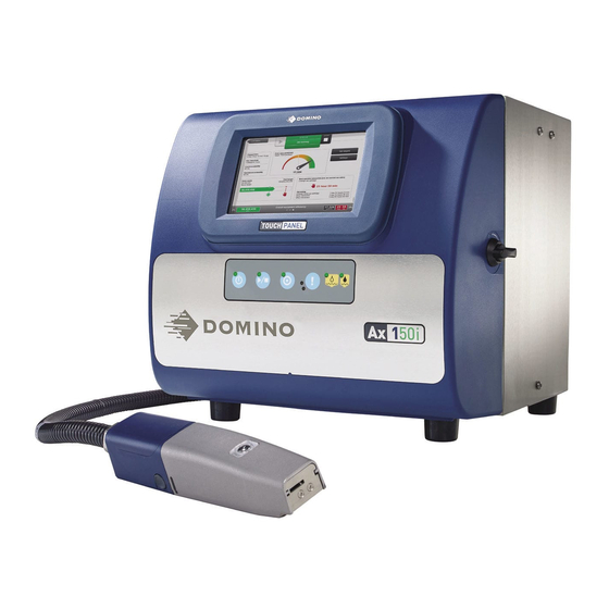
Page 20: Ax150I Printer
This is then indicated on both the TouchPanel user interface and on LEDs on the front of the cabinet. Note: ITM replacement intervals will vary according to use and ink type. Contact Domino for details. WARNING: The printer must be shut down and the power cable must be disconnected before the ITM can be removed. -
Page 21: Ax350I Printer
A range of TouchPanel options, i-Techx ink and electronics system and i-Pulse print head. The Ax350i can be controlled using a 10.4 inch Domino Type 3 TouchPanel or a 7 inch Domino Type 4 TouchPanel. The TouchPanel can be mounted on top of the stainless steel cabinet. The TouchPanel can also be mounted using a VESA 75 standard mounting, anywhere within range of the connecting cable. -
Page 22: Printer Configuration Labels
SYSTEM DESCRIPTION Printer Configuration Labels External Printer Configuration Label The label illustrated below is an example of the configuration label which is located on the rear of all Ax-Series printers. Printer Configuration Label The external configuration label contains the following information: •... -
Page 23: Internal Printer Configuration Label
SYSTEM DESCRIPTION Internal Printer Configuration Label WARNINGS: Protective equipment such as gloves and glasses must be worn when opening the printer’s ink compartment to access the internal configuration label. The ink compartment contains printer ink and make-up. Physical contact with printer ink or make-up can cause skin or eye damage. -
Page 24: Printer Specification
SYSTEM DESCRIPTION PRINTER SPECIFICATION Cabinet Ax150i Standard Finish: GRP front panel, brushed stainless steel cabinet. IP Rating: Designed to IP55 Dimensions: Width: 400mm (15.75") Depth: 394mm (15.50") Height: 373mm (14.70") Weight (dry): 16kg (35.3lb) Control Panel: 7 inch TouchPanel and polyester membrane touch buttons. Ax350i/Ax550i Standard Finish: Ax350i: Standard grade stainless steel... -
Page 25: External Connections
SYSTEM DESCRIPTION External Connections Interface communication: 1 x non standard DVI connection providing 24V DC, 500 mA Product Detect / Shaft 8-Way Socket Encoder Connector: Power connector: 3-Way Plug, cable supplied Hardware Pack Options: Extended Comms Pack: Powered HMI Port (P/N EPT022070) USB Port Extended IO Pack:... -
Page 26: Environment
SYSTEM DESCRIPTION Environment Temperature Range +5º to +45ºC (42ºF to 112ºF) (working)*: Temperature Range -20º to +60ºC (-4ºF to +140ºF) (machine dry - storage, wet (Storage): dependent upon fluids) Humidity: 10 - 90% RH (non-condensing) Electrical Supply: 100-240V 50-60Hz (nominal), 4A, single phase Auto ranging, 100W Acoustic Noise Level: Not more than 70 dBA... -
Page 27: Print Head
SYSTEM DESCRIPTION Print Head i-Pulse Standard Finish: Chassis: Stainless steel Wire box: Acetal Holster: Polymer (PTFE) coated aluminium Dimensions: Width: 50.3mm (1.98") Depth: 50.3mm (1.98") Height including conduit retaining nut: 243mm (9.57") Operating height with conduit at 90 degrees: 320mm (12.6") Weight including 3m conduit: 1.8kg (4lbs) Printer type, conduit Printer Type... -
Page 28: I-Pulse Duo (Ax350I/Ax550I Only)
SYSTEM DESCRIPTION i-Pulse Duo (Ax350i/Ax550i only) Standard Finish: Chassis: Stainless steel Wire box: Acetal Holster: Black anodised aluminium Dimensions: Width: 57mm (2.24") Depth (Max): 53mm (2.01") Height: 255mm (10") Weight: 2.8kg including 3m conduit (6.17lbs) Printer type, conduit Printer Type Conduit Length Nozzle Size length and nozzle size... -
Page 29: User Interface
SYSTEM DESCRIPTION User Interface TouchPanel Type 3 (Ax350i/Ax550i Only) Standard Finish: Cast aluminium (rear), nylon plastic (front) Mounting: Via angled bracket to cabinet top. VESA 75 standard mounting. Display: 10.4 inch SVGA full colour touch screen Dimensions: Width: 307mm (12.1") Height: 232mm (9.1") Depth: 75mm (3") Weight:... -
Page 30: Printer Control
SYSTEM DESCRIPTION Printer Control Cabinet Buttons There are four hardware buttons on the printer cabinet as illustrated below. It is necessary to press the buttons for at least 2-3 seconds as a precaution against accidental use. The cabinet buttons also carry an indicator light. All other functions are available using the QuickStep interface on the TouchPanel. -
Page 31: Cabinet Status Lights
SYSTEM DESCRIPTION Cabinet Status Lights There are a number of status lights on the printer cabinet as illustrated below. Cabinet Status Light Explanation Printer Off, Power The red light on the power button will illuminate to indicate that Connected the printer is connected to a power supply but the printer is not turned on. - Page 32 SYSTEM DESCRIPTION Cabinet Status Light Explanation Ink Level Alert If the ink level is ok, the light will be off. The ink light will illuminate to indicate when the ink level is low and the cartridge requires replacement. The ink light will flash on and off to indicate when the ink level is empty and the cartridge requires intimidate replacement.
-
Page 33: Qmm (Quality Management Module) Status Lights
SYSTEM DESCRIPTION QMM (Quality Management Module) Status Lights Ax-Series printers contain a QMM (Quality Management Module) to read and write data to RFID (Radio Frequency IDentification) tags on the make-up cartridge, ink cartridge and ITM. This enables the printer to alert the user when the ITM, ink or make-up cartridge need to be replaced to maintain reliable and efficient printer operation. -
Page 34: Quickstep
The QuickStep interface as displayed on the TouchPanel is shown below: QuickStep Interface Domino has developed QuickStep to be easy and intuitive to use. Training times, set up times and coding errors are all reduced with QuickStep. The operation of the printer using QuickStep is described in Part 4 : OPERATION. - Page 35 PART 3 : INSTALLATION CONTENTS PRINTER INSTALLATION ......................3-3 Cabinet Positioning ......................3-3 Installation Dimensions ......................3-4 Ax150i ..........................3-4 Ax350i/Ax550i ........................3-4 Ventilation ..........................3-5 Cabinet Mounting ......................... 3-5 Electrical Supply ........................3-5 External Connections ......................3-6 Ax150i ..........................3-6 Ax350i/Ax550i ........................
- Page 36 INSTALLATION THIS PAGE INTENTIONALLY LEFT BLANK EPT019297 Issue 1 November 2016...
-
Page 37: Printer Installation
INSTALLATION PRINTER INSTALLATION Cabinet Positioning WARNING: Care must be taken when moving the printer to avoid injury. Only personnel who have completed manual handling training and have the appropriate equipment should carry out this task. Note: For printer dry weight, see the specification on page 2-8. -
Page 38: Installation Dimensions
INSTALLATION Installation Dimensions Ax150i 400mm 394mm Ax150i Cabinet Ax350i/Ax550i 430mm 381mm Ax350i/Ax550i Cabinet EPT019297 Issue 1 November 2016... -
Page 39: Ventilation
Cabinet Mounting For total stability and to minimise vibration, the printer should be mounted on a Domino Cabinet Stand (P/N EPT024014) with the Stacking Kit (P/N EPT011760). If a Domino Cabinet Stand is not used, then the printer base must be secured using M6 mounting bolts. Spacers must be used to ensure the mounting bushes are flush with the mounting surface. -
Page 40: External Connections
INSTALLATION External Connections Ax150i Product Detect / Shaft Encoder Alarm Connector Beacon Connector Product Detect / Shaft Encoder Ethernet RS232 USB Type A GPIO Ax150i External Connections Left View Power Connector Ax150i External Connections Rear View EPT019297 Issue 1 November 2016... -
Page 41: Ax350I/Ax550I
INSTALLATION Ax350i/Ax550i Product Sensor / Shaft Encoder Product Sensor / TouchPanel Shaft Encoder Connector Extended GPIO (Option not shown) GPIO Beacon RS232 Connector Alarm Connector Ethernet Powered USB Type A Control Port Power Connector Ax350i/Ax550i External Connections EPT019297 Issue 1 November 2016... -
Page 42: Product Sensor / Shaft Encoder Pnp And Npn Selection
INSTALLATION Product Sensor / Shaft Encoder PNP and NPN Selection The picture below shows the PD/SE Printed Circuit Board with Lumberg connector and the PNP/NPN switches. The configuration of these switches will set the product sensor and shaft encoder inputs to either PNP or NPN. There are LED’s on the PCB to indicate that the signal is correct. -
Page 43: Touchpanel Installation (Ax350I/Ax550I)
INSTALLATION TOUCHPANEL INSTALLATION (Ax350i/Ax550i) Ax350i and Ax550i printers are operated either via a remote TouchPanel Type 3 or 4, or via a PC. TouchPanel Type 3 The TouchPanel Type 3 is a user interface with a 10.4 inch touch screen. The TouchPanel Type 3 has 2 USB ports and a connector to provide control of the Ax350i/Ax550i printers. -
Page 44: Touchpanel Type 4
INSTALLATION TouchPanel Type 4 The TouchPanel Type 4 is a user interface with a 7 inch touch screen. The TouchPanel Type 4 has 2 USB ports and a connector to provide control of the Ax350i/Ax550i printers. TouchPanel Type 4 Front View USB Type A TouchPanel to Printer Connection... -
Page 45: Touchpanel Mounting
INSTALLATION TouchPanel Mounting The TouchPanel Type 3 and Type 4 can be mounted to the top of the cabinet using the angled bracket and 8 screws provided. TouchPanels can also be mounted elsewhere on the production line using a VESA 75 bracket. CAUTION: To reduce the risk of damaging cables or equipment, securely route the TouchPanel cable away from moving equipment and other hazards. -
Page 46: Touchpanel Connectivity
INSTALLATION TouchPanel Connectivity The TouchPanel Type 3 and 4 are connected to the TouchPanel connector on the rear of the Ax350i/Ax550i printer. The TouchPanel will then display the user interface relating to that printer when the printer is turned on. CAUTION: To reduce the risk of damaging cables or equipment, securely route the TouchPanel cable away from moving equipment and other hazards. -
Page 47: Network Setup
NETWORK SETUP Ax-Series printers can be fully controlled over a network connection using a PC which has Domino QuickStep software installed. TouchPanel’s can also be used to control other printers on the same network. Only 1 printer can be controlled at the same time. - Page 48 INSTALLATION Cat.5 UTP RJ45 Cable Cat.5 UTP RJ45 Cable IP Address Fixed (192.168.1.c) Standard PC IP Address Fixed (192.168.1.a) Cat.5 UTP RJ45 Cable Cat.5 UTP RJ45 Cable IP Address Fixed (192.168.1.d) Standard PC IP Address Fixed (192.168.1.b) Cat.5 UTP RJ45 Cable 10/100 Ethernet IP Address Fixed network switch...
- Page 49 INSTALLATION Cat.5 UTP RJ45 Cable IP Address Fixed (192.168.1.a) Cat.5 UTP Standard PC RJ45 Cable IP Address fixed or dynamic Cat.5 UTP RJ45 Cable Network IP Address Fixed (192.168.1.b) Cat.5 UTP RJ45 Cable Cat.5 UTP IP Address Fixed RJ45 Cable (192.168.1.c) DHCP network server...
-
Page 50: Pc To Networked Printer Settings
INSTALLATION PC to Networked Printer Settings To setup the PC to Printer network settings: (1) Install the QuickStep programme on the PC which will be used to control the printer. (2) Ensure the printer is correctly connected to the network. (3) On the printer’s TouchPanel, select Home >... - Page 51 INSTALLATION (19) Enter the following information: Setting Name Explanation Name Enter the name of the printer. Type Select the type of printer which the QuickStep emulator is connecting to. In this case, select CIJ. IP address Enter the IP address of the printer. Host Enter the host name.
-
Page 52: Touchpanel To Networked Printers
INSTALLATION TouchPanel to Networked Printers One TouchPanel can control multiple printers in the same network if required. However, the TouchPanel can only connect to 1 printer at a time. Create a List of Favourite Printers It is recommended to create a list of favourite printers in the TouchPanel if there is more than 1 printer on the same network which the TouchPanel can connect to. -
Page 53: Connect To A Different Printer In The Network
INSTALLATION Connect to a Different Printer in the Network Details about the printer being controlled can be viewed by selecting Home > Setup > System Information. If a favourite list of printers has been set up, follow the procedure below to connect the TouchPanel to a different printer in the network. -
Page 54: Preparing The Ink System
INSTALLATION PREPARING THE INK SYSTEM Ax-Series Ink System The procedures described in this section must be followed when the ITM, ink and make-up cartridges are installed for the first time or following a long shut-down after ITM removal. 3-20 EPT019297 Issue 1 November 2016... -
Page 55: Itm Installation
INSTALLATION ITM Installation WARNING: Protective equipment such as gloves and glasses must be worn when this procedure is carried out. Physical contact with ink or make-up can cause skin or eye damage. Notes: (1) Paper towels (or similar) and wash are required for this procedure. (2) Waste paper towels will be contaminated with chemicals which are hazardous to the environment. - Page 56 INSTALLATION (4) Place paper towel (or similar) on top of the level sensor modules to catch excess fluid. Use the correct wash to remove any dried residual ink from the ink block valve face. Washing the ink block valve face (5) Place paper towel (or similar) under the ITM manifold pipes and lubricate the pipes with wash.
- Page 57 INSTALLATION (6) Insert the ITM between the retaining clips and firmly push the ITM manifold pipes into the ink block. Inserting the ITM (7) Continue pushing until the retaining clips engage with a click. Note: Ensure clips are fully engaged. ITM Clip Engagement (8) Close the printer ink cabinet.
-
Page 58: Ink And Make-Up Cartridge Installation
INSTALLATION Ink and Make-up Cartridge Installation WARNINGS: Protective equipment such as gloves and glasses must be worn when this procedure is carried out. Physical contact with printer ink or make-up can cause skin or eye damage. The print head must be placed in a wash station, or positioned over a beaker made of a conducting material and securely connected to earth (ground) in case the jet is misaligned out of the gutter. - Page 59 INSTALLATION (4) If the printer is not already on, press and hold the power button for 2 seconds to switch the printer on. (5) Before inserting the cartridges in the printer, hold the cartridges near the Quality Management Module (QMM) to check that the ink and make-up type is correct. The lights on the QMM will flash amber to indicate that the RFID tags are being read.
- Page 60 INSTALLATION (7) Push the make-up cartridge onto the make-up module manifold and push the ink cartridge onto the ITM. Make-up Cartridge Installation Ink Cartridge Installation 3-26 EPT019297 Issue 1 November 2016...
- Page 61 INSTALLATION (8) Rotate the ink cartridge clockwise and the make-up cartridge anti-clockwise, ensuring that the label is facing towards you. Make-up Cartridge Cartridge Ink and Make-up Cartridge Replacement (9) Check inside the printer for leaks. (10) Shut the ink compartment access door. (11) The ink system must now be primed, follow the procedure on page 3-28.
-
Page 62: Prime Ink System
INSTALLATION Prime Ink System WARNINGS: Protective equipment such as gloves and glasses must be worn when this procedure is carried out. Physical contact with printer ink or make-up can cause skin or eye damage. The print head must be placed in a wash station, or positioned over a beaker made of a conducting material and securely connected to earth (ground) in case the jet is misaligned out of the gutter. -
Page 63: Installation Wizard
INSTALLATION INSTALLATION WIZARD The Installation Wizard configures the language of the user interface, system pre-sets and basic settings and for the printer to operate. Note: The correct System Date and System Time values must be entered to print accurate date or time elements within labels. To start the printer and use the Installation Wizard: (1) If the printer is not already on, press and hold the power button for 2 seconds and wait... -
Page 64: Production Line Setup
INSTALLATION PRODUCTION LINE SETUP The following settings should be configured to set the printer up on a production line. Line Movement Home > Production line setup > Line movement The settings shown on the Line movement screen configure how the printing speed is set or measured. -
Page 65: Internal Encoder (Fixed Printing Speed) Setup
INSTALLATION Internal Encoder (Fixed Printing Speed) Setup Tools required: Metric ruler. To setup an internal encoder with a fixed printing speed: (1) Create a test label. (2) Select the Label tab in the label creator side menu and select Settings. (3) Scroll down to the Width setting and make a note of the value. -
Page 66: External Single Ended Shaft Encoder Setup
INSTALLATION External Single Ended Shaft Encoder Setup Tools required: Metric ruler. To setup an external single ended shaft encoder to measure the speed of the production line: (1) Create a test label. (2) Select the Label tab in the label creator side menu and select Settings. (3) Scroll down to the Width setting and make a note of the value. - Page 67 INSTALLATION (18) If missing strokes appear in the test print change the Stroke go multiplier setting to x2. This will increase the Encoder stroke resolution (pulses/stroke) by detecting a pulse on both the rising and falling edge of the shaft encoder input signal. (19) If missing strokes continue to appear in the test print, the Encoder stroke resolution (pulses/stroke) can be accurately set using the Digital gearbox multiplier and Digital gearbox divider settings.
-
Page 68: External Quadrature Shaft Encoder Setup
INSTALLATION External Quadrature Shaft Encoder Setup If the production line can change direction, a quadrature shaft encoder can be used to measure the production line’s speed and detect the direction of travel. Four different encoder modes are available to define the printers behaviour when the direction changes. To setup a quadrature shaft encoder: (1) Create a test label. - Page 69 INSTALLATION (17) If missing strokes appear in the test print change the Stroke go multiplier setting to x4. This will increase the shaft encoder resolution by detecting a pulse on both the rising and falling edge of the two shaft encoder input signal. (18) If missing strokes continue to appear in the test print, the Encoder stroke resolution (pulses/stroke) can be accurately set using the Digital gearbox multiplier and Digital gearbox divider settings.
- Page 70 INSTALLATION Backlash suppressed Printing will only occur when the production line moves in the forward direction. When the production line moves backward, printing is paused. Printing will resume as soon the production line moves in the forward direction. Production Line Direction <<...
-
Page 71: Print Trigger
INSTALLATION Print Trigger Home > Setup > Production Line Setup > Print Trigger Printing can be triggered by one of two different methods which are described in the table below. Note: It is recommended to use the external print trigger if the space between products varies on the production line. -
Page 72: External Print Trigger Setup
INSTALLATION External Print Trigger Setup To setup an external print trigger: (1) On the TouchPanel, select Home > Setup > Production line setup > Print trigger. (2) Select the Trigger by drop down setting and select External. (3) Select the Active level drop down setting and select whether a High or Low input signal will trigger a print. -
Page 73: Ink Jet Throw Distance Setup
INSTALLATION Ink Jet Throw Distance Setup WARNING: Protective equipment such as gloves and glasses must be worn when working on or near the printer. Physical contact with ink or make-up can cause skin or eye damage. The throw distance setting is used to define the distance between the bottom of the print head and the print surface. -
Page 74: Print Height Calibration Wizard
If any of the items are marked with a red cross, wait a few minutes to see if the ink system stabilises and a green tick appears. If the red cross remains, an engineer certified by Domino can investigate the fault. (5) Select the Next Screen icon. - Page 75 PART 4 : OPERATION CONTENTS Page QUICKSTEP INTERFACE ......................4-5 Home Screen ........................4-5 Setup Screen ........................4-7 Production Line Setup Screen ..................... 4-8 Print Optimisation Screen ....................4-9 Label Creator Screen ......................4-10 Information Screens ......................4-12 Connection and Consumable Screen ................4-13 Live Status Screen ......................
- Page 76 OPERATION Add a Counter Element ....................4-38 Add a Prompted Field Element ..................4-40 Add a Link Element ......................4-41 Add a Link Element ......................4-42 Add a Script Element ......................4-43 Add a Shift Code Element ....................4-44 Label Segments ........................4-45 Add a Segment .........................4-46 Lock Label Elements ......................4-47 Calculate Print Time ......................4-47 Preview Label ........................4-47...
- Page 77 OPERATION Alert ID Codes ......................... 4-66 Fault Finding ......................... 4-72 EPT019297 Issue 1 November 2016...
- Page 78 OPERATION THIS PAGE INTENTIONALLY LEFT BLANK EPT019297 Issue 1 November 2016...
-
Page 79: Quickstep Interface
OPERATION QUICKSTEP INTERFACE Home Screen When starting the printer, the following Home Screen is displayed. Start Button Stop Button Status Tab Information Bar Information Bar Label Finder Label Creator Lock Label User Production Name Name Line Setup Home Setup Print Button Optimisation QuickStep Home Screen... - Page 80 OPERATION Setting Name Explanation Information Bar Displays printer information. See “Information Screens” on page 4-12. Status Tab Displays printer status and alerts. If more than one alert is present, the highest priority alert is displayed. If an alert is displayed, select the Status Tab to show more information and to clear the alert.
-
Page 81: Setup Screen
OPERATION Setup Screen The Setup screen contains advanced printer settings, diagnostic tools and wizards. This screen is accessed by selecting Setup on the Home screen. The following illustration shows the Setup screen. Setup Screen EPT019297 Issue 1 November 2016... -
Page 82: Production Line Setup Screen
OPERATION Production Line Setup Screen The Production Line Setup screen contains print trigger, encoder and power settings which should be configured during printer installation. See “Production Line Setup” on page 3-30. This screen is accessed by selecting Production Line Setup on the Home screen. The following illustration shows the Production Line Setup screen. -
Page 83: Print Optimisation Screen
OPERATION Print Optimisation Screen The Print Optimisation screen contains settings which are used to make everyday adjustments to label appearance. This screen is accessed by selecting Print Optimisation on the Home Screen. The following illustration shows the Print Optimisation screen. Print height Print Delay (mm) -
Page 84: Label Creator Screen
OPERATION Label Creator Screen The Label Creator screen is used in label creation and label editing. Refer to “Creating and Editing a Label” on page 4-20. Label Zoom Options Save/Save as/Print Label View Calculate Print Time Element Moving Options Undo/ Redo Label Design Side... - Page 85 OPERATION Setting Name Explanation Element Moving Options Choose to move elements in the label design area by dragging them. Or, choose to display arrow buttons to move elements more precisely. Undo/Redo Undo or redo the previous action. EPT019297 Issue 1 November 2016 4-11...
-
Page 86: Information Screens
OPERATION Information Screens The Information Screens display detailed live information about the printer’s performance. To open the Information Screens: (1) Press the icon on the Information Bar. (2) Swipe the screen left, or right to go to the next or previous screen. (3) Press the icon to close the Information Screen. -
Page 87: Connection And Consumable Screen
OPERATION Connection and Consumable Screen The following illustration shows the Connection and Consumable screen. Connection and Next Screen Jet Information Level Make-up Level Information Connection and Consumable Screen Setting Name Explanation Next Screen Proceed to the Live Status screen. Connection and Shows connection and jet information about the printer: Consumable Information •... -
Page 88: Live Status Screen
OPERATION Live Status Screen The following illustration shows the Live Status screen. Previous Next Screen Screen Live Status Information Information Live Status Screen Setting Name Explanation Next Screen Proceed to the Overall Equipment Efficiency screen. Previous Screen Go back to the Connection and Consumable screen. Live Status Information Displays live status information about the printer. -
Page 89: Overall Equipment Efficiency Screen
OPERATION Overall Equipment Efficiency Screen The following illustration shows the Overall Equipment and Efficiency screen. Efficiency Data Previous Screen Targets Settings Print Rates Next Operator Interaction Information Print Counts Overall Equipment Efficiency Screen Setting Name Explanation Previous Screen Go back to the Live Status screen. Set Targets Set print rate and print count targets. -
Page 90: Start-Up And Shut Down
OPERATION START-UP AND SHUT DOWN Start-up Start-up From Power Off to the Ready State To start-up the printer from power off to the Ready state: (1) Ensure the power connector at the rear of the printer is connected to a power source. Note: The red status light on the power button will illuminate to indicate that the printer is connected to a power source. -
Page 91: Shut Down
OPERATION Shut Down Controlled Shut Down To shut down the printer in a controlled manner: (1) Press and hold the Power button for 2 seconds. (2) The printer will now begin shutting down in the following sequence: (a) A progress bar will be displayed on the TouchPanel screen. (b) The green indicator light on the power button will begin flashing. -
Page 92: Recommendations For A Long Shut Down (Dye Ink System)
OPERATION Recommendations for a Long Shut Down (Dye Ink System) The recommended procedure to prepare a printer with a dye ink system for a long shut down depends on the length of time the printer will be shut down for as explained below. Less Than 14 Days WARNING: Protective equipment such as gloves and glasses must be worn when... -
Page 93: Recommendations For A Long Shut Down (Heavy Duty Ink System)
OPERATION Recommendations for a Long Shut Down (Heavy Duty Ink System) The recommended procedure to prepare a printer with a heavy duty ink system for a long shut down depends on the length of time the printer will be shut down for as explained below. Less Than 7 Days WARNING: Protective equipment such as gloves and glasses must be worn when... -
Page 94: Creating And Editing A Label
OPERATION CREATING AND EDITING A LABEL Create a New Label To create a new label: (1) From the TouchPanel’s Home Screen, select Label creator. (2) Select Blank. (3) Select the Label name text box. (4) Use the on screen keyboard to enter a name which the label design will be saved as. (5) Select the green Tick icon. -
Page 95: Edit A Label Layout
OPERATION Edit a Label Layout To edit a label layout: (1) Open the label which requires editing. (2) In the side menu, select the Label tab. (3) Select the Edit menu. (4) The layout settings as described in the table below can now be edited. Setting Name Explanation Number of lines... -
Page 96: Label Settings
OPERATION Label Settings Each individual label design can be created and saved with its own custom print settings. The label settings can be accessed in the label creator’s side menu by selecting the Label tab and selecting the Settings menu. The available settings are described in the table below. -
Page 97: Forward And Reverse Offset
OPERATION Forward and Reverse Offset Forward offset is used to adjust the position of the label on the print surface. If the print head is on a traversing line the Reverse offset can also be set. Note: A global offset setting is also available to adjust the offset for all label designs, see page 4-56. -
Page 98: Inverse Mode
OPERATION Inverse Mode Inverse mode is used to invert an individual label design as shown in the illustration below. This setting can also be used on a traversing line to invert the label design for a specified number of times before inverting the label back. Furthermore, this setting can be configured to invert the label when the printer’s user port is activated. -
Page 99: Reverse Mode
OPERATION Reverse Mode Reverse mode is used to reverse an individual label design as shown in the illustration below. This setting can be configured to reverse the label design for a specified number of times, before reversing the label back for the same number of times. Furthermore, this setting can be configured to reverse the label when the printer’s user port is activated. -
Page 100: Repeat Mode
OPERATION Repeat Mode Repeat mode can be configured to repeatedly print an individual label design for a specified number of times after a single print trigger signal is received. Repeat mode can also be configured to repeatedly print the label design when a continuous print trigger signal is received. Note: A global repeat setting is available to repeat print all label designs, see page... - Page 101 OPERATION Setting Name Explanation Continuous Continuously repeat print the label when a constant print trigger signal is received by the printer. The printer will stop printing when the print trigger signal stops. When this option is selected, the settings described below will also be displayed: Repeat spacing mode - Select how the distance between each print is measured.
-
Page 102: Shift Codes
OPERATION Shift Codes Shift codes is used to create a shift code table which can be inserted into the label design. To create a shift code table (1) In the label creator’s side menu, select the Label tab. (2) Select the Settings menu. (3) Select Shift codes. -
Page 103: Label Elements
OPERATION Label Elements The text, barcode and graphic items which make up label designs are known as elements. The following pages explain how to add and edit different label elements. Add a Text Element To add a text element into a label design: (1) In the label creator’s side menu select the Element tab. - Page 104 OPERATION Setting Name Explanation Inter-character gap Vary the gap between text characters. (strokes) Range: 1-50 Invert black/white Invert the printed and unprinted parts of the text element. Invert Invert the text element. Reverse Reverse the text element. Open the keyboard to edit the text. Note: The keyboard type and language can be changed by selecting the appropriate icon at the bottom of the text...
-
Page 105: Unicode
OPERATION Unicode To add a Unicode character into a text element: (1) When editing or creating a new text element, select the Unicode icon in the text entry screen. (2) Enter the Unicode value: Common Unicode Characters 00A3 Pound (Sterling) 20AA Shekel (Israel) 0024... -
Page 106: Add A Barcode Element
OPERATION Add a Barcode Element Notes: (1) The printer can currently print 10x10, 12x12, 14x14, 16x16, 18x18, 20x20, 22x22, 24x24, 26x26, 32x32, 8x18, 8x32, 12x26, 12x36, 16x36, and 16x48 data matrix symbols. The amount of data that can be contained within a data matrix symbol is dependant on the data matrix size. - Page 107 OPERATION Setting Name Explanation Invert Flip the barcode upside down. Reverse Reverse the barcode. Rotation Rotate the barcode by 0° 90° 180° or 270°. Check digit algorithm If required, select a check digit algorithm. Default setting: None Quite zone: Left Add an empty area to the left of the barcode.
-
Page 108: Add A Graphic Element
OPERATION Add a Graphic Element To insert a graphic element into the label: (1) In the label creator’s side menu, select the Element tab. (2) Select the Add menu. (3) Select Graphics. (4) Select the required graphic from the Images folder. (5) Select the Save icon to save the change. -
Page 109: Edit A Logo
OPERATION Edit a Logo To edit a logo: (1) Select Home > Setup > Tools. (2) Select the Folder icon. (3) Select the logo which requires editing. (4) Edit the logo as required. (5) Save the logo using the Save or Save As icons. End of procedure. -
Page 110: Variable Label Elements
OPERATION Variable Label Elements Variable label elements are elements which contain variable data such as clocks, counters and shift codes. The following pages explain how to add and edit different variable label elements. Add a Clock Element To add a clock element into the label design: (1) In the Side-menu, select the Element tab. - Page 111 OPERATION Setting Name Explanation Offset If required, an offset value can be set in years, months, days, hours, minutes and seconds. Language Select the language: • Western • Arabic • Farsi (8) Select the green Tick icon to confirm the clock settings. (9) Select the green Tick icon to add the clock element to the label design.
-
Page 112: Add A Counter Element
OPERATION Add a Counter Element To add a counter element to the label design: (1) In the label creator’s side menu, select the Element tab. (2) Select the Add menu. (3) Select Text. (4) Select +Variable at the top of the screen. (5) Select +Create new... - Page 113 OPERATION Setting Name Explanation Language Select the language: • Western • Arabic • Farsi Store persisent counter Select when the counter value is saved: value • never • on print start • on print complete (8) Select the green Tick icon to confirm the counter settings. (9) Select the green Tick icon to add the counter element to the label design.
-
Page 114: Add A Prompted Field Element
OPERATION Add a Prompted Field Element When a label containing a prompted field element is sent to print, the operator will be prompted to update data in the prompted field element before printing can start. The type of data that can be entered into a prompted field element can be Time, Date or Text. To add a prompted field element into the label design: (1) In the Side menu select the Element tab. -
Page 115: Add A Link Element
OPERATION Add a Link Element A link element can be used to print data contained within another label element. For example, the data contained within a barcode can be linked and printed as human readable text elsewhere in the same label design. To add a link element into the label design: (1) In the Side menu select the Element tab. - Page 116 OPERATION Add a Link Element A link element can be used to print data contained within another label element. For example, the data contained within a barcode can be linked and printed as human readable text elsewhere in the same label design. To add a link element into the label design: (1) In the Side menu select the Element tab.
-
Page 117: Add A Script Element
OPERATION Add a Script Element The script element can be used to add a custom script into the label design. To add a script element into the label design: (1) In the Side menu select the Element tab. (2) Select the Add menu. (3) Select Text. -
Page 118: Add A Shift Code Element
OPERATION Add a Shift Code Element A shift code element can be used to print data from a shift code table. Note: A shift code table must be created before a shift code element can be added to the label design. To create a shift code table see page 4-28. -
Page 119: Label Segments
OPERATION Label Segments The label design can be split into segments. Each segment can be customised to improve print quality, lower ink consumption or to decrease the print time. The 3 settings available to customise each segment are Number of lines, Line height and Quality. The illustration below shows an example of a label design with a barcode element and a text element in 2 different segments. -
Page 120: Add A Segment
OPERATION Add a Segment To add a segment into a label design: (1) In the Label Creator, select Segment at the top of the screen. (2) In the side menu, select the Segment tab. (3) Select the Add menu. (4) Select the Add Segment icon. (5) The following segment settings can now be defined: Setting Name Explanation... -
Page 121: Lock Label Elements
OPERATION Lock Label Elements Label elements can be locked to stop them from being accidentally edited or moved within the label design. To lock a label element: (1) In the label creator’s side menu, select the Label tab. (2) Select the Manage menu. (3) Select the element to be locked from the list of elements, or select the element in the label design area. -
Page 122: Open And Edit A Label
OPERATION Open and Edit a Label To edit an existing label: (1) From the Home Screen, select Label finder. (2) Select the label which requires editing. The label will open in the Label Creator. To edit the content within the Label Creator: (3) Select an element to edit within the label design. -
Page 123: Delete A Label Element
OPERATION Delete a Label Element To delete an element within the label design: (1) Select the element to delete. (2) In the side menu, select the Element tab. (3) Select the Edit menu. (4) Select the Delete icon. (5) Select the Save icon to save the change. End of procedure. -
Page 124: Move A Label Element
OPERATION Move a Label Element To move an element within the label design: (1) Select the element to move. (2) Either: (a) Select the Drag icon and drag the element to move it. (b) Select the Arrows icon and use the arrows to move the selected element precisely. (3) Select the Save icon to save the change. -
Page 125: Label Store And File Management
OPERATION LABEL STORE AND FILE MANAGEMENT Selecting an Existing Label Note: Where no label is selected, “No label selected” will be displayed on the Home screen. To open an existing label: (1) On the Home Screen, select Label finder. (2) Open the required folder from the folder list displayed on the screen. (3) If the label name is known, select Search for a label... -
Page 126: Import Label(S)
OPERATION Import Label(s) Home > Setup > File Manager > USB To import labels into the printer from a USB flash drive: (1) Insert the USB flash drive containing the label files into the USB port on the TouchPanel. (2) Wait until the USB icon on the information bar turns green. (3) Select Home >... -
Page 127: Export A Label(S)
OPERATION Export a Label(s) Home > Setup > File Manager > USB To export a label from the printer to a USB flash drive: (1) Insert a USB flash drive into the USB port on the TouchPanel. (2) Wait until the USB icon on the information bar turns green. (3) Select Home >... -
Page 128: Backup Printer
OPERATION BACKUP PRINTER There are 3 types of file information that can be saved to a USB device, these are: Full, Labels and Service. These will save different information to a USB memory device: a Full backup will copy the entire printer configuration;... -
Page 129: Restore From A Backup
If restoring information to a different printer, it is essential that the printer hardware is of the same version level. Please contact Domino for advice. Only Full or Label backup files can be restored to a printer. The information in the backup file will override the current printer settings. -
Page 130: Editor Defaults
OPERATION EDITOR DEFAULTS Set the default label settings. New labels will use these defaults. Print Offset Home > Setup> Editor Defaults > Properties The Forward offset is used to adjust the position of the label on the print surface. If the print head is on a traversing line the Reverse offset can also be set. -
Page 131: Repeat Print
OPERATION Repeat Print Home > Setup > Editor Defaults > Properties Labels can be repeat printed using one of two different methods. Or, repeat printing can be turned off as described in the table below. Note: This is a global setting which will affect all label designs. To configure an individual label design to print repeatedly, see page 4-26. -
Page 132: Counted
OPERATION Counted To set Counted repeat printing, the following settings must be configured: Setting Name Explanation Repeat Select Counted. Repeat count Enter the number of times to repeat the current label. Note: The number of repeat counts is extra to the initial print, i.e. -
Page 133: Continuous
OPERATION Continuous To set Continuous Repeat Printing, the following settings must be configured: Setting Name Explanation Repeat Select Continuous. Repeat Spacing Type Select how the distance between prints is measured: Space by pitch - The distance between the start of one print and the start of the next print measured in strokes. -
Page 134: Clocks/Dates
OPERATION Clocks/Dates Home > Setup > Editor defaults > Clocks / dates View and change: • Hour codes. • Day of week codes. • Day of month codes. • Month codes. • Day names. • Month names. 4-60 EPT019297 Issue 1 November 2016... -
Page 135: Regional Settings
OPERATION REGIONAL SETTINGS Set the Language and Keyboard Home > Setup > Regional > Language & keyboard Set: • Language • Keyboard layout • IME Scheme • Primary currency. Set the Master Clock Home > Setup > Regional > Date & time Note: The correct System Date and System Time values must be entered to print accurate date or time elements within label designs. -
Page 136: Global Print Settings
OPERATION GLOBAL PRINT SETTINGS Note: Engineers certified by Domino can refer to the Engineers Reference Guide for further details of the functionality described in this section. Position / Orientation Home > Setup > Global print settings > Position / orientation... -
Page 137: Appearance
OPERATION Appearance Home > Setup > Global Print Settings > Appearance Select from the following check boxes: Setting Name Explanation Bold Print label in bold. (Set to 1 in the example below) Intercharacter gap Vary the gap between characters in the label. Activate via the check box. -
Page 138: Statuses, Alerts And Fault Finding
OPERATION STATUSES, ALERTS AND FAULT FINDING Statuses Shown below are some printer statuses and their explanations. Printer statuses are displayed on the Status tab at the top of the QuickStep interface. Status Name Explanation The ink jet is off and the printer will not print, but the user interface can still be used. -
Page 139: Alerts
OPERATION Alerts Alerts are displayed on the Status tab at the top of the QuickStep interface. When multiple alerts occur only the highest alert will be displayed. If multiple alerts occur, the full list of alerts can be viewed by selecting the status tab. Common alert ID codes, their causes and remedies are listed on page 4-66. - Page 140 3-40. Ink leak at nozzle. Check for ink drops around the nozzle and call an engineer certified by Domino to repair or replace the nozzle. Ink Level Below Minimum The ink level is running low. Fit a new ink cartridge, see page 5-4.
- Page 141 OPERATION Alert ID Description Possible Cause and Remedy Gutter Dry at Start-up The printer was not shut down correctly. Clean the print head, see page 5-17 and restart the printer. Blocked nozzle. Runt the nozzle unblocking wizard, see page 5-18. Dried ink in the gutter.
- Page 142 Label too long for the product. Check the printed label and reduce the label length. Inspection Required An inspection is required by an engineer certified by Domino. Contact the local support office to organise an inspection. Gutter Stall The gutter has stalled.
- Page 143 OPERATION Alert ID Description Possible Cause and Remedy Change ITM - ITM Ink The ITM which has been fitted is the wrong type. Type Incorrect Shut down the printer, remove the ITM and replace it with the correct type, see page 5-10.
- Page 144 OPERATION Alert ID Description Possible Cause and Remedy Insert Ink Cartridge - No No ink cartridge fitted. Valid Ink Cartridge Present Fit an ink cartridge, see page 5-4. Ink cartridge not fitted correctly Check that the ink cartridge is correctly fitted in the printer cabinet, see page 5-4.
- Page 145 OPERATION Alert ID Description Possible Cause and Remedy Misaligned jet at start-up The nozzle is blocked. Run the nozzle unblocking wizard, see page 5-18. The ink jet is misaligned. Check the ink jet alignment, see page 5-19. The gutter is blocked. Clean the print head, page 5-17.
- Page 146 OPERATION Fault Finding Issue Possible Cause Remedy Not Printing, error Gutter Dry is Blocked Nozzle. Home > Setup > Wizards > Nozzle displayed unblocking wizard. Ink on deflector plates and/or charge Blocked Nozzle With the printer switched off and electrode, possible faults could be: or dirty print unplugged, clean the print head.
- Page 147 PART 5 : MAINTENANCE CONTENTS Page GENERAL MAINTENANCE ....................... 5-3 Ink and Make-up Cartridge Replacement ................5-4 Make-Up Module Filter Replacement .................. 5-8 ITM Replacement ......................... 5-10 Air Filter Replacement ......................5-15 i-PULSE PRINT HEAD MAINTENANCE ..................5-17 Print Head Cleaning ......................5-17 Clearing a Blocked Nozzle ....................
- Page 148 MAINTENANCE THIS PAGE INTENTIONALLY LEFT BLANK EPT019297 Issue 1 November 2016...
-
Page 149: General Maintenance
MAINTENANCE GENERAL MAINTENANCE WARNINGS: Protective equipment such as gloves and glasses must be worn when working on or near the printer. Physical contact with ink or make-up can cause skin or eye damage. If the printer is ever operated in a way that allows it to print into a beaker, the beaker must be made of conducting material and be securely connected to earth (ground), as the electrostatic charges on the ink drops used for printing can cause a fire hazard. -
Page 150: Ink And Make-Up Cartridge Replacement
MAINTENANCE Ink and Make-up Cartridge Replacement WARNING: Protective equipment such as gloves and glasses must be worn when this procedure is carried out. Physical contact with printer ink or make-up can cause skin or eye damage. CAUTIONS: If the make-up cartridge is not replaced when needed, the make-up module will empty and the ink viscosity will go outside the printer’s operating limits. - Page 151 MAINTENANCE To replace the ink or make-up cartridge: (1) Open the access door to the printer’s ink compartment. (2) Remove the old cartridges by rotating the ink cartridge anti-clockwise and the make-up cartridge clockwise to free them before lifting the cartridge away. Make-up Ink Cartridge Cartridge...
- Page 152 MAINTENANCE (4) Insert a 6mm hex key into the top of the new cartridge, twist to break the sealing tab and remove the sealing tab. Breaking the Make-up Breaking the Ink Cartridge Cartridge Sealing Tab Sealing Tab (5) Push the ink cartridge onto the ITM, or push the make-up cartridge onto the make-up module.
- Page 153 MAINTENANCE (6) Rotate the ink cartridge clockwise and the make-up cartridge anti-clockwise. Ensure that the label is facing towards you. Make-up Cartridge Cartridge Ink and Make-up Cartridge Replacement (7) Check for leaks inside the printer. (8) Close the access door to the printer ink compartment. (9) Dispose of empty cartridges by following local waste disposal regulations.
-
Page 154: Make-Up Module Filter Replacement
MAINTENANCE Make-Up Module Filter Replacement WARNING: Protective equipment such as gloves and glasses must be worn when this procedure is carried out. Physical contact with printer ink or make-up can cause skin or eye damage. CAUTION: Cleanliness is of extreme importance. Ensure debris does not enter the make-up module during this process or the printer may become damaged. - Page 155 MAINTENANCE (5) Use the 6mm hex key to screw the new make-up filter into the make-up module. (6) Replace the make-up cartridge (if fitted). (7) Start the printer and check for leaks. (8) Shut the ink compartment access door. (9) Dispose of the old make-up filter by following local waste disposal regulations. End of procedure.
-
Page 156: Itm Replacement
MAINTENANCE ITM Replacement WARNINGS: The printer must be shut down and the power cable must be disconnected before the ITM can be removed. The ink system is pressurised. If the printer is not shut down ink will spray out of the ITM manifold over the person removing the ITM. - Page 157 MAINTENANCE (5) Pull the two ITM retaining clips upwards away from the ITM. Removing the ITM (6) Pull the ITM backwards, withdrawing the connecting manifold from the ink block and remove the old ITM. Notes: (1) If the ITM does not withdraw with moderate pressure, push the ITM fully forward (which will break any seal caused by dry ink) and try again.
- Page 158 MAINTENANCE (9) Place paper towel or similar on top of the level sensor modules to catch excess fluid and using wash, remove any dried residual ink from the ink block valve face. Washing the ink block valve face (10) Place paper towel or similar under the ITM manifold pipes and lubricate the pipes with wash.
- Page 159 MAINTENANCE (11) Insert the ITM between the retaining clips and push the manifold pipes into the ink block. Inserting the ITM (12) Continue pushing until the retaining clips engage with a click. ITM Clip Engagement EPT019297 Issue 1 November 2016 5-13...
- Page 160 MAINTENANCE (13) Re-connect the power lead to the rear of the printer. (14) Press and hold the power button for 2 seconds and wait for the printer to start. (15) Attach a new ink cartridge to the ITM or re-use the existing ink cartridge. See, “Ink and Make-up Cartridge Replacement”...
-
Page 161: Air Filter Replacement
MAINTENANCE Air Filter Replacement WARNING: Protective equipment such as gloves and glasses must be worn when this procedure is carried out. The air filter may contain hazardous particles. Air filter replacement is recommended after every 2000 hours of operation but may need to be replaced sooner depending on the operating environment. - Page 162 MAINTENANCE (3) Replace the air filter with a new unit. Note: Ensure the new air filter is correctly orientated by confirming the arrow symbols on the yellow filter moulding are pointing up. If the filter is inserted upside-down it will get stuck in the printer cabinet.
-
Page 163: I-Pulse Print Head Maintenance
MAINTENANCE i-PULSE PRINT HEAD MAINTENANCE Print Head Cleaning WARNING: Protective equipment such as gloves and glasses must be worn when this procedure is carried out. Physical contact with printer ink or make-up can cause skin or eye damage. CAUTION: The printer must be switched off before starting this procedure. If the printer is running whilst this procedure is carried out, wash will enter the gutter and may cause the viscosity of the ink to thin. -
Page 164: Clearing A Blocked Nozzle
If the nozzle is not clear after 2 attempts, contact the local support office to organise a visit from an engineer certified by Domino. Unless trained, do not attempt to remove the nozzle assembly. Removing the nozzle assembly can cause contamination to enter the ink system. -
Page 165: Ink Jet Alignment Check
MAINTENANCE Ink Jet Alignment Check WARNINGS: Protective equipment such as gloves and glasses must be worn when this procedure is carried out. Physical contact with printer ink or make-up can cause skin or eye damage. The print head must be placed in a wash station, or positioned over a beaker made of a conducting material and securely connected to earth (ground) in case the jet is misaligned out of the gutter. - Page 166 Ink jet in the centre of the gutter. Ink Jet Alignment Viewed from the Side (4) If the alignment is incorrect, an engineer certified by Domino can re-align the ink jet. (5) Replace the print head holster. End of procedure.
Need help?
Do you have a question about the AX Series and is the answer not in the manual?
Questions and answers
Tengo una pregunta la impresora imprime en un sentido Pero no imprime al regresar que puede pasar
The Domino AX Series printer may print in one direction but not when returning due to the encoder mode settings:
1. Backlash Mode: Printing only occurs during forward motion. When the line moves backward, printing pauses and a backlash count begins. Printing resumes when the count returns to zero after forward motion resumes.
2. Backlash Suppressed Mode: Printing also occurs only during forward motion, but it resumes immediately when forward motion restarts, without counting backward strokes.
In both modes, printing does not occur during backward movement.
This answer is automatically generated
can you pump the ink back to the bottle from the ITM
No, the ink cannot be pumped back to the bottle from the ITM on a Domino AX Series.
This answer is automatically generated
where can i find a list of alarms
You can find a list of alarms for the Domino AX Series on page 4-66 of the manual.
This answer is automatically generated
product number of air filter
The product number of the air filter for the Domino AX Series is DB015415.
This answer is automatically generated
air filter material number
The air filter material number for the Domino AX Series is EPT011443.
This answer is automatically generated
Domino Printer is stuck in "Connecting to printer" has been for over an hour and won't let me do anything. What can I do?
How to manually change date