Advertisement
Quick Links
Advertisement

Related Manuals for Tenma TEN01056


Summary of Contents for Tenma TEN01056
- Page 1 DC/AC CLAMP METER TEN01056...
-
Page 2: Safety Notes
Safety International Safety Symbols This symbol, adjacent to another symbol or terminal, indicates the user must refer to the manual for further information. This symbol, adjacent to a terminal, indicates that, under normal use, hazardous voltages may be present Double insulation SAFETY NOTES ... - Page 3 CAUTIONS Improper use of this meter can cause damage, shock, injury or death. Read and understand this user manual before operating the meter. Always remove the test leads before replacing the battery. Inspect the condition of the test leads and the meter itself for any damage before operating the meter.
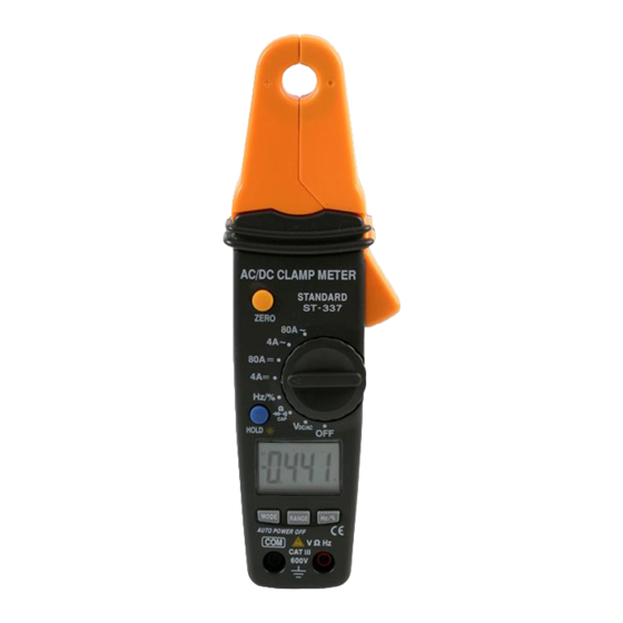
- Page 4 Meter Description 1. Current clamp 2. Clamp trigger 3. Safety protection ring 4. ZERO button 5. Data Hold and Backlight button 6. Mode select button 7. Range select button 8. Hz/%duty button 9. Rotary Function swith 10. LCD display 11. COM input jack 12.
-
Page 5: Specifications
Specifications Function Range & Accuracy (% of reading) Resolution DC Current 4.000 A DC ± (2.8% + 10 digits) 80.0 A DC ± (3% + 8 digits) AC Current ± (3.0% +10digits) 4.000 A AC (50/60Hz) 80.0A AC ± (3.0% + 8 digits) 400.0 mV DC ±... - Page 6 500.0Hz Sensitivity: 10Vrms min. @ 20% to 80% duty cycle 5.000kHz 50.00kHz 500.0kHz 5.000MHz 10.00MHz (1.2% reading + 2 Duty Cycle 0.5 to 99.0% digits) Pulse width: 100µs - 100ms, Frequency: 5Hz to 150kHz; Sensitivity: 10Vrms min. Analog output: (for ACA & DCA range), 10mV/Amp (20KHz at ±3dB) Accuracy: ±...
- Page 7 Clamp size Opening 0.9" (23mm) approx Diode Test Test current of 0.3mA typical; Open circuit voltage 1.5V DC typical. Continuity Check Threshold <150; Test current< 1mA “ ” is displayed Low Battery Indication “OL” is displayed Overrange Indication Measurements Rate 2 per second, nominal Input Impedance 7.8M...
-
Page 8: Operation
Operation NOTICES: Read and understand all warning and precaution statements listed in the safety section of this operation manual prior to using this meter. Set the function select switch to the OFF position when the meter is not in use. AC/DC Current Measurements WARNING: Ensure that the test leads are disconnected from the... - Page 9 DC/AC Voltage Measurements 1. Insert the black test lead into the negative COM terminal and the red test lead into the positive V terminal. 2. Set the function switch to the V position. 3. Select AC or DC with the MODE button. 4.
- Page 10 3. Press the MODE button until “ “ appears in the display. 4. Touch the test probes to the diode under test. Forward voltage will indicate 0.4V to 0.7V. Reverse voltage will indicate “OL”. Shorted devices will indicate near 0mV and an open device will indicate “OL”...
- Page 11 Read the frequency on the display. Analog Signal Output 1. Switch the function selector to DCA or ACA range. 2. Connect red test lead to “V” terminal and black one to the “ COM ” terminal. 3. Connect tip of the test leads to the meter or oscilloscope input terminal.
-
Page 12: Zero Button
Data Hold To freeze the LCD meter reading, press the data hold button. The data hold button is located on the left side of the meter (top button). While data hold is active, the HOLD display icon appears on the LCD. Press the data hold button again to return to normal operation. - Page 13 INFORMATION ON WASTE DISPOSAL FOR CONSUMERS OF ELECTRICAL & ELECTRONIC EQUIPMENT. When this product has reached the end of its life it must be treated as Waste Electrical & Electronic Equipment (WEEE). Any WEEE marked products must not be mixed with general household waste, but kept separate for the treatment, recovery and recycling of the materials used.
Need help?
Do you have a question about the TEN01056 and is the answer not in the manual?
Questions and answers