Table of Contents
Advertisement
Quick Links
TABLE OF CONTENTS
1 Safety Precautions----------------------------------------------- 3
1.1. General Guidelines---------------------------------------- 3
1.2. Caution for AC Cord (For GS only) ------------------- 4
1.3. Before Repair and Adjustment ------------------------- 5
1.4. Caution For Fuse Replacement------------------------ 5
1.5. Protection Circuitry ---------------------------------------- 5
1.6. Safety Part Information----------------------------------- 5
2 Warning -------------------------------------------------------------- 6
to Electrostatically Sensitive (ES) Devices---------- 6
3 Service Navigation ----------------------------------------------- 8
3.1. Service Information --------------------------------------- 8
4 Specifications ----------------------------------------------------16
5 Location of Controls and Components ------------------17
Model No.
Product Color: (K)...Black Type(For GN model only)
PAGE
Operations ------------------------------------------------- 17
5.2. iPod or iPhone Operation ------------------------------ 18
5.3. Using Bluetooth------------------------------------------- 19
5.4. Using the auxiliary input -------------------------------- 20
5.5. Listening to the Internet radio ------------------------- 20
5.6. Using the auto off function ----------------------------- 20
6 Disassembly and Assembly Instructions--------------- 21
6.1. Disassembly flow chart --------------------------------- 22
6.2. Types of Screws------------------------------------------ 23
6.3. Main Parts Location Diagram ------------------------- 23
6.4. Disassembly of Stand Unit----------------------------- 24
6.5. Disassembly of Net Frame Assembly--------------- 25
6.6. Disassembly of Front Panel Block ------------------- 25
6.7. Disassembly of iPod Block ---------------------------- 26
© Panasonic Corporation 2011. All rights reserved.
Unauthorized copying and distribution is a violation of
law.
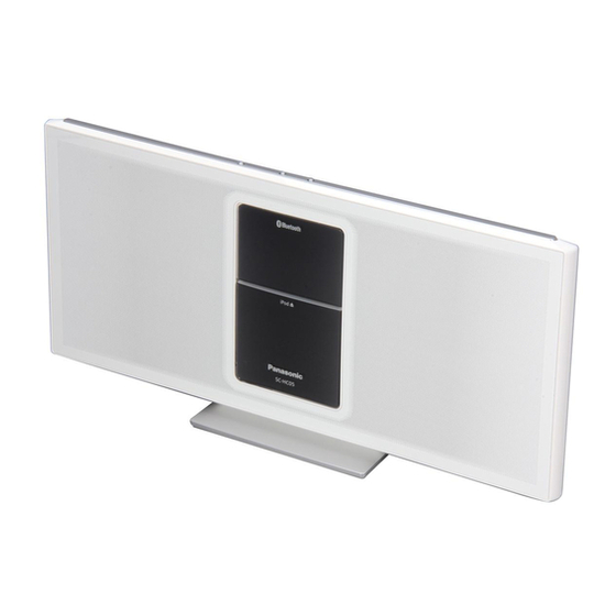
Compact Stereo System
SC-HC05GN
SC-HC05GS
(W)...White Type
PSG1105007CE
PAGE
Advertisement
Table of Contents

Related Manuals for Panasonic SC-HC05GN


Summary of Contents for Panasonic SC-HC05GN
-
Page 1: Table Of Contents
4 Specifications ----------------------------------------------------16 6.6. Disassembly of Front Panel Block ------------------- 25 5 Location of Controls and Components ------------------17 6.7. Disassembly of iPod Block ---------------------------- 26 © Panasonic Corporation 2011. All rights reserved. Unauthorized copying and distribution is a violation of law. - Page 2 6.8. Disassembly of Latch ----------------------------------- 27 6.9. Replacement of Damper ------------------------------- 28 6.10. Disassembly of iPod Cradle --------------------------- 29 6.11. Disassembly of Dock P.C.B and LED P.C.B. ------ 31 6.12. Replacement of iPod Cover --------------------------- 33 6.13. Disassembly of Lever Lock ---------------------------- 35 6.14.
-
Page 3: Safety Precautions
1 Safety Precautions 1.1. General Guidelines 1. When servicing, observe the original lead dress. If a short circuit is found, replace all parts which have been overheated or damaged by the short circuit. 2. After servicing, see to it that all the protective devices such as insulation barriers, insulation papers shields are properly installed. -
Page 4: Caution For Ac Cord (For Gs Only)
1.2. Caution for AC Cord (For GS only) -
Page 5: Before Repair And Adjustment
1.3. Before Repair and Adjustment Disconnect AC power, discharge unit AC Capacitors as such C702, C710, C725, C727 and C728 through a 10W, 1W resistor to ground. Caution : DO NOT SHORT-CIRCUIT DIRECTLY (with a screwdriver blade, for instance), as this may destroy solid state devices. After repairs are completed, restore power gradually using a variac, to avoid overcurrent. -
Page 6: Warning
2 Warning 2.1. Prevention of Electro Static Discharge (ESD) to Electrostatically Sensi- tive (ES) Devices Some semiconductor (solid state) devices can be damaged easily by static electricity. Such components commonly are called Elec- trostatically Sensitive (ES) Devices. Examples of typical ES devices are integrated circuits and some field-effect transistors and semiconductor “chip”... -
Page 7: Service Caution Based On Legal Restrictions
2.2. Service caution based on Legal restrictions 2.2.1. General description about Lead Free Solder (PbF) The lead free solder has been used in the mounting process of all electrical components on the printed circuit boards used for this equipment in considering the globally environmental conservation. The normal solder is the alloy of tin (Sn) and lead (Pb). -
Page 8: Service Navigation
3 Service Navigation 3.1. Service Information... - Page 13 connected Mode pause/Sleep BT LED On previous condition mode display ON: BT Talking Any key BT mode, Show No effect to phone connected Mode mode press BT LED On caller’s info operation from main set or RC ON: BT iPhone Press Aux Mode, Pause...
-
Page 16: Specifications
4 Specifications Amplifier Section RMS Output Power Stereo Mode 20 W per channel (6 Ω), 1 kHz, Front Ch (both ch driven) 10% THD Total RMS stereo mode power 40 W PMPO output power 450 W(GS) Terminals section Aux (rear) Terminal Stereo, 3.5 mm jack Speaker Section... -
Page 17: Location Of Controls And Components
5 Location of Controls and Components 5.1. Main Unit & Remote Control Key Button Operations... -
Page 18: Ipod Or Iphone Operation
5.2. iPod or iPhone Operation 5.2.1. Compatibility iPod/iPhone • For compatibility of iPod/iPhone please refer to Operating Instructions. -
Page 19: Using Bluetooth
5.3. Using Bluetooth... -
Page 20: Using The Auxiliary Input
5.4. Using the auxiliary input 5.5. Listening to the Internet radio 5.6. Using the auto off function... -
Page 21: Disassembly And Assembly Instructions
6 Disassembly and Assembly Instructions Caution Note: • This section describes the disassembly and/or assembly procedures for all major printed circuit boards & main compo- nents for the unit. (You may refer to the section of “Main components and P.C.B Locations” as described in the service manual) •... -
Page 22: Disassembly Flow Chart
6.1. Disassembly flow chart The following chart is the procedure for disassembling the casing and inside parts for internal inspection when carrying out the ser- vicing. To assemble the unit, reverse the steps shown in the chart below. -
Page 23: Types Of Screws
6.2. Types of Screws 6.3. Main Parts Location Diagram... -
Page 24: Disassembly Of Stand Unit
6.4. Disassembly of Stand Unit Caution : During assembling, ensure Stand Unit are seated properly into respective guides and locators of main unit. Step 1 : Remove 3 screws. Step 2 : Lift up the stand unit as arrow shown. -
Page 25: Disassembly Of Net Frame Assembly
6.5. Disassembly of Net Frame 6.6. Disassembly of Front Panel Assembly Block • Refer to “Disassembly of Net Frame Assembly” Step 1 : Gently lift up the Net Frame Assembly by release the 8 bosses in order of sequence (1) to (8) as shown. Step 1 : Remove 2 screws. -
Page 26: Disassembly Of Ipod Block
6.7. Disassembly of iPod Block Caution : During assembly, ensure the Damper Gear align to the guide. • Refer to “Disassembly of Net Frame Assembly” • Refer to “Disassembly of Front Panel Block” Step 1 : Remove 4 screws. Step 2 : Remove iPod Block as arrow shown. Caution : During disassembling, the Damper Gear may drop out, please keep it in the safe place for assembling use. -
Page 27: Disassembly Of Latch
6.8. Disassembly of Latch Step 2 : Press and release the both catches. Caution : During assembling, ensure the Latch is fully • Refer to “Disassembly of Net Frame Assembly” catched and inserted into the iPod Cradle. • Refer to “Disassembly of Front Panel Block” •... -
Page 28: Replacement Of Damper
6.9. Replacement of Damper 6.9.2. Assembly of Damper 6.9.1. Disassembly of Damper Step 1 : Slot the Damper into the hole as shown. • Refer to “Disassembly of Net Frame Assembly” Caution : During assembling, ensure the Damper is seated properly. -
Page 29: Disassembly Of Ipod Cradle
6.10. Disassembly of iPod Cradle Step 3 : While pressing the Push Close button, slightly lift up the iPod Bracket Assembly. • Refer to “Disassembly of Net Frame Assembly” Step 4 : Release the shaft from iPod Bracket Assembly as •... - Page 30 Step 6 : Relese the 12P FFC through the iPod Bracket Assem- Caution : During assembling the Cradle Spring, ensure that the one end of the spring is hooked onto the groove of bly as arrow shown. the iPod Cradle.. Step 7 : Remove the iPod Cradle as arrow shown.
-
Page 31: Disassembly Of Dock P.c.b And Led P.c.b
6.11. Disassembly of Dock P.C.B and Step 3 : Slightly lift up the iPod Bottom Ornament Assembly. LED P.C.B. • Refer to “Disassembly of Net Frame Assembly” • Refer to “Disassembly of Front Panel Block” • Refer to “Disassembly of iPod Block” •... - Page 32 Step 6 : Remove 2 screws. Caution : During assembling, ensure the Dock P.C.B. is seated properly onto guides. Step 7 : Remove the BT Lighting Guide as shown. Step 10 : Lift up the LED P.C.B.. Step 8 : Remove 2 screws. Step 11 : Remove both Dock P.C.B.
-
Page 33: Replacement Of Ipod Cover
6.12. Replacement of iPod Cover Caution : During assembling, ensure the LED P.C.B is seated properly onto slots. • Refer to “Disassembly of Net Frame Assembly” • Refer to “Disassembly of Front Panel Block” • Refer to “Disassembly of iPod Block” •... - Page 34 6.12.2. Assembly of iPod Cover Step 4 : Remove the iPod Cover with Spring Cover as shown. Caution : Keep the Spring Cover in the safe place and place it back during assembling. Step 1 : Hook the Spring Cover onto guide. Step 2 : Lift up the Spring Cover while slot the iPod Cover into the hole.
-
Page 35: Disassembly Of Lever Lock
6.13. Disassembly of Lever Lock Step 4 : Slightly push the iPod Cover inward. Step 5 : Insert the iPod Cover into the hole. • Refer to “Disassembly of Net Frame Assembly” Caution : Ensure the shaft of the iPod Cover is seated •... -
Page 36: Disassembly Of Release Button Assembly
6.14. Disassembly of Release Button Step 3 : Press the catches to release from Holder Button . Caution : During assembling, ensure the Release Assembly Button is fully catched onto the Holder Button. • Refer to “Disassembly of Net Frame Assembly” •... -
Page 37: Disassembly Smps Unit
6.15. Disassembly SMPS Unit Step 3 : Release both wire tie. Caution : Ensure the Speaker Wire L is tie back during • Refer to “Disassembly of Net Frame Assembly” assembly of SMPS Unit. • Refer to “Disassembly of Front Panel Block” Step 1 : Remove 4 screws. - Page 38 Step 4 : Slightly shift up the Top Ornament Assembly as Step 7 : Remove the SMPS Unit as arrow shown.. shown. Caution : Avoid touching the Remote Sensor during disas- sembly of SMPS Unit. Caution : Ensure the 2P Wire and 6P Wire Cable are dressed into grooves and guides as shown during assem- bling of SMPS Unit.
-
Page 39: Disassembly Smps P.c.b
6.16. Disassembly SMPS P.C.B. Step 3 : Gently lift up the SMPS Shield Plate as arrow shown. • Refer to “Disassembly of Net Frame Assembly” • Refer to “Disassembly of Front Panel Block” • Refer to “Disassembly of SMPS Unit” Step 1 : Lift up the Himelons. - Page 40 Step 6 : Release 2P wire from the gap of PC Sheet Bottom. Caution : During assembling, ensure the 2P Wire and 6P Wire Cable dressing properly. Step 7 : Lift up the SMPS P.C.B as shown. Caution : During assembling, ensure SMPS P.C.B. is Step 8 : Slightly fold the PC Sheet Bottom as shown.
-
Page 41: Disassembly Top Ornament Assembly
6.17. Disassembly Top Ornament 6.18. Disassembly SW/IR/Power-LED Assembly P.C.B. and Power Button • Refer to “Disassembly of Net Frame Assembly” • Refer to “Disassembly of Net Frame Assembly” • Refer to “Disassembly of Front Panel Block” • Refer to “Disassembly of Front Panel Block” •... -
Page 42: Disassembly Audio P.c.b
6.19. Disassembly Audio P.C.B. Step 3 : Remove the Power Button as shown. Caution : During assembling, ensure the holes are aligned • Refer to “Disassembly of Net Frame Assembly” to their respective guides on the Top Ornament as shown. •... -
Page 43: Disassembly Line Filter P.c.b. And Ac-In P.c.b
6.20. Disassembly Line Filter P.C.B. Caution : During assembling, ensure the AC Inlet Jack is seated properly onto the guides. and AC-In P.C.B. • Refer to “Disassembly of Net Frame Assembly” • Refer to “Disassembly of Front Panel Block” Step 1 : Remove 2 screws. Step 3 : Remove 2 screws. - Page 44 Step 5 : Remove 2 screws. Caution : During assembling, ensure the 2P Wire is dress- ing properly onto the guide. Step 6 : Detach 2P Wire at the connector (CN3) on the Line Fil- ter P.C.B.. Step 8 : Remove 2 screws. Step 9 : Remove both the Line Filter P.C.B.
-
Page 45: Disassembly Main P.c.b
6.21. Disassembly Main P.C.B. Caution : During assembling, ensure the 2P Wire is dress- ing properly onto the groove of the Line Filter Bracket. • Refer to “Disassembly of Net Frame Assembly” • Refer to “Disassembly of Front Panel Block” •... - Page 46 Step 5 : Remove 3 screws. Step 8 : Remove 4 screws. Step 6 : Remove 1 screw. Step 9 : Remove the PWB Brackets. Caution : During assembling, ensure the PWB Brackets is seated properly onto the hole. Step 7 : Lift up and remove the Speaker Panel R Assembly.
- Page 47 Step 10 : Detach 4P Wire at the connector (CN902) on the Step 12 : Desolder the 3 points. Audio P.C.B.. Step 13 : Remove the Main P.C.B.. Step 11 : Lift up and remove the Main P.C.B. as shown.
-
Page 48: Disassembly Passive Radiator (Sp6)
6.22. Disassembly Passive Radiator 6.23. Disassembly Front Speaker (SP6) (SP2) • Refer to “Disassembly of Net Frame Assembly” • Refer to “Disassembly of Net Frame Assembly” • Refer to “Disassembly of Front Panel Block” Step 1 : Remove 4 screws. •... - Page 49 Step 3 : Detach 2P Wire (Speaker Wire L) at the connector Step 6 : Remove 4 screws. (CN300) on the Main P.C.B.. Step 7 : Detach 2P Wire (Speaker Wire L) from the groove. Step 4 : Release 2P Wire (Speaker Wire L) from the guides. Caution : During assembling, ensure the 2P Wire (Speaker Wire L) is dressing properly onto the groove as shown.
-
Page 50: Disassembly Piezo Unit (Sp8)
6.24. Disassembly Piezo Unit (SP8) Step 9 : Desolder the red (+) speaker wire and black (-) speaker wire. • Refer to “Disassembly of Net Frame Assembly” Step 10 : Remove Front Speaker (SP2). • Refer to “Disassembly of Front Panel Block” •... -
Page 51: Disassembly Passive Radiator (Sp4)
6.25. Disassembly Passive Radiator 6.26. Disassembly Passive Radiator (SP4) (SP5) • Refer to “Disassembly of Net Frame Assembly” • Refer to “Disassembly of Net Frame Assembly” • Refer to “Disassembly of Front Panel Block” • Refer to “Disassembly of SMPS Unit” Step 1 : Remove 4 screws. -
Page 52: Disassembly Front Speaker (Sp1)
6.27. Disassembly Front Speaker Step 3 : Detach 2P Wire (Speaker Wire R) at the connector (CN301) on the Main P.C.B.. (SP1) Step 4 : Lift up the Himelons. • Refer to “Disassembly of Net Frame Assembly” Caution : Replace the Himelons if they are torn during dis- assembling. - Page 53 Step 7 : Remove 4 screws. Step 10 : Desolder the red (+) speaker wire and black (-) Step 8 : Detach 2P Wire (Speaker Wire R) from the groove. speaker wire. Caution : During assembling, ensure the 2P Wire (Speaker Step 11 : Remove Front Speaker (SP1).
-
Page 54: Disassembly Piezo Unit (Sp7)
6.28. Disassembly Piezo Unit (SP7) 6.29. Disassembly Passive Radiator (SP3) • Refer to “Disassembly of Net Frame Assembly” • Refer to “Disassembly of Front Panel Block” • Refer to “Disassembly of Net Frame Assembly” • Refer to “Disassembly of SMPS Unit” •... -
Page 55: Service Position
7 Service Position Note: For description of the disassembly procedures, see the Section 6 Step 11 : Connect then 12P FFC at the connector (CN500) on 7.1. Checking & Repairing of Main Main P.C.B.. P.C.B. (Side A) Step 1 : Remove of Net Frame Assembly. Step 2 : Remove of Front Panel Block. -
Page 56: Checking & Repairing Of Main P.c.b. (Side B)
7.2. Checking & Repairing of Main Step 4 : Connect then 12P FFC at the connector (CN500) on Main P.C.B.. P.C.B. (Side B) • Refer to (Step 1) to (Step 7) of item 7.1 Step 1 : Connect then 6P wire cable at the connector (CN100) on Main P.C.B.. -
Page 57: Block Diagram
8 Block Diagram 8.1. Control & Signal Diagram... -
Page 58: Voltage / Current / Ground Diagram
8.2. Voltage / Current / Ground Diagram... -
Page 59: Wiring Connection Diagram
AC 110 to 240 V, 50/60 Hz(GS) W1A* AC-In P.C.B. (SOLDER SIDE) Black SMPS P.C.B. W2A* (SOLDER SIDE) CAUTION RISK OF ELECTRIC SHOCK AC VOLTAGE LINE. PLEASE DO NOT TOUCH THIS P.C.B (SC-HC05GN/GS) WIRING CONNECTION DIAGRAM NOTE: " * " REF IS FOR INDICATION ONLY. -
Page 60: Schematic Diagram
10 Schematic Diagram 10.1. MAIN CIRCUIT (1/2) SCHEMATIC DIAGRAM - 1 MAIN CIRCUIT SC-HC05GN/GS MAIN CIRCUIT... -
Page 61: Main (2/2), Sw/Ir/Power-Led, Audio, Dock & Led Circuit
10.2. MAIN (2/2), SW/IR/POWER-LED, AUDIO, DOCK & LED CIRCUIT SCHEMATIC DIAGRAM - 2 MAIN CIRCUIT LED CIRCUIT DOCK CIRCUIT AUDIO CIRCUIT SC-HC05GN/GS MAIN/SW/IR/POWER-LED/AUDIO/DOCK/LED CIRCUIT SW/IR/POWER-LED CIRCUIT... -
Page 62: Smps, Line Filter & Ac-In Circuit
4.7uF/50V 2.2M TEA1733LT C716 0.22uF IC700 R701 D715 UDZSTE-1730B C709 C719 0.1uF C714 1000PF F751 K5G312Y00007 T3.15AL 250V C702 C725 P751 0.1uF 0.1uF Z752 L702 IC701 AC-IN CIRCUIT C722 56PF MM1431CU C0DBZMC00006 LINE FILTER CIRCUIT SC-HC05GN/GS SMPS/LINE FILTER/AC-IN CIRCUIT ZJ702... -
Page 63: Exploded View And Replacement Parts List
52-3 W905A (LED P.C.B.) 52-8 52-1 J901 *W905 52-9 (DOCK P.C.B.) CN901 47-2 47-1 53-1 53-3 53-2 58-22 62-1 51-4 58-20 57-10 57-9 62-2 52-10 REAR VIEW SC-HC05GN-K/W, GS-W NOTE: " * " REF IS FOR INDICATION ONLY. CABINET DRAWINGS... - Page 64 CN900 50-7 51-2 51-1 51-3 (SW/IR/POWER-LED P.C.B.) (SMPS P.C.B.) 52-4 56-3 50-6 52-5 52-6 55-31 52-7 43-2 55-32 55-8 37-2 SC-HC05GN-K/W,GS-W 55-7 NOTE: " * " PART IS NOT SUPPLIED / REF IS FOR INDICATION ONLY. CABINET DRAWINGS 55-6 55-5...
- Page 65 11.1.2. Packaging (FOR GS ONLY) (FOR GS ONLY) (FOR GN ONLY) (FOR GS ONLY) ACCESSORIES BAG OI BOOK P2-1 P2-2 SC-HC05GN/GS F R O N SC-HC05GN-K/W,GS-W PACKAGING DRAWINGS...
- Page 67 11.1.3. Mechanical Replacement Parts List Safety Ref. Part No. Part Name & QTY Remarks Description Safety Ref. Part No. Part Name & QTY Remarks VUEMPLGHC05 POWER LIGHTING Description GUIDE CABINET & CHASSIS 21-1 VUEMPBHC05 PWB BRACKET 21-2 VUEMPBHC05 PWB BRACKET VUEMNAHC05PW NET FRAME ASS'Y GN/GS-W 21-3...
- Page 68 Safety Ref. Part No. Part Name & QTY Remarks Safety Ref. Part No. Part Name & QTY Remarks Description Description VUEMMPSHC05 SMPS MIDDLE PC 55-19 VUEM0401SS SCREW SHEET 55-20 VUEM0401SS SCREW VUEMLFSHC05 LINE FILTER PC 55-21 VUEM0401SS SCREW SHEET 55-22 VUEM0401SS SCREW VUEMAPSHC05...
-
Page 69: Electrical Replacement Parts List
11.2. Electrical Replacement Parts List Safety Ref. Part No. Part Name & QTY Remarks Description Safety Ref. Part No. Part Name & QTY Remarks J901 VUEEIJHC05 JK IPOD Description IPSG1105 PRINTED CIRCUIT BOARDS PCB1 VUEEMPBHC05 MAIN P.C.B PCB2 VUEEKPBHC05 KEY P.C.B PCB3 VUEESBDHC05E SMPS P.C.B WIRES...
Need help?
Do you have a question about the SC-HC05GN and is the answer not in the manual?
Questions and answers