Table of Contents
Advertisement
Quick Links
IIST010-03
Digitale 3-Phasen Energiezähler
80 A
Direktanschluß bis
- Wandlerstromanschluß für
Bedienungsanleitung
digitale Wirk-/Blindenergie Zähler mit Anzeige der
aktuellen Wirk- und Blindleistung
kommunikationsfähig
Kode
14.01.320 EM3-80
14.01.321 EM3-80 (MID) Digitaler 3-Phasen Energiezähler für Direktanschluß
14.01.310 EM3-5
14.01.311 EM3-5 (MID) Digitaler 3-Phasen Energiezähler für
Die Installation muß von einer Elektrofachkraft oder unter deren Leitung und Aufsicht
durchgeführt und geprüft werden. Bei Arbeiten am Meßgerät, Netzspannung abschalten!
1) Im Display dargestellte Größen
1a) Energie
• Darstellung nur auf Zählern mit Digitalanzeige bis max. 8 Stellen:
Bzg. Bezeichnung
E1 bezogene Wirkenergie
E2 abgegebene Wirkenergie
E3 bezogene Blindenergie
E4 abgegebene Blindenergie
E5 bezogene Wirkenergie
E6 abgegebene Wirkenergie
E7 bezogene Blindenergie
E8 abgegebene Blindenergie
1b) Leistung
• Darstellung mittels Balkenanzeige und Anzeige mit 3 Stellen:
Bzg. Leistung
P1 bezogene Wirkleistung
P2 abgegebene Wirkleistung
P3 bezogene Blindleistung
P4 abgegebene Blindleistung
P5 bezogene Wirkleistung
P6 abgegebene Wirkleistung
P7 bezogene Blindleistung
P8 abgegebene Blindleistung
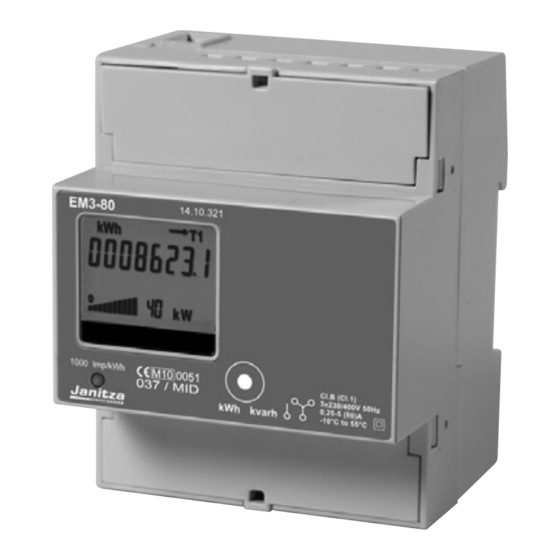
2) Display-Darstellung (siehe Display Beschreibung)
• Grüne, rückbeleuchtete LCD-Anzeige
• Die verschiedenen Anzeigeebenen werden mit der Steuerungstaste angewählt.
3) Bedienung
• Die große Anzahl von Meßgrößen macht eine Darstellung der Daten in 4 Anzeigeebenen erforderlich:
A
Default
B
Energiezählerstände (Gesamtwerte L)
C
Energiezählerstände (pro Phase)
D
Diagnostikseiten: Softwarestand, Prüfsumme, Displaysegmentekontrolle.
A) Anzeigeebene Default
• Es wird nur die momentane summierende Wirkenergie angezeigt. Es können folgende summierende
Zählerstände registriert werden: Wirkenergie Bezug und Abgabe Pfeil
Pfeil
) in Tarif 1 und Tarif 2
• Balkendiagramm in Prozent der Wirkleistung in Schritten von 10% der gemessenen Leistung im
Verhältnis der Gesamtleistung.
• Anzeige des Wandlerverhältnis des Stromwandlers, Primärseite (CT...) von 5 bis 9999.
• Mit erstmaligen Drücken der Steuertaste wird die Rückbeleuchtung aktiviert.
• Über nochmaliges Drücken der Steuertaste erscheint di Anzeigeebene aller Energiezählerstände
(Gesamtwerte Phasen L)
• Die Beleuchtung der Anzeige wird nach 40 Sekunden Inaktivität automatisch ausgeschalten und
es erscheint die Default Anzeige.
B) Anzeigeebene aller Energiezählerstände (Gesamtwerte L) E1 bis E8 siehe Tabelle
• In dieser Anzeigeebene werden die Gesamtenergiezählerstände dargestellt.
• In der Anzeige der laufenden Messung erscheint auch die Balkendiagrammanzeige der relativen
Leistung.
• Um in die Energiezählerstände "pro Phase" zukommen die Steuerungstaste ca 4 Sekunden lang
gedrückt halten. Nach 40 Sekunden Inaktivität erscheint automatisch die Default Anzeigeebene (A)
und die Rückbeleuchtung erlischt.
C) Anzeigeebene aller Energiezählerstände (pro Phase) E1 bis E8 siehe Tabelle
• Um alle Energieregister je Phase (Wirk-und Blindenergie) für aufgenommene und abgegebene
Energie für T1 und T2 in einer Schleife zu sehen, Steuertaste 4 Sekunden drücken.
• Um in die Diagnostikseiten zu kommen die Steuertaste ca 10 Sekunden lang gedrückt halten.
• Nach 40 Sekunden Inaktivität erscheint automatisch die Default Anzeigeebene (A).
D) Anzeigeebene Diagnostikseiten
• Es wird der Displaytest aktiviert. Bei nochmalige Betätigung der Steuerungstaste erscheint die
eingesetzte Firmware Version und die angelaufende Prüfsumme im Speicher.
3.1) Rückstellung aller Energieregister (nur für Kode 14.01.320 und 14.01.310)
• Wenn die Steuerungstaste länger als 20 Sekunden gedrückt wird erscheint die Schrift "
• Erst nach nochmaligen Drücken der Steuerungstaste für mindestens 4 Sekunden werden alle
Energieregister auf NULL gestellt.
• Wenn die Steuerungstaste nicht noch einmal gedrückt wird, kehrt die Anzeige ohne Rückstellung nach
4 Sek. zur Ausgangsanzeige zurück.
• Die Rückstellung bei Modellen mit Mid-Beglaubigung ist nicht verfügbar
3.2) Fehleranzeige "Error"
• Wenn im Display die Anzeige "
und der Energiezähler muß ausgetauscht werden.
Stand 01-01-2011
.../5 A
bis 10.000/5 A
Modell
Beschreibung
Digitaler 3-Phasen Energiezähler für Direktanschluß
0.25-5 (80) A - 2 Tarife - 2 SO
0.25-5 (80) A - 2 Tarife - 2 SO (MID geeicht)
Digitaler 3-Phasen Energiezähler für
Wandlerstromanschluß ... /5 A bis 10.000/5 A
0.05 ... 5 (6) A - 2 Tarife - 2 S0
Wandlerstromanschluß ... /5 A bis 10.000/5 A
0.05 ... 5 (6) A - 2 Tarife - 2 S0 (MID geeicht)
WARNUNG
Einheit
Symbole
L L1 L2 L3
MWh/kWh/Wh
•
•
MWh/kWh/Wh
•
•
Mvarh/kvarh/varh
•
•
Mvarh/kvarh/varh
•
•
MWh/kWh/Wh
•
•
MWh/kWh/Wh
•
•
Mvarh/kvarh/varh
•
•
Mvarh/kvarh/varh
•
•
Einheit
Symbole
L
MW/kW/W
•
MW/kW/W
•
Mvar/kvar/var
•
Mvar/kvar/var
•
MW/kW/W
•
MW/kW/W
•
Mvar/kvar/Var
•
Mvar/kvar/Var
•
(Export Pfeil
" oder "
" erscheint, liegt eine Fehlfunktion vor
DEUTSCH
Three-phase Digital Energy meters
Direct connection
Installation must be carried out and inspected by a specialist or under his supervision.
1) Quantities displayed
1a) Energy
• They are displayed on the main 8 digits counter:
Ref.
Energy
Tarif
E1
Active Absorbed
•
•
T1
E2
Active Supplied
•
•
T1
E3
Reactive Absorbed
•
•
T1
E4
Reactive Supplied
•
•
T1
E5
Active Absorbed
•
•
T2
E6
Active Supplied
•
•
T2
E7
Reactive Absorbed
•
•
T2
E8
Reactive Supplied
•
•
T2
1b) Power
• Powers are displayed on the bar indicator and also on the 3 digits secondary counter:
Ref.
Power
Tarif
P1
Active Absorbed
T1
P2
Active Supplied
T1
P3
Reactive Inductive
T1
P4
Reactive Capacitive
T1
P5
Active Absorbed
T2
P6
Active Supplied
T2
P7
Reactive Inductive
T2
P8
Reactive Capacitive
T2
2) Display View (see quantities displayed)
• A green backlighted LCD display.
• With the front push button all register will appear.
3) User informations
• A quantity of informations are available on the display. They are divided into 4 groups:
A
Default Page (currently growing Active Energy)
B
System Energy Registers ( L)
C
Phases Energy Registers (L1, L2 and L3)
D
Diagnostic Page
A) Default Page (currently growing Active Energy)
• The value of the currently growing Active 3-phase Energy is represented (or the last one that has
grown).
The Energy is always Active, and may be Active Consumed (right arrow), Active Generated (left arrow),
with Tariff T1 or T2, depending on the current Energy flowing.
• The value of currently flowing Active Power is visible (3 digits field), together with a dedicated
oder Import
bar-graph representing the percentage of the flowing power (10% division of the bar graph)
• In models with external CT, also the value of nominal value of primary winding current (5 to 9999)
appears below the energy value
• A short keypress of the "command button" switches the backlight ON. A further short keypress enable
the visualisation of system energy registers.
• If the command button is not pushed for 40 seconds, the backlight is automatically switched off, and
the display returns to the default page
B) System Energy Registers ( L) E1 to E8 see Table
• This group is dedicated to show the System ( L) Energy registers, E1 to E8, as described in
the above table.
• A short keypress of the "command button" allows to see all 8 registers, one at a time
• If the current rate corresponds to that of energy represented on the display, also the power and the
bar-graph are represented
• By keeping the command button pushed for at least 4 seconds, the L1 Phase Energy registers group
representation on display is enabled. If the command button is not pushed for 40 seconds, the
backlight is automatically switched off, and the display returns to the default page
C) Phases Energy Registers (L1, L2 & L3) E1 to E8 see Table
• This group is dedicated to show the Phase Registers (with the same criteria of the System Energy
registers). Initially, L1 group registers are displayed. A short keypress of the "command button"
allows to see all 8 registers, one at a time
• By keeping the command button pushed for at least 4 seconds (less than 10 seconds), the L2 Phase
Energy registers group representation on display is enabled. In the same way, once selected L2
registers, one can push the button for 4 seconds and start to see the L3 registers group.
• If the command button is not pushed for 40 seconds, the backlight is automatically switched off,
and the display returns to the default page
• By keeping the command button pushed for at least 10 seconds, the diagnostic page is enabled
D) Diagnostic Page
• All display segments are activated, thus allowing the operator to see if the display is correctly working.
By keeping the command button furtherly pushed, it is possible to see the value of the Firmware
Release and of the Flash Checksum
• If the command button is not pushed for 40 seconds, the backlight is automatically switched off, and
the display returns to the default page
".
3.1) Zeroing all registers (only 14.01.320 - 14.01.310 models)
• A pressure of 20 sec. of the "command button" allows to enter in the zeroing menu and on the display
appears "
• The button must be released. To do the reset press it again for 4 sec., afterwards it will go back to the
default visualization with all registers reset.
• After 4 sec. from the button release if the "command reset" is not done, it will go back to the default
visualization without the reset.
3.2) Error condition
• When the display shows the message "
and must be replaced.
80 A
CT .../5 A
- Connection through
Operating instructions
three-phase digital active and reactive energy-meter
with measurement of active and reactive instantaneous
power, set up for communication
Code
Model
Description
14.01.320
EM3-80
three-phase digital energy-meter with direct
connection 0.25-5 (80) A - 2 tariff - 2 S0
14.01.321
EM3-80 (MID) three-phase digital energy-meter with
direct connection 0.25-5 (80) A - 2 tariff - 2 S0
(MID calibrated)
14.01.310
EM3-5
three-phase digital energy-meter with connection
by CT .../5 Aup to 10.000/5 A - 0.05 ... 5 (6) A
2 tariff - 2 S0
14.01.311
EM3-5 (MID) three-phase digital energy-meter with connection
by CT .../5 A, up to 10.000/5 A - 0.05 ... 5 (6) A
2 tariff - 2 S0 (MID calibrated)
WARNING
When working on the instrument, switch off the mains voltage!
Unit
Symbol
MWh/kWh/Wh
MWh/kWh/Wh
Mvarh/kvarh/varh
Mvarh/kvarh/varh
MWh/kWh/Wh
MWh/kWh/Wh
Mvarh/kvarh/varh
Mvarh/kvarh/varh
Unit
Symbol
MW/kW/W
MW/kW/W
Mvar/kvar/var
Mvar/kvar/var
MW/kW/W
MW/kW/W
Mvar/kvar/Var
Mvar/kvar/Var
".
" or "
ENGLISH
till 10.000/5 A
L
L1
L2
L3
Tariff
•
•
•
•
T1
•
•
•
•
T1
•
•
•
•
T1
•
•
•
•
T1
•
•
•
•
T2
•
•
•
•
T2
•
•
•
•
T2
•
•
•
•
T2
L
Tariff
•
T1
•
T1
•
T1
•
T1
•
T2
•
T2
•
T2
•
T2
", the meter has got a malfunction
Advertisement
Table of Contents

Related Manuals for janitza EM3-80


Summary of Contents for janitza EM3-80
- Page 1 0.25-5 (80) A - 2 Tarife - 2 SO connection 0.25-5 (80) A - 2 tariff - 2 S0 14.01.321 EM3-80 (MID) Digitaler 3-Phasen Energiezähler für Direktanschluß 14.01.321 EM3-80 (MID) three-phase digital energy-meter with direct connection 0.25-5 (80) A - 2 tariff - 2 S0 0.25-5 (80) A - 2 Tarife - 2 SO (MID geeicht)
- Page 2 0.25-5 (80) A - 2 tariffe - 2 S0 directa 0.25-5 (80) A - 2 tarifas - 2 S0 14.01.321 EM3-80 (MID) contatore di energia digitale trifase 14.01.321 EM3-80 (MID) contador de energía digital trifásico conexión connessione diretta 0.25-5 (80) A...
- Page 3 1000 imp/kWh kvarh kvarh 0.25-5 (80) A - 2 tarifs - 2 S0 14.01.321 EM3-80 (MID) compteur d'énergie triphasé connexion directe 0.25-5 (80) A - 2 tarifs - 2 S0 (étalonner MID) 14.01.310 EM3-5 compteur d'énergie triphasé connexion à l'aide •...
- Page 4 Wandlerverhältnis-Einstellung / Set Primary Current Maße / Dimension / Dimensioni Impostazione corrente primaria / Ajuste corriente primaria Dimensiones / Dimensions Configuration courant primaire 14.01.320 14.01.310 Wandlerverhältnis-Einstellung 14.01.321 14.01.311 1) Taste “Menu” 4 Sek. drücken 2) Mit den Tasten “+” und “-” den Primärstrom einstellen (5 A-Schritte) 1 2 3 4 5 6 7 1 2 3 4 5 6 7 3) Damit das neu eingestellte Wandlerverhältnis übernommen wird,...
- Page 5 Schaltbild / Wiring diagram / Schema di cablaggio Esquema de cableado / Schéma de câblage 80 A direkt - direct - diret. - direc. 230 V a.c. 230 V a.c. 230 V a.c. Tarife-Tariff Tarife-Tariff Tarife-Tariff Tariffa-Tarifas Tariffa-Tarifas Tariffa-Tarifas kvarh kvarh kvarh Tarifs...
-
Page 6: Caractéristiques Techniques
FRANÇAIS Caractéristiques techniques Características técnicas ESPAÑOL Conforme aux normes EN 50470-1, EN 50470-3, EN 62053-23, EN 62053-31 Según Norma EN 50470-1, EN 50470-3, EN 62053-23, EN 62053-31 Caractéristiques générales Características generales • Boîtier DIN 43880 • Estuche DIN 43880 • Fixation EN 60715 •... -
Page 7: Dati Tecnici
ITALIANO ENGLISH Dati tecnici Technical data Secondo Norma EN 50470-1, EN 50470-3, EN 62053-23, EN 62053-31 Data in compliance with EN 50470-1, EN 50470-3, EN 62053-23, EN 62053-31 Caratteristiche generali General characteristics • Custodia DIN 43880 • Housing DIN 43880 •... -
Page 8: Technische Daten
DEUTSCH Technische Daten Daten nach EN 50470-1, EN 50470-3, EN 62053-23, EN 62053-31 14.01.320 - EM3-80 14.01.310 - EM3-5 14.01.321 - EM3-80 (MID) 14.01.311 - EM3-5 (MID) Allgemeine Daten • Gehäuse DIN 43880 4 Mod. 4 Mod. • Befestigung EN 60715 35 mm •...