
Subscribe to Our Youtube Channel
Related Manuals for janitza UMG 96-PQ-L-LP


Summary of Contents for janitza UMG 96-PQ-L-LP
- Page 1 LP Power Analyzer UMG 96-PQ-L-LP (as of firmware 3.50) User manual and technical data Janitza electronics GmbH Vor dem Polstück 6 35633 Lahnau | Germany Support +49 6441 9642-22 info@janitza.com | www.janitza.com...
- Page 2 UMG 96-PQ-L-LP www.janitza.com UMG 96-PQ-L-LP (as of firmware 3.50) Measurement device for recording energy quantities Doc. no.: 2.061.120.1.a 10/2023 The German version is the original edition of the documentation.
- Page 3 Nonetheless, we wish to point out that updates of this document are not always possible at the same time as technical refinements are implemented in our products. Information and specifications are subject to change without notice. Please check for the latest version at www.janitza.com. Information about the GridVis software.
-
Page 4: Table Of Contents
UMG 96-PQ-L-LP www.janitza.com TABLE OF CONTENTS 1. Information on the device and the user manual ........10 Disclaimer . - Page 5 UMG 96-PQ-L-LP 6. Grid systems ..............24 7.
- Page 6 UMG 96-PQ-L-LP www.janitza.com 12. Configuration ..............44 12.1...
- Page 7 UMG 96-PQ-L-LP 13.14 Digital inputs/outputs ............69 13.14.1...
- Page 8 UMG 96-PQ-L-LP www.janitza.com 14. Overview of menus and displays ........... 95 14.1...
- Page 9 UMG 96-PQ-L-LP...
-
Page 10: Information On The Device And The User Manual
We ask for your understand- manual. ing for these simplifications. · This user manual applies to the UMG 96-PQ-L-LP measurement device. Separate validities and distinctions are marked. · First make sure you have read and understood the usage information accompanying the prod- uct. -
Page 11: Defective Device/Disposal
· When doing so, please bear the terms for trans- portation in mind. INFORMATION Please return defective or damaged devices to Janitza electronics GmbH in accordance with the shipping instructions for air or road freight (complete with accessories). Observe special regulations for devices with built-in... -
Page 12: Safety
UMG 96-PQ-L-LP www.janitza.com Safety The chapter on Safety contains information which Product safety must be observed to ensure your personal safety The device reflects current engineering practice and avoid material damage. and accepted safety standards, but hazards can nonetheless arise. Display of warning notices and safety... -
Page 13: Dangers When Handling The Device
· Hazardous voltages can be present in all circuit- material damage! ry parts that are connected to the power supply. · Do not use Janitza measurement devices or · Protect wires, cables and devices with a suitable components for critical switching, control or... -
Page 14: Electrically Qualified Personnel
UMG 96-PQ-L-LP www.janitza.com Electrically qualified personnel Warranty in the event of damage To avoid bodily injury and material damage, only Any unauthorized tampering with or use of the electrically qualified personnel are permitted to device constitutes "misuse" and/or "negligence" work on the devices and their components, mod- under the product’s warranty and thus voids the... -
Page 15: Handling Batteries/Accumulators
80 °C (176 °F)! · Only replace the battery with the same type or · The current transformers can be hot even after types recommended by Janitza! the power supply has been switched off. Allow · Observe the polarity when installing the battery! the connections of the current transformers ·... -
Page 16: Product Description
UMG 96-PQ-L-LP www.janitza.com Product description Device description Incoming goods inspection The measurement device is a multifunctional net- Safe and trouble-free operation of this device and work analyzer and is suitable for: its components presupposes proper transport, · Measurements and calculations of electrical... -
Page 17: Intended Use
UMG 96-PQ-L-LP Intended use Measurement The device is: · Acquisition of more than 800 measured values · Intended for use in residential and industrial · Measurement in TN and TT networks areas. · Measurement in networks with nominal voltag- · Intended for installation in stationary switchboard... -
Page 18: Eu Conformity Declaration
· Connect the device and the radio/television tity receiver in different circuits. CT-SC-006-20 1503334 20 A/333 mV, Cl. 0.5 · if necessary, contact Janitza support or a radio/ television technician. CT-SC-010-50 1503335 50 A/333 mV, Cl. 0.5 Code of Federal Regulations, Title 47, Part 15, CT-040-100 1503345 100 A/333 mV, Cl. 0.5... -
Page 19: Measuring Method
(download at ® · Continuously and calculates all effective values www.janitza.com) is the perfect tool for the config- using in a 200 ms interval. uration, readout and analysis of measurement · The true RMS value (TRMS) of the voltages and data. -
Page 20: Structure Of The Device
UMG 96-PQ-L-LP www.janitza.com Structure of the device Front panel - Display and controls Fig. Front view UMG 96-PQ-L-LP Item Function/Designation Button 1: · Display Menu · Exit Menu · Cancel action (ESC) Button 2: · Go to the start screen. (Default setting: “Overview” display) ·... -
Page 21: Rear Of The Device - Connections
UMG 96-PQ-L-LP Rear of the device - Connections Fig. Rear view UMG 96-PQ-L-LP Item Function/Designation Voltage measurement inputs V 1 to V 3 and V N Supply voltage RS-485 interface Digital inputs Digital outputs Analog outputs Module connector socket Current measurement inputs I1 to I4 (8-pole) Tab. -
Page 22: Rating Plate
UMG 96xxx 10H • 000 1234567 XXXX/XXXX Aux: 90..277V, 50/60Hz 90..250V 4,5VA Made in Germany • www.janitza.com Item Designation Description · Supply voltage, AC in V · Nominal frequency in Hz Operational data · Supply voltage, DC in V · Power consumption in VA ·... -
Page 23: Mounting
UMG 96-PQ-L-LP Mounting Securing Installation location Secure the device inside the switchboard (mount- DANGER ing plate) with the fastening clips on the side. To do so, proceed as follows: Danger of electric shock! Electric shocks lead to serious injuries, including death. -
Page 24: Grid Systems
UMG 96-PQ-L-LP www.janitza.com Grid systems Grid systems and maximum rated voltages ac- cording to DIN EN 61010-1/A1: TN network TT network Three-phase 4-conductor systems Three-phase 3-conductor systems with grounded neutral conductor with grounded phase 417 V / 720 V : 600 V L-L:... -
Page 25: Installation
120 V / 208 V death or to material damage! 127 V / 220 V · Do not use the outputs of the Janitza measure- 220 V / 380 V ment devices or their components for switching protective devices or protective relays! Do not 230 V / 400 V... -
Page 26: Three-Phase Three-Conductor System
UMG 96-PQ-L-LP www.janitza.com 7.3.1 Three-phase three-conductor system Supply voltage Networks and nominal voltages suitable for your WARNING device: Risk of injury due to electrical voltage! Severe bodily injury or death can result from: 100 V · Touching bare or stripped leads that are ener- gized. - Page 27 UMG 96-PQ-L-LP WARNING PE/FE Risk of injury due to electrical voltage! Severe bodily injury or death can result from: 1) Fuse (UL/IEC listed) · Touching bare or stripped leads that are ener- 2) Isolation device (disconnect gized. switch or circuit breaker) ·...
-
Page 28: Voltage Measurement
UMG 96-PQ-L-LP www.janitza.com Voltage measurement There are 3 voltage measurement inputs (V1 to V3) on the rear of the device. 7.4.1 Overvoltage The voltage measurement inputs are suitable for measurement in networks where overvoltages of category 600 V CAT III (rated surge voltage 6 kV) can occur. -
Page 29: Connection Variants For Voltage Measurement
UMG 96-PQ-L-LP Fig.: INFORMATION Voltage measurement in · The device only determines measured values if a 3w2u a three-phase 3-conduc- (3w2m)* tor system with voltage voltage L1-N of greater than 20 V (4-conduc- transformer. tor measurement) or a voltage L1-L2 of greater... -
Page 30: Voltage Transformers
UMG 96-PQ-L-LP www.janitza.com Connection variant “Voltage measurement with 7.4.4 Voltage transformers functional earthing (FE)” The following applies when using voltage trans- formers: For a measurement in a grounded 3-phase sys- tem without N, connect the PE as a functional WARNING earth (FE) to the voltage measurement input V Risk of injury due to electrical voltage! the device. -
Page 31: Current Measurement With Low-Power Current Transformers
UMG 96-PQ-L-LP Current measurement with low-power The device does not measure direct currents. current transformers The measurement device has four inputs for WARNING current measurement. Only the following current sensors can be used: Risk of injury due to electrical voltage! -
Page 32: Connection Variants For Current Measurement
UMG 96-PQ-L-LP www.janitza.com 7.5.1 Connection variants for current measurement Load Load Fig.: Fig.: 37 38 39 40 4142 43 44 35 36 37 38 39 40 4142 43 44 35 36 Current measurement Current measurement I1 I2 I3 I4 I1 I2 I3 I4... -
Page 33: Current Direction
UMG 96-PQ-L-LP INFORMATION The device only allows one current transformer ratio to be set for the phases L1..L3! You can configure current transformer ratios conveniently via · The device menu. · The GridVis software. ® For information on current transformer configura- tion, see the chapter „12.4.1 Current and voltage... -
Page 34: Connection And Pc Connections
· Information on the Expansion module with Ethernet interface can be found in the usage PC with GridVis ® information on the module 96-PA-RCM-EL. UMG 96-PQ-L-LP INFORMATION RS-232 New terms of the Modbus organization! RS-485 RS-232 · The Modbus organization (modbus.org) uses RS-485 the terms "client"... -
Page 35: Interface
UMG 96-PQ-L-LP RS-485 interface INFORMATION The device communicates with the Modbus RTU · CAT cables are not suitable for bus wiring! Use protocol via an RS-485 interface (3-pole plug the recommended cable types (see above). contact). · A segment of an RS-485 bus structure contains up to 32 nodes/devices. -
Page 36: Shielding
UMG 96-PQ-L-LP www.janitza.com Shielding WARNING Provide a twisted and shielded cable for connec- Transmission error and risk of injury due to tions via the interfaces and observe the following electrical fault! points for shielding: Atmospheric discharge can cause transmission · Ground the shields of all cables leading into the errors and hazardous voltages on the device. -
Page 37: Termination Resistors
UMG 96-PQ-L-LP Termination resistors Bus structure At the beginning and end of a segment, the cable In a bus structure: is to be terminated with resistors (120 Ω, 1/4 W). · Connect all devices in line. · Each device has its own address. -
Page 38: Digital Inputs And Outputs
UMG 96-PQ-L-LP www.janitza.com Digital inputs and outputs The device has: External Auxiliary voltage 24 VDC · 3 digital inputs and · 3 digital outputs Digital inputs 1-3 Digital inputs The device has 3 digital inputs for the connection 2k21 Digital of, for example, one signal generator each. If a... -
Page 39: Digital Outputs
· Functions for the digital outputs can be config- ured easily and clearly in the GridVis software ® (see www.janitza.com). Digital inputs · Use of the GridVis software requires a con- ® The LED assigned to the respective input lights up nection between the device and the PC via an green if a signal of at least 4 mA is flowing at this... -
Page 40: Analog Outputs
UMG 96-PQ-L-LP www.janitza.com 10. Analog outputs 11. Operation The measurement device has 1 passive analog The device is operated via 6 function buttons which output which can deliver a current of 0 - 20 mA. An have different functions: external power supply unit (24 V DC) is required for operation. -
Page 41: Measuring Display "Overview
UMG 96-PQ-L-LP 11.2 Measuring display “Overview” 11.3 Menu Start screen: Button 1 opens the menu of your measurement After a power recovery, the measurement device device: starts with the Overview measuring display. The Overview measuring display contains the de- vice name and an overview of important measured values. -
Page 42: Overview Of Menu Displays
UMG 96-PQ-L-LP www.janitza.com 11.4 Overview of menu displays Drag indicator Current Menu Current L1 Overview Current L2 Current L3 Voltage Active power Voltage L-N Active power L1 Voltage L-L Active power L2 THD U Active power L3 History Active power L1 .. L3... -
Page 43: Configuring A New Start Screen
UMG 96-PQ-L-LP System info Select the menu item: 3 () 4 () · Use buttons to select the menu Com. RS-485 item. Peripherals · Confirm this with button 6 (Enter). Comparator groups · Use button 1 (Esc) to leave the selection. -
Page 44: Configuration
UMG 96-PQ-L-LP www.janitza.com 12. Configuration 12.1 The Configuration window Enter password (if required) · Press button 6 (Enter). The digits 00000 are dis- The Configuration menu contains all configurable played in yellow (input mode). device parameters. · Enter the first digit of the password using buttons 3 () and 4 (). -
Page 45: Communication
UMG 96-PQ-L-LP 12.3 Communication Settings: · Device address: Use the Communication item of the Configuration Select a device address for the device with which window to configure parameters for the RS-485 the device can be addressed in the bus structure. -
Page 46: Measurement
UMG 96-PQ-L-LP www.janitza.com 12.4 Measurement In the "Measurement" menu, configure the ratio of the current and voltage transformers, the connec- tion variants, the nominal current and the nominal frequency. Fig. Measurement window with the item Trans- former activated. · The Measurement window appears with the settings for the current and voltage transformers (primary to secondary side). -
Page 47: Current Sensor Type
UMG 96-PQ-L-LP 12.4.2 Current sensor type 12.4.3 I4 current transformer For correct measurement results, you must set the If you are using the 4th current measuring channel, Current Sensor according to the table based on also configure the current transformer ratio for the the current sensor type used: I4 current measurement (e.g. -
Page 48: Connection Variant
UMG 96-PQ-L-LP www.janitza.com 12.4.4 Connection variant · Open the Configuration window as previously described. · Use buttons 3 () and 4 () to select the item Measurement and confirm with button 6 (Enter). · The Measurement window appears. · Use buttons 3 () and 4 () to select the item Connection variant and confirm with button 6 (Enter). - Page 49 UMG 96-PQ-L-LP Connection variant 3w2m In the connection variant 3p1w, the power and energy values determined in one phase of a sys- tem are multiplied by the factor 3 and displayed as total values of the system. In the Overview menu (start screen), the power is displayed as "3 x P"...
-
Page 50: Nominal Current
UMG 96-PQ-L-LP www.janitza.com 12.4.6 Nominal current 12.4.5 Nominal frequency For a defined operation of the device, you need The device requires the mains frequency for the the nominal current in addition to the settings of measurement and calculation of measured values. -
Page 51: Display
UMG 96-PQ-L-LP 12.5 Display To determine the mains frequency, the measure- Use the Display item on the measurement device ment device requires a voltage > 20 (4-wire Vrms to configure the following display settings: measurement) or a voltage L1-L2 > 34... -
Page 52: Brightness
UMG 96-PQ-L-LP www.janitza.com · To return to the start screen, press button 1 twice 12.5.4 Auto Home return (Esc) and then press button 2 (Home). The display automatically shows the start screen again after the set time. When activated, this function prevents the Configuration menu from... -
Page 53: Colors
UMG 96-PQ-L-LP 12.6 System 12.5.6 Colors In the System window, the user of the measure- Colors for the display of current and voltage in the ment device can: graphical visualizations. · View device-specific system settings. · Configure a password. · Open the Configuration window as previously ·... -
Page 54: Firmware/Serial Number
· Open the Configuration window as previously surement device are required for support requests described. or registration on the homepage (www.janitza. · Use buttons 3 () and 4 () to select the item com). System and confirm with button 6 (Enter). -
Page 55: Reset
UMG 96-PQ-L-LP 12.6.4 Reset Minimum and maximum values This function is used to delete and reset measured With this function, the device user deletes all min. values and device parameters. and max. values in the device simultaneously. It is not possible to select certain energy meters. - Page 56 UMG 96-PQ-L-LP www.janitza.com Standard factory settings Restart This function resets all settings, such as configura- This function restarts the measurement device. · Open the Configuration window as previously tions and recorded data, to the factory settings. · Open the Configuration window as previously described.
-
Page 57: Modbus Editor
Current L2, instantaneous value You can use the Modbus address list (download at 19016 Current L3, instantaneous value www.janitza.com) to configure the analog output of the measurement device, for example, via the 1050 Cos phi sum L1-L3, instantaneous value device keyboard. - Page 58 „13.15 Configuration of the analog output“ on page 75. INFORMATION · Measured values and Modbus addresses for the analog outputs can be configured easily and clearly in the GridVis software (see www.janitza. ® com). · Using the GridVis software requires a connec- ®...
- Page 59 UMG 96-PQ-L-LP...
-
Page 60: Commissioning
UMG 96-PQ-L-LP www.janitza.com 13. Commissioning 13.1 Applying the supply voltage 2. After connecting the measured voltage, check the measured values displayed by the device 1. Connect the supply voltage with a terminal on for the voltages L-N and L-L. the back of the device. -
Page 61: Frequency
UMG 96-PQ-L-LP 13.4 Frequency For the measurement and calculation of measured values, the device requires the nominal or mains frequency. The mains frequency can either be specified by the user or determined automatically by the device. · To determine the mains frequency, the voltage measurement input V1 requires a voltage greater than 20 V... -
Page 62: Fundamentals On The Phasor Diagram
UMG 96-PQ-L-LP www.janitza.com 13.5.1 Fundamentals on the phasor diagram Representation of capacitance: · The current is ahead of the voltage. The phasor diagram graphically describes the · The phase shift of an “ideal capacitor” is 90°. phase shift or phase angle between the voltage and the current. -
Page 63: Checking The Voltage And Current Inputs Using A Phasor Diagram
UMG 96-PQ-L-LP 13.6 Checking the voltage and current in- 13.7 Overrange puts using a phasor diagram If the measuring range is exceeded, a warning The phasor diagram can be used to check incor- appears in the device display, e.g. for the voltage, rect connections at the voltage and current inputs. -
Page 64: Checking The Power Measurement
UMG 96-PQ-L-LP www.janitza.com 13.9 Checking the power measurement 13.10 Checking the communication Short-circuit all current transformer outputs except The device counts all received (RX), all sent (TX) one and check the indicated powers. and all faulty data packets. · The device must only display power in the phase... - Page 65 UMG 96-PQ-L-LP Now check the RS-485 communication parame- ters, such as: · All received (RX), all sent (TX) and all faulty data packets. Ideally, the number of errors in the col- umn Error will equal "0". · The mode that is set, the device address, baud rate and timeout.
-
Page 66: Delete Min./Max. Values
UMG 96-PQ-L-LP www.janitza.com 13.11 Delete min./max. values The following description explains the Delete min./ max. values function using the example of the In the measuring displays for voltage, current and measuring display Voltage L-N. Deleting the Min./ power, the device offers the function of deleting Max. -
Page 67: Harmonics Current (Harmonics)
UMG 96-PQ-L-LP 13.12 Harmonics current (harmonics) Harmonics current (harmonics) are caused, for example, by equipment with non-linear character- istics. These additional frequencies represent the integral multiple of a fundamental oscillation and show how the equipment affects the mains. Possi- ble effects of harmonics are, for example: ·... -
Page 68: Communication In The Bus System
UMG 96-PQ-L-LP www.janitza.com 13.13 Communication in the bus system Example: Reading the voltage L1-N The voltage L1-N is located in the list of parame- 13.13.1 RS-485 ters and measured values at address 19000 in the The device sends and receives data via the RS- FLOAT format. -
Page 69: Digital Inputs/Outputs
Alternatively, the time can be synchronized via · The GridVis software is available for download ® Modbus addresses (see section „13.21 Time from our website (www.janitza.com). synchronization“ on page 93). - External event recording 13.14.1 Digital inputs · Digital input 3:... -
Page 70: Pulse Counter (S0 Input)
UMG 96-PQ-L-LP www.janitza.com 13.14.2 Pulse counter (S0 input) Measured value calculation: All digital inputs can be operated with a frequency Measured = pulse x pulse valency of 25 Hz. The pulse duration (pulse width) and the value pulse pause must be greater than 20 ms. -
Page 71: Digital Outputs
UMG 96-PQ-L-LP 13.14.3 Digital outputs Configuring the pulse output To use a digital output as a pulse output requires Different functions can be assigned to the 3 digital that various settings be made in the configuration outputs: window using the GridVis software: ®... -
Page 72: Modbus Remote Output
UMG 96-PQ-L-LP www.janitza.com 2. Determine the maximum connected load: 13.14.5 Modbus remote output Example: The value of a Modbus register is used to switch Current transformer 150/5 A the assigned digital output. Voltage L-N max. 300 V Configure the digital outputs as Modbus remote... -
Page 73: Comparator
(max. 7 digits), Comparator e.g. "UMAXL13" for the phase-to-phase voltage Comparator running time L1-L3. Logic Result of the comparator group Tab. Legend for the figure above UMG 96-PQ-L-LP Display Status Digital out- Comparator group 1 Inverter puts Comparator A - not inverted... - Page 74 UMG 96-PQ-L-LP www.janitza.com Comparator without hysteresis Measured value · The set limit value is compared with the mea- sured value. Limit value · If there is a limit violation for at least the dura- (threshold) tion of the lead time, the comparator result is changed.
-
Page 75: Configuration Of The Analog Output
UMG 96-PQ-L-LP 13.15 Configuration of the analog output Examples: Assignment of active power L1 The device has an analog output that can output a (output range 4 - 20 mA): maximum current of 20 mA. An external 24 VDC power supply unit is required for operation. -
Page 76: Drag Indicator Function
UMG 96-PQ-L-LP www.janitza.com 13.16 Drag indicator function Capture time: The individually configurable Capture time de- The "Drag indicator" function captures the scribes a time window in which an incoming 3 highest average values over a defined period pulse synchronizes the point in time. If the device (time base). -
Page 77: External Drag Indicator Synchronization
UMG 96-PQ-L-LP 13.16.2 External drag indicator synchroniza- “One pulse” tion If the device receives a pulse or a Modbus com- mand once outside the capture time, the mea- An external synchronization for the calculation of sured values added up to that point are reset for the 3 highest average values is performed: the calculation of the average value and the time. - Page 78 UMG 96-PQ-L-LP www.janitza.com “Periodic pulses” Scenario “Pulse after time base, but within the If the device receives periodic pulses via digital capture time”: input 3 or periodic Modbus commands, there are · Summed intermediate values are set to 0. different scenarios.
-
Page 79: Configuring The Drag Indicator Synchronization
UMG 96-PQ-L-LP 13.16.3 Configuring the drag indicator syn- chronization Modbus Setting Function address range The synchronization determines a start time for the Set trigger flag for drag indica- 0 / 1 calculation periods of the drag indicator average tor synchronization values. -
Page 80: Drag Indicator - Measurement Device Displays
UMG 96-PQ-L-LP www.janitza.com 13.16.4 Drag indicator - Measurement device · Confirm using button 6 (Enter). displays · The Current L2 window appears with the follow- ing measured values: As already described in the section „Drag indicator function“ on page 76, the drag indicator function shows the 3 highest average values of value types over a defined period (time base). -
Page 81: Delete Drag Indicator
UMG 96-PQ-L-LP Fig. Drag indicator display - Apparent power sum - of the last 3 maximum values with a time stamp. 13.16.5 Delete drag indicator In each drag indicator display of the device - cur- rent, active and apparent power - a dialog box for... -
Page 82: Gridded And Moving Averages
UMG 96-PQ-L-LP www.janitza.com 13.17 Gridded and moving averages The measurement device records average values · Moving averages always apply to the last for the measured voltages, currents and powers. elapsed time interval, starting from the current The time interval for determining the mean value time. -
Page 83: Recording Measured Values
UMG 96-PQ-L-LP 13.18 Recording measured values You can configure measured value recordings for · Within the recording configuration, measured the measurement device easily and conveniently in values are defined via a time interval according the GridVis software. to the types Average, Sample, Maximum and ®... -
Page 84: Default Setting, Partition A
UMG 96-PQ-L-LP www.janitza.com The following sections show the recording sets Preset recording set 2 (600 s) configured in the default setting. A detailed de- scription of the measured value recordings can be Active power found in the online help of the GridVis software. -
Page 85: Default Setting, Partition B
UMG 96-PQ-L-LP 13.18.2 Default setting, Partition B 3. Manual Start/Stop for recording: Start or stop the recording of the selected The measurement device uses measured values measured values with the Start/Stop button partition B for recording measured values relevant in the GridVis software in the area Measured for power quality. -
Page 86: Use Cases - Recording Examples
UMG 96-PQ-L-LP www.janitza.com 13.18.3 Use cases – Recording examples INFORMATION Use case 1 Take note when configuring the measured value The meter is read out daily. Recording runs on recording: both memory partitions 24 hours a day, 7 days a week. For example, the meter records the conven-... -
Page 87: Events
UMG 96-PQ-L-LP 13.19 Events The measurement device distinguishes between internal and external events: The "Events" function helps when analyzing faults in the power or supply network. For each event, 13.19.1 Internal events the meter starts a Recording of the measured... -
Page 88: External Events
UMG 96-PQ-L-LP www.janitza.com 13.19.2 External events The time stamp of the trigger time is also dis- played in the event list: You can also start ("trigger") an event recording using an external signal via: - Modbus - Digital inputs 1, 2 and 3. -
Page 89: Configuring Events
UMG 96-PQ-L-LP 13.19.3 Configuring events You must configure internal events exclusively in You can also configure comparator events in the GridVis software, however under Configuration > the GridVis software under Configuration > Mea- ® ® surement > Power quality. Logic > Comparator. Specify limit values and the hysteresis as a per- centage of the nominal value for the detection of: ·... -
Page 90: Event Recording Time
UMG 96-PQ-L-LP www.janitza.com 13.19.4 Event recording time then the Recording time is 15 min. (see section „13.18.2 Default setting, Partition B“ on page If an event has occurred, the measurement device 85). records the associated measured value with 1000 full waves each as the lead and lag time. -
Page 91: Display Of Events
UMG 96-PQ-L-LP 13.19.5 Display of events · To display and evaluate an event, use buttons 3 () and 4 () to select the corresponding event An overview of all events that have occurred is (hold down button 3 () or 4 () to scroll). -
Page 92: Tariff Switching
UMG 96-PQ-L-LP www.janitza.com 13.20 Tariff switching The recording of electrical energy values (active, reactive and apparent energy) is done via internal meters for two tariffs each. Switching between the tariffs (HT/LT) can be car- ried out via: · Modbus · Digital input 1 (see section „Digital inputs“... -
Page 93: Time Synchronization
The tric utility pulse or a GPS time source (GPS radio monitoring time (Validation interval) is configurable receiver for receiving and processing a GPS time (1 to 168 h, 0 = alarm switched off). signal, available as a Janitza accessory). -
Page 94: Low Battery" And "Set Time" Warnings
UMG 96-PQ-L-LP www.janitza.com 13.22 "Low battery" and "Set time" warnings · Change the battery as described in section „15.6 Clock/Battery“ on page 109! · After the battery change, the device display INFORMATION shows the warning message "Please set the The measurement device time". -
Page 95: Overview Of Menus And Displays
UMG 96-PQ-L-LP 14. Overview of menus and displays Opening a menu · Press button 1 (Menu) to open the menu. · Use buttons 3 () and 4 () to select the desired menu and confirm with button 6 (Enter). The most important displays are shown below (depending on the equipment). -
Page 96: Voltage Menu
UMG 96-PQ-L-LP www.janitza.com 14.2 Voltage menu Voltage L-N Voltage L-L Voltage Voltage L-N Voltage L-L THD U Linewriter Phasor diagram Display of voltage L1-L2, L2-L3, L1-L3 Display of voltage L1-N, L2-N, L3-N and their min. / max. values and their min. / max. values THD U... -
Page 97: Current Menu
UMG 96-PQ-L-LP 14.3 Current menu Current Gridded average values Current Current Gridded avg. current THD I TDD I Linewriter Currents L1-N, L2-N, L3-N and their min. Gridded average values of the currents / max. values THD-I TDD I Total distortion factors of the currents... -
Page 98: Power Menu
UMG 96-PQ-L-LP www.janitza.com 14.4 Power menu Total power Gridded average values Power Sum power Gridded avg. power Active power Reactive power Apparent power Linewriter active power Linewriter reactive power Linewriter apparent power Sum (L1..L3) of active, reactive, apparent Gridded average values of active, reac- power and their min./max. -
Page 99: Consumption Overview Menu
UMG 96-PQ-L-LP 14.6 Consumption overview menu Daily Monthly Consumption overview Daily Active energy Reactive energy Apparent energy Monthly Active energy Reactive energy Apparent energy Display of active, reactive or apparent Display of active, reactive or apparent energy per day of the current month energy per month of the last three years 14.7... -
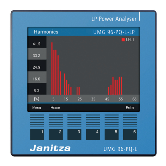
Page 100: Harmonics Menu
UMG 96-PQ-L-LP www.janitza.com 14.8 Harmonics menu Voltage L1, L2, L3 Current L1, L2, L3 Harmonics Voltage Currents Display of harmonics up to the 65th Display of harmonics up to the 65th harmonic. (Voltage L1, L2, L3) harmonic. (Current L1, L2, L3) INFORMATION Further menu items are available with module 96-PA-RCM-EL. -
Page 101: Events Menu
UMG 96-PQ-L-LP 14.10 Events menu All events Events Voltage U MAX U MIN U OFF Current I MAX External List of all events in the three-phase 4-wire Sequence of undervoltage in three-phase Dig. In. system 4-wire system Modbus Comparator All events... - Page 102 UMG 96-PQ-L-LP www.janitza.com Voltage interruption U OFF List of voltage interruptions Sequence of a voltage interruption Overcurrent I MAX List of all overcurrent events Sequence of an overcurrent event External > Digital input List of external events via digital inputs Sequence of an event at a digital input External >...
-
Page 103: System Info Menu
UMG 96-PQ-L-LP 14.11 System Info menu RS-485 communication System info Com. RS485 Peripheral Comparator groups Info base device Received (RX), sent (TX) and faulty data packets, RS-485 mode, device address, baud rate and timeout Peripherals INFORMATION Further menu items are avail-... -
Page 104: Configuration Menu - Password Entry
UMG 96-PQ-L-LP www.janitza.com 14.12 Configuration menu – Password entry The configuration of the measurement device can If a password is set, you must enter it to view or be protected with a password (the default setting change the device configuration. is 00000, i.e. no password). -
Page 105: Configuration Menu - Without Password/After Password Entry
UMG 96-PQ-L-LP 14.13 Configuration menu – without password/after password entry For information on the entries in the Summary Configuration menu, see section”12. Voltage Configuration” on p. 44. Current Power Energy Consumption overview Drag Pointer Harmonics Oszilloscope Events System info Configuration... - Page 106 UMG 96-PQ-L-LP www.janitza.com Display Settings for brightness, standby time after and brightness (standby) Settings for automatic return to the start screen Settings for the display colors of voltage and current (L1, L2, L3) System Firmware version and serial number. Resetting of energy measured values, Setting the time and password min.
- Page 107 UMG 96-PQ-L-LP Modbus editor Display Modbus register (address, value) and set values...
-
Page 108: Service And Maintenance
UMG 96-PQ-L-LP www.janitza.com 15. Service and maintenance Prior to outbound delivery, the device is subjected 15.3 Service to various safety tests and is marked with a seal. For questions not answered or described in this If a device is opened, the safety tests must be re- manual, please contact the manufacturer. -
Page 109: Clock/Battery
UMG 96-PQ-L-LP 15.6 Clock/Battery The supply voltage supplies the internal clock of the measurement device. If the supply voltage fails, the battery takes over the supply of voltage to the clock. The clock provides date and time information, for example for recordings and min. -
Page 110: Procedure In The Event Of A Malfunction
UMG 96-PQ-L-LP www.janitza.com 16. Procedure in the event of a malfunction Failure mode Cause Remedy No display External fuse for the supply voltage has Replace fuse. tripped. No current display. No measured voltage connected. Connect measured voltage. No measured current connected. -
Page 111: Technical Data
UMG 96-PQ-L-LP 17. Technical data General Net weight (with attached plug-in connectors) approx. 250 g (0.55 lbs) Package weight (incl. accessories) approx. 500 g (1.1 lbs) Battery Type Lithium CR2032, 3 V, (UL 1642 approved) Data memory 64 MB Backlight service life 40000 h (backlight reduces to approx. 50% over this period) - Page 112 UMG 96-PQ-L-LP www.janitza.com Voltage measurement Three-phase 4-conductor systems with rated voltages up to 417 V / 720 V (+-10%) according to IEC 347 V / 600 V (+-10%) according to UL Three-phase 3-conductor systems with rated voltages up to 600 V (+10%)
- Page 113 UMG 96-PQ-L-LP Analog outputs External power supply max. 33 V Current 0 .. 20 mA Update time Load max. 300 Ω Resolution 10 bit Connection capacity of the terminals (supply voltage) Connectible conductors. Only connect one conductor per terminal point! Single core, multi-core, fine-stranded 0.2 - 4.0 mm...
-
Page 114: Performance Characteristics Of Functions
The accuracy classes refer to the measuring inputs of the device. Upstream transformers can influence the accuracy. For low-power current transformers, we recommend using at least 10 A primary current and a maximum cable length of 5 m. Suitable current transformers can be found in our catalog or at www.janitza.com. -
Page 115: Modbus Addresses Of Frequently Used Measured Values
UMG 96-PQ-L-LP 17.2 Modbus addresses of frequently used measured values Address Format RD/WR Variable Unit Comment 19000 float _ULN[0] Voltage L1-N 19002 float _ULN[1] Voltage L2-N 19004 float _ULN[2] Voltage L3-N 19006 float _ULL[0] Voltage L1-L2 19008 float _ULL[1] Voltage L2-L3... -
Page 116: Number Formats
UMG 96-PQ-L-LP www.janitza.com Address Format RD/WR Variable Unit Comment 19100 float _IQH_SUML13 varh Reactive energy L1..L3, ind. 19102 float _CQH[0] varh Reactive energy, capacitive, L1 19104 float _CQH[1] varh Reactive energy, capacitive, L2 19106 float _CQH[2] varh Reactive energy, capacitive, L3... -
Page 117: Dimensional Drawings
UMG 96-PQ-L-LP 17.5 Dimensional drawings · The figures are for illustration purposes only and are not to scale. 96 mm 3.78 in Battery 96 mm 3.78 in Fig. Front view 1) Bottom view +0,8 3.62 +0.03 87,2 mm 6 mm 3.43 in... -
Page 118: Connection Example
17.6 Connection example - S1 Data GND 15 16 Digital inputs Digital outputs Analog RS-485 output UMG 96-PQ-L-LP Supply voltage Voltage measurement Current measurement 11 12 13 37 38 39 40 41 42 43 44 PE/FE 230V/400V 50Hz 1) UL/IEC approved overcurrent protective device... - Page 119 UMG 96-PQ-L-LP...
- Page 120 Vor dem Polstück 6 | 35633 Lahnau Germany Tel.: +49 6441 - 9642-0 info@janitza.com | www.janitza.com Doc. no. 2.061.120.1.a | 10/2023 | Subject to technical alterations. The latest version of the document can be found in the download area at www.janitza.com.
Need help?
Do you have a question about the UMG 96-PQ-L-LP and is the answer not in the manual?
Questions and answers