
Related Manuals for Jntech JNS Series


Summary of Contents for Jntech JNS Series
- Page 1 JNS Series Single Phase Energy Storage Inverter User’s Manual V1.0 (2017.12) Hefei Jntech New Energy Co.,Ltd...
-
Page 2: Table Of Contents
Indexes 1 Product Introduction……………………………………………….………2 2 Security statement and warning…………………………………………2 2.1Symbolic interpretation……………………………………………….3 2.2 Security statement……………….…………………...……………….3 3 Mechanical installation instructions……………………………………4 3.1 Packing list…………………………………..…………………………4 3.2 Machine appearance……………………………….…………………5 3.3 Installation position description……………………………...….…5 3.4 Installation of inverters………………………………………….……6 4 Electrical connection instructions………………………………………7 4.1 System electrical connection…………………………….………….7 4.2 Battery connection……………………………………………….……8 4.3 PV array connection…………………………………..………………9 4.4 AC connection ………………………………………………………10... -
Page 3: Product Introduction
1 Product Introduction Jntech JNS series inverter is solar energy storage inverter, which is used for solar energy storage system. When sunshine is sufficient, the inverter supply power which is generated by solar system to home load priority; when full sun light, less home load, inverter store redundant energy in battery ,when less sun or peak home load, battery release power to home load to reduce the pressure of state grid;... -
Page 4: Symbolic Interpretation
inverters and other equipment , during operation and maintenance, we must strictly observe all the following safety information hints, such as danger, warning and attention. Before using the product, please read all the labels and warning signs on this machine and this manual. -
Page 5: Mechanical Installation Instructions
To ensure that the DC input voltage is less than the maximum input voltage of the inverter, otherwise it will damage the inverter, which Jntech won’t bear the responsibility and quality assurance. ... -
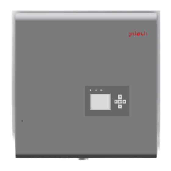
Page 6: Machine Appearance
3.2 Machine appearance 3.3 Installation site requirements: Please install the machine on the firm surface, and can support the weight of the inverter for a long time. Good ventilation on the installation location, can support the weight of the inverter for a long time ... -
Page 7: Installation Of Inverters
Installation of inverter should be far away from strong electromagnetic interference equipment, and away from flammable and explosive materials Inverter is recommended to install indoors. When the inverter is installed outside, it should be installed under the eaves or other shadowy areas to avoid direct sunlight, direct rain and snow. -
Page 8: Electrical Connection Instructions
Figure 3.4-1 Mounting hole Figure 3.4-2 Detail 4 Electrical connection instructions All electrical installations must conform to the local electrical installation standards All operation and wiring work is required by the professional staff Incorrect wiring operation may result in injuries and deaths of staff or or permanent damage to the equipment. -
Page 9: Battery Connection
Graph 4.1-1 system electrical connection diagram Note: the diagram shows that all over current protection devices are not included. The battery is a lead-acid battery or a lithium battery 4.2 Battery connection Please connect 1 DC breakers with rated current of 125A or over 125A between the battery and inverter. -
Page 10: Pv Array Connection
(1) Confirm that the battery meets the inverter specifications ensure that the DC circuit breaker is disconnected. (2) Unscrew the battery nut, put the cable passes through the nut hole, a sealed ring, an insulating ring, end out from the nut. (3)... -
Page 11: Ac Connection
Figure 4.3-1Schematic diagram of PV connector connection 4.4 AC connection For safe operation, AC circuit breaker shall be connected between inverter and power grid, inverter output and load appliance. The recommended specification is 250V/30A. The inverter output is not directly connected to any electrical appliance or power grid. -
Page 12: Communication Interface
(2) Unscrew the nut of the AC cover, open the sealing ring and transfer the cable through the nut hole, the sealing ring and the insulator successively, as shown in figure 4.3-1; (3) Insert the bare wire into the AC terminal and press it with the tool, such as figure 4.3-2 (4)... - Page 13 1. Meter communication connection An electric energy meter is connected between the AC breaker and the inverter (connection diagram shown in the next section), in which the communication connection between the energy meter and the inverter is shown as below: Figure 4.5-2 Meter Communication Attn:when the ammeter is connected correctly, the LCD screen will have corresponding hints when it is in normal communication, as shown in section 5.2.
-
Page 14: Trial Run
Attn: In the lower right corner of the display interface has a EMS communication identification, when the display is normal, black background and white "B", representing the meter communication connection abnormal, please check the EMS communication terminal; when the display is black letter and white background, it shows that the lithium battery and inverter communication is normal. -
Page 15: Trial Run Of Inverter
5.2 Inverter test operation 1. Make sure the above inspection items to meet the requirements. 2. Closed AC circuit breaker 3.Turn the DC switch at the bottom of the inverter to "ON". If the sunshine is sufficient and the grid conditions meet the requirements of grid connection, the inverter will enter the running state and convert the PV’s DC to the AC power,to feed into the power grid. -
Page 16: Operating Instructions
LCD screen is mainly divided into three parts, respectively, the main screen display part, status indicator light and keyboard part, as shown in figure 5.1-1: Figure 6.1-1 LCD panel 6.2 Operating instructions 1. The main interface displays the following contents: Figure 6.2-1 main screen display Attn:There is a normal communication mark in the lower right corner of a display meter, when displayed as black and white "kWh", representing the meter... - Page 17 view the sub menu content; each menu to switch between the press "confirm" button and the "back" button; " Use the "up", "down" and "confirm" keys to select and enter items within the menu. The menu: General set, battery set and advanced set of submenue are shown in below diagram: 3.
-
Page 18: Lcd Program Upgrade
The following example will show the specific practice of LCD operation, for other settings can refer to this case. For example: Set system time by menu,from "main menu", "setting", "general setting" to"system time". Main Interface Primary Menu Password dialogue box for menu setting up The password is defaulted,press “yes”to enter the setting up menu, press the "down"... -
Page 19: Working Mode Specification
As described in section 4.4, the inverter provides an USB interface that is only used to upgrade the LCD program. To upgrade the probram, according to the liquid crystal process described in the previous section, find the LCD program upgrade page, insert the storage device with new program, move the cursor to the "LCD Upgrade"... -
Page 20: Product Technical Parameters
Mode 4:State grid can also charge the battery. 8 Product technical parameters Mode JNS3KTL JNS5KTL PV parameter max power 3300W 5500W max input voltage 520 Vdc 125~450 Vdc MPP voltage range Full load operating 150~450 Vdc 230~450 Vdc voltage range 22A(11A/11A)... - Page 21 rate >0.99@ rated power(-0.9~+0.9, Adjusted) Power factor Max grid efficiency 97.4% 97.6% AC output parameter(off-grid) Rated power 2500W Rated output voltage 230Vac±5% Rated output 50Hz/60Hz±0.2%(optional) frequency Max current Total voltage <3%(rated power) waveform distortion rate 1.1 rated power@3min,1.25 @70s1.25 times Peak power rated power @70s Other parameters...
-
Page 22: Maintenance
9 Maintenance Before the inverter is maintained, it is necessary to ensure that the inverter is not charged. Once every six months, the following routine checks are carried out on the inverter. ● Observe whether the inverter is damaged or deformed. ●... -
Page 23: Attached Fault Code
2.If the fault exists all the 1-100 busbar ing. After the failure is time, contact the Hefei overvoltage eliminated, the battery Jntech customer service will run automatically center. 1.Measure the overvoltage of the battery voltage. The battery stops charg- 2.Waiting for the inverter to ing and discharging. - Page 24 2.If the fault exists all the 1-111 Down to 50% operation sensor of the DC time, contact the Hefei module radiator Jntech customer service center. The battery stops charg- 1.Restart the inverter. ing and discharging. After 2.If the fault exists all the...
- Page 25 4. If the fault exists all the after the fault is elimi- amplitude under time, contact the Hefei nated. 2-114 voltage of state Jntech customer service grid center. Unfinished phase 2-115 lock of state grid 1.Restart the inverter. DC AC Module sampl- 2.If the fault exists all the...
- Page 26 3.If the restart of the operated automatically DC component after fault inverter is invalid, please Overlimit of B eliminated contact the Hefei Jntech 2-213 phase current on gathering customer DC component service center. Failure of leakage 1.Check whether the grid...
- Page 27 requirements inverter. Check whether the current configuration of the Array 2 DC hard The PV module operates 3-102 second PV array meets the overcurrent the current limit. requirements of the inverter. 1.Check the LCD screen to The PV module stops show whether the PV radiator working.
Need help?
Do you have a question about the JNS Series and is the answer not in the manual?
Questions and answers