Table of Contents
Advertisement
Advertisement
Table of Contents

Subscribe to Our Youtube Channel
Related Manuals for Jntech JNP75KH


Summary of Contents for Jntech JNP75KH
- Page 1 Solar Pumping Inverter User Manual JNP75KH JNP90KH JNP110KH JNP132KH...
- Page 2 The copyright belong to Supplier. This document involves the proprietary and confidential information about Solar pumping inverter of Supplier. It strictly prohibited to disclose the document by duplicating, photocopying, publishing online and in other forms without the company’s permission. Supplier. reserves the right to change details in this publication without notice.
-
Page 3: Preface
● JNP132KH ● In order to describe conveniently later, JNP75KH, JNP90KH, JNP110KH, JNP132KH will be short for JNPxH, solar pumping inverter will be short for inverter. The inverter type shall be pointed alone, when introduce the information about each type of inverter in details. - Page 4 Safety Meaning Symbol Means that it may lead to serious accident of injuries, if safety warning is ignored. Danger! Means that it may lead to serious accident of injuries, equipment serious damage or main business interruption, if Warning! safety warning is ignored. Means that it may lead to moderate accident of injuries, equipment moderate damage or part of the business Notice!
- Page 5 Should wait for 5 minutes after inverter and PV panel are disconnected, then inverter only can be touched. Beware of hot surface The inverter temperature can exceed 60℃ during operation. Please don’t touch the surface to avoid scald. CE certification marks. It means that inverter complies with the requirement of CE certification.
-
Page 6: Table Of Contents
CONTENT PREFACE ....................II ..................II ANUAL NSTRUCTION ..................... II ARGET EADER ..................II SE THE ANUAL ....................II YMBOL 1 SAFETY INSTRUCTIONS ................1 2 PRODUCTION INTRODUCTION..............6 2.1 S ............6 OLAR PUMPING YSTEM NTRODUCTION 2.2 P ............... 7 RODUCTION NTRODUCTION 2.2.1 Production Appearance .............. - Page 7 5.2 I ................16 NSTALLATION IRECTION 6 ELECTRICAL CONNECTION..............18 6.1 S .......... 19 CHEMATIC DIAGRAM OF ELECTRICAL CONNECTION 6.2 I ................20 NVERTER TERMINALS 6.3 C ..........21 ABLE ELECTION FOR LECTRICAL ONNECTION 6.4 DC S ................21 ONNECTION 6.5 AC S ..............
- Page 8 8.1 I LCD D ................39 NVERTER ISPLAY 8.1.1 LED Indicator Direction ..............39 8.1.2 Description of Buttons ..............40 8.1.3 LCD Display Interface Overview ............. 41 8.2 I ..............42 NITIAL PERATIONAL NTERFACE 8.3 M ..................44 8.3.1 Operation Information ..............45 8.3.2 Basic Information .................
-
Page 9: Safety Instructions
1 Safety Instructions For the electrical and electronics equipment, safety relates to the whole process of installation, commissioning, operation and maintenance. Therefore, incorrect use or operation would damage the life and personal security of operating person or the third party, and inverters. In order to reduce casualties, damage of inverter and other equipments, user or operating person should strictly abide by all the safety information tips of danger, warning and note which are in the process of operating and maintaining. - Page 10 Installing Ensure inverter not have electrical connections and electricity before installing. Danger! The solar cell arrays should be covered with opaque materials when installing the photovoltaic arrays during the day, otherwise the solar cell arrays will generate high voltage, causing person casualties.
- Page 11 Warning! If inverter damage caused by the following circumstances will be beyond the warranty scope of our company. Ensure that the max. short-circuit of DC side is in the inverter allowable range ● when configuring PV arrays, otherwise, inverter may be caused non-recoverable damage.
- Page 12 Warning! All the operation and wiring work should be operated by professional electrical ● or machine engineer. Please do not close any breakers before all the equipments are not fully ● connected well. Notice! All the electrical installation must meet the electrical installation standard of ●...
- Page 13 Notice! Only LCD display screen and DC switches can be touched when the inverter is running, the heating devices (such as radiator, etc.) should not be touched to avoid scald. Maintenance Danger! Maintenance should be done by professional maintenance technical person. ●...
-
Page 14: Production Introduction
2 Production Introduction 2.1 Solar pumping System Introduction Solar pumping system is different from traditional AC pump application system, Solar pumping system is using solar cells to directly convert solar energy into electrical energy, then Solar pumping inverter drive the AC motor to drive pump getting water from deep well, river, lake etc., finally transport to the destination to meet our demand for water. -
Page 15: Production Introduction
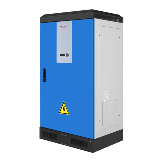
Table2-1 Solar pumping application system list Name Description PV array Monocrystalline silicon, Polycrystalline silicon Solar pumping JNP75KH,JNP30KH,JNP37KH,JNP45KH,JNP55KH. inverter AC pump Three-phase AC pump. Water storage Can be the reservoir, fields etc. device 2.2 Production Introduction 2.2.1 Production Appearance Figure2-2 Appearance of Solar pumping inverter... -
Page 16: Production Dimensions
Table2-2 Inverter appearance information table Name Introductions LCD display Man-machine interface, you can check the inverter screen operating information through LCD display screen, also can set some parameters of inverter. Handle Front door handle Input Wire casing Including DC input terminals(PV+/PV-) Output wire casing Including output(U、... -
Page 17: Product Name
JNP75KH 1210 JNP90KH 1210 JNP110KH 1210 JNP132KH 1210 2.2.3 Product Name The way of product naming, take JNP75KH for example: 75K H H: 380V Company name Product series name Power level 2.3 Technical Feature Advanced IGBT power module; ● MPPT(Maximum... -
Page 18: Inverter Unpacking
3 Inverter Unpacking 3.1 Unpacking Check The product has been tested and checked carefully before transportation, but damage may be caused during transportation, therefore, the product should also be checked carefully before installation. Please check whether inverter outer packing is in good condition; ●... -
Page 19: Identify Inverter
Table3-1 Inverter and fittings table Description Status PV pump inverter Standard User manual Standard Water level sensor B Optional Water level sensor A Optional Certificate of inspection Standard Pressure sensor Optional Packing List Standard 3.2 Identify Inverter The nameplate in the side of inverter, and it shows the inverter model, main parameter and certificate mark. - Page 20 Table3-2 Nameplate information table Description Company Logo and name. Inverter model and parameter information. Certificate and safety signs, concrete meaning as “Preface”. Company and address. Inverter factory number. Note! Photos are for reference only, Please adhere to the original products!
-
Page 21: Installation Procedure
4 Installation Procedure 4.1 Prepare Installation Tools Inverter installation and wire installation will need the following tools. You also can choose the right tools according to your own experi ence Table4-1 Installation tools list Sketch map Name Recommend Function specification Straight Used for the AC wire Ф3... - Page 22 Table4-2 Installation process Installation Installation instruction steps Reference chapters Before installation, check whether the inverter is in good condition or not; Whether the product fittings are complete Whether the installation tools and spare parts are complete Whether the installation environment meets the requirements Read the manual, especially the "Safety Instructions”...
-
Page 23: Installation
5 Installation 5.1 Installation Site Required Inverter installation site environment has very important influence to the safe operation, the performance and life of the inverter. Choose the right installation site before install the inverter. Figure5-1 Installation Direction All installation must comply with local standards. ●... -
Page 24: Installation Direction
inverter is installed outdoor, should be installed as far as possible in the eaves or other have the shadow place, avoiding direct sunlight, rain and snow. Inverter is installed indoor, keep away from windows, avoiding lightning ● The installation place selected should be solid enough to support the inverter ●... - Page 25 Figure5-2 Minimum spacing of adjacent installations Table5-1 Minimum spacing dimension Direction Minimum spacing 100cm 100cm 100cm 100cm 100cm...
-
Page 26: Electrical Connection
6 Electrical Connection The electrical connection can be carried out when the mechanical installation of inverter is completed. The following operation specification must be followed when making electrical connection. Warning! All the electrical connection must meet local electrical connection ● standard. -
Page 27: Schematic Diagram Of Electrical Connection
6.1 Schematic diagram of electrical connection Figure6-1 External connection terminals of inverter Table6-1 Terminals Description Items Description PV Array Max. open voltage of each string is 880Vdc Non-standard accessory Can be ordered PV combiner box from SUPPLIER. PV pump inverter Main device of system Pump Three phase AC pump... -
Page 28: Inverter Terminals
6.2 Inverter terminals Input and Output terminals are at the bottom of inverter. As shown in following figure. Figure6-1 Electrical connection terminal Table6-1 Mark for connection terminals Terminal Description PV + PV positive input terminals PV - PV negative input terminals U/V/W AC output terminals, connect with AC pump... -
Page 29: Cable Selection For Electrical Connection
6.3 Cable Selection for Electrical Connection Please select cable according to the following table. Table 6-3 Specification of Cables for Electrical Connection Inverter Conduct cable recommendation(mm²) model DC side AC side PV+、PV- U、V、W JNP75KH 70mm 70mm 35mm JNP90KH 95mm 95mm 35mm JNP110KH 120mm... - Page 30 Note! make sure PV arrays are same, including the model of PV module, number, ● angle, azimuth, and connecting wires being with the same cross-sectional area. Inspect every system carefully before installation. ● Step1: Please connect the wire of the DC connector according to the following Step2: Ensure that the DC-side PV combine box are in off state.
-
Page 31: Ac Side Electrical Connection
Warning! Make sure the Positive & Negative poles connection of PV array and Inverter are correct! 6.5 AC Side Electrical Connection Notice! It’s forbidden to connect several inverters in parallel to one set of pump! Danger! Ensure that all cables are not charged before electrical operation! Step1: Wire connection of the connector: Please connect the wire of AC connector according to the following figure:... -
Page 32: Water Level Sensor Connection
Step2: AC cables connect with three phase terminals of pump, inverter earth wire connect with pump earth wire terminal. 6.6 Water Level Sensor Connection Dry protection function: There have two kinds of detection models, automatic and manual. Automatic dry protection is achieved through inverter ’s software. And manual model need water level sensors to input signal through SENSOR inside Supplier Inverter. -
Page 33: Water Level Sensor Interface Define
6.6.1 Water level sensor interface define Water level sensor connector pins in inverter panel port are defined are shown below: DG_IN SY_IN Figure 6-5 water level sensor connector terminals Table6-4 the definition of pin of terminal block Pin NO. Description +24VDC Positive of 24V DC power. -
Page 34: Water Level Sensor Connection
Positive of VCC. Negative of VCC. P_IN Input of pressure signal. DG_IN Dry protection signal input terminal of sensor SY_IN Overflow protection signal input terminal of sensor Common terminal of water level sensor SW_IN Input of switch signal. SW_OUT Output of switch signal. Negative of switch signal. - Page 35 If you selected water level sensor A, then water sensor installation method is shown below: Figure6-7 The detail figure of Sensor A...
-
Page 36: Communication Connection
Figure6-8 The installation figure of Sensor A If you selected water level sensor B, then water sensor installation method is shown below: Figure6-9 The installation figure of Sensor B Notice! If you choose Water Level Sensor B, please note the following aspects when intall: 1. - Page 37 connector can be used for communication connection between inverter and monitor equipment. The COM terminal outside is for remote communication, output cable connect into monitoring PC. please refer to table 6-4 for COM terminals with inverter weak current signal connection terminals instruction. The following diagram guides you to connect a single inverter to monitoring equipment.
-
Page 38: Gprs Communication
Note! The monitoring software is optional, when choose this function, “Inverter Management System User Manual” can be found from the accompanying CD. The inverter is supplied with default address "10". 6.7.2 GPRS Communication Note:More information about the communication module, please refer to the User and Installation Manual for GPRS. -
Page 39: Commissioning
7 Commissioning 7.1 Verify before Commissioning PV Arrays The PV array should be checked before operating the inverter, and to ensure that the positive and negative mustn’t be misconnect, otherwise, the damage may be caused to the inverter. Make sure that the open-circuit voltage of photovoltaic array doesn’t exceed the required voltage. -
Page 40: Modify Motor Parameters
Rated rotate speed Rated Rated Power Model Power Frequency Surface Submersible volt. current factor pump pump 380V 142A 50Hz 1475 2875 JNP75KH 75KW 0.86 60Hz 1770 3450 380V 171A 50Hz 1475 2875 JNP90KH 90KW 0.86 60Hz 1770 3450 380V 209A... -
Page 41: Motor Parameters Detection And Commissioning
7.4 Motor parameters’ detection and commissioning 7.4.1 Motor parameters’ detection 7.4.1.1 Motor parameters’ detection After finishing the modification, press “ENTER” & “DOWN” at the same time to return to the first screen, long-press “ON/OFF” for 4S, and inverter begin motor parameters’ detection, if success, it will indicate “Test finish Start up? YES/NO”;... -
Page 42: Commission
7.4.1.2 Set motor parameters by manual If the first commission failed caused by motor parameters’ mismatching, and reset by manual is required. Please refer to the following steps: Stop Inverter; Refer to “8.3.5.3 Key Parameters of the System Set ” to change “MP-Sel” to “manual”;... - Page 43 Figure 7-2 Inverter start to operation inverter Note! If there is no water output , or flow rate is less than normal situation, even ● there has abnormal sound of pump, possible reasons are shown below: a) Pump motor reversal caused by wrong phase sequence connection. Stop inverter, enter into “M-Mode”...
- Page 44 7.4.2.2 Motor parameters’ setting by manual If inverter alarm malfunction and cannot pump water caused by mismatching parameters during the first commissioning, setting motor parameters by manual is required. First step: Stop inverter; Second step: refer to “8.3.5.3 Key Parameters of the System Set ” to change “MP-Sel”...
-
Page 45: Inverter Operation Mode Switch
7.5 Inverter Operation Mode Switch There are two kinds of operation mode of Inverter, one is Vector Control as default, and the other one is VF Control. If you want to try VF, or the performance of Vector is not good, please refer to the following step: First: Stop inverter, and ensure it’s standby;... -
Page 46: Time Calibration
Note! The set of “StopFreq” can ensure inverter stop working when the output power of PV array is too weak to pump water, which can increase the pump’s lifespan. 7.8 Time Calibration The initial time in the inverter is based on Beijing time zone. Please reset time if it doesn't match local time so that the inverter can re cord daily, total generating capacity and historical faults information. -
Page 47: Lcd Panel Operating Instructions
8 LCD Panel Operating Instructions 8.1 Inverter LCD Display There have three LED lights, four buttons on the LCD Display, shown in figure 8-1. Figure8-1 LCD Display 8.1.1 LED Indicator Direction Table8-1 LED Indicator Direction Name Color Instructions Indicator POWER Power light Green Light on When power on... -
Page 48: Description Of Buttons
8.1.2 Description of Buttons Table8-2 Buttons Function Table Buttons Name Functions Press once to stop; long time press for “ON/OFF” 4s to get it started. “UP” Page up and increase data. “DOWN” Page down and decrease data. “ENTER” To choose and confirm. “DOWN+ENTER”... -
Page 49: Lcd Display Interface Overview
8.1.3 LCD Display Interface Overview RunInfo Time Year Month Date Hour Fout Start Minute Iaout Temp ErrCode Initialize T-Limit T-Value Waiting... StopCode S-Mode Para Set U-Rated Run Waiting D-Mode I-Rated P-Rated OF-F F-Rated Run/Stop RPM-Rated PF-Rated LCD-Ver Imotor StopFreq DSP-Ver R-Mode M-Mode SiteNum... -
Page 50: Initial Operational Interface
8.2 Initial Operational Interface Once the inverter power on, the system start to initialize, display the initialization interface: Figure8-3 System initialize If the start-stop mode is auto., countdown interface will be display after initialization complete, and when countdown finished, LCD will enter the main interface, inverter will drive water pump. - Page 51 inverter can stop auto. Please refer to “8.3.5.2 Timing Shutdown Time Set” for timing shutdown setting. After inverter initializing, main interfaces will be displayed circularly: Figure8-5 Main interface Main interface display basic running information. Main interface will turn page auto after 10s, or you can turn page through pressing "UP" and "DOWN" button.
-
Page 52: Main Menu
Dry mode of PV pump system: “AUTOMATIC” doesn’t need D-Mode external water level sensor, “DETECTION” need external water level sensor. The optional function of overflow alarm in PV pump system . On: Inverter has over-flow protection function, If user's solar pump system include water storage device, this parameter should be set to "ON". -
Page 53: Operation Information
8.3.1 Operation Information RunInfo, display the running information of the inverter, please refer to the figure below. R-Mode MPPT RunInfo RunInfo RunInfo InverterInfo InverterInfo ENTER MotorCtrlPara ENTER MotorCtrlPara Iaout Statistic Statistic Fout 0.00Hz Settings Settings Run/Stop Stop Fault Inquiry Fault Inquiry D_Mode Auto OF-F... -
Page 54: Basic Information
ErrCode The most recently error mode. Stop code, can check the reason of inverter shut down most StopCode recently. S-Mode Start and stop mode. D-Mode Protection mode against well dry out. Water overflow alarm function optional in PV pump system OF-F storage device. -
Page 55: Motor Control Parameter Interface
LCD-Ver Version information of LCD program. DSP-Ver Version information of DSP program. Site number of network node of inverter, when communicate SiteNum with RS485. Default value is 10. If modifiable, please refer to“8.3.5.4Site Number Set”. Series number of inverter. Type of inverter. Current day, from left to right shows day, month and year. - Page 56 Figure8-8 Motor control parameter query step figure Table 8-7 Motor control parameter list Motor control Instructions parameter R-Stat Detected motor stator resistance L-Leak Detected motor leakage R-Rotr Detected motor rotor resistance L-Mutu Detected motor mutual inductance I-Ext Excitation current U-KP Proportional coefficient of voltage loop U-KI Voltage loop Integral coefficient...
-
Page 57: Statistic Interface
QIINST Q axis instruction current QIFACT Q axis actual current QUINST Q axis instruction voltage DIINST D axis instruction current DIFACT D axis actual current DUINST D axis instruction voltage ITORQUE Max. torque current Return to previous menu Note! The above parameters can only be read, cannot be revised. 8.3.4 Statistic Interface Statistic, statistic of the totally running time and power generation of inverter. -
Page 58: Parameter Setting
RunInfo RunInfo R-Mode MPPT RunInfo InverterInfo InverterInfo MotorCtrlPara ENTER UP/DOWN MotorCtrlPara Statistic Iaout Statistic Statistic Settings Fout 0.00Hz Settings Fault Inquiry Run/Stop Stop Fault Inquiry D_Mode Auto OF-F RunInfo InverterInfo MotorCtrlPara RunT_D 60min RunT_D 60min Statistic Statistic RunT_T RunT_T Settings ENTER E-Day 0kWh... - Page 59 RunInfo RunInfo RunInfo R-Mode MPPT InverterInfo InverterInfo ENTER MotorCtrlPara MotorCtrlPara UP/DOWN Statistic Statistic Iaout Settings Settings Settings Fout 0.00Hz Fault Inquiry Fault Inquiry Run/Stop Stop D_Mode Auto OF-F ENTER Password Password RunInfo InverterInfo MotorCtrlPara Statistic Settings Settings Fault Inquiry Password error Password Password Incorrect...
- Page 60 Table8-9 Inverter setting Settings Explain Time Adjust LCD display time. To set the stopping time according to user requirement, T-Limit inverter will stop running automatically as setting. For user to set the critical parameters of Solar pumping Para Set system. SiteNum Set Site number setting for remote communication.
- Page 61 Figure8-11 Procedure of display time set Note! Here just taking the “Year” setting as an example, the “Date” and “Time” setting are same as “Year”. Table8-10 Inverter time set Time Explain Year Adjust LCD display year Month Adjust LCD display month Date Adjust LCD display date Hour...
- Page 62 8.3.5.2 Timing Shutdown Time Set T-Limit, to set timing shutdown time of the inverter. Please refer to the figure below. Figure8-12 Procedure of timing set 8.3.5.3 Key Parameters of the System Set Para Set, to set the key parameters when your chosen pump is not matched to the rated power of Inverter.
- Page 63 Figure8-13 Procedure of key parameters reset Note! Just take “U-Rated” set as an example, other setting is the same.
- Page 64 Table8-11 Loading matching set Para Set Explain Motor rated voltage (V), which should be set according to pump U-Rated nameplate. Motor rated current (A), which should be set according to pump I-Rated nameplate. Motor rated power (w), which should be set according to pump P-Rated nameplate.
- Page 65 =3 VF control model; =5 Step by step motor parameter detection model; =6 Continuous motor parameter detection model; =8 Theoretical calculation PI parameter model. =0 full-order mathematic model; =1 voltage model; VC-Sel =2 improved voltage model; =3 improved full-order mathematic model. FL-Limit Flux linkage limit of motor.
- Page 66 For choose over flow warning function. Default is no overflow OF-F warning. If you want to use this function, please set to “on”. Default is “OFF”. OF-Time Over-flow alarming recovery time. =AUTO Motor parameter self-detection; MP-Sel =Manual Motor parameter input by manual. =1 Detect stator resistance;...
- Page 67 Notice! Those parameters cannot be changed easily, only when you get Supplier ● New Energy engineer’s recommendation. Supplier New Energy Inverter is not allowed to be used to drive the pump, ● which rated power is higher than its max. applicable motor output power. 8.3.5.4 Site Number Set SiteNum Set, for remote RS485 communication use.
- Page 68 8.3.5.5 Statistical Data Clear Clear S-Data, reset accumulated running duration and power inverted figure. Please refer to the figure below. Figure8-15 Produce of statistic data clear 8.3.5.6 Historical Malfunction Clear Clear F-Data, to clear historical malfunction record. Please refer to the figure below.
- Page 69 8.3.5.7 Password Set Password Set, to set the password to enter set menu, please refer to the figure below. Figure8-17 Procedure of password set 8.3.5.8 Language Set Language set, to set the man-machine interface language category, please refer to the following steps to operate.
-
Page 70: Fault Inquiry
Figure8-18 Procedure of language set 8.3.6 Fault Inquiry Fault Inquiry, to inquiry current and historic malfunction. Table8-13 Fault inquiry Fault Inquiry Explain Current Fault Current fault inquiry. History Fault History fault inquiry. Return to the previous menu. Current Fault, to enquire current malfunction, please refer to the figure below. -
Page 71: Malfunction Warning
Figure8-19 Procedure of the current fault inquiry 8.3.7 Malfunction Warning If communication failure appears, the below interface will appear. Figure8-20 Communication error screen This interface will appear, and Fault red led flickers to show malfunction, this means internal communication malfunction is appear. Figure8-21 Fault screen Display show malfunction, fault LED lights up, shows inverter malfunction or stop. - Page 72 Note! Malfunction manual reset function: when the machine breakdown with malfunction, can long press "ON/OFF" button, the machine can automatically restart immediately. When the machine is displayed Fault12, no such reset function. Fault code and the corresponding meaning are listed below Table8-12 Malfunction and condition code LCD showed Name of malfunction and condition...
-
Page 73: Malfunction And Troubleshooting
9 Malfunction and Troubleshooting 9.1 Troubleshooting Once malfunction or stop condition appears, the malfunction LED will lighten up, LCD will display current malfunction or stop condition, current malfunction will be recorded by the system for later inquire. Please refer to t he form below which covers the fault and troubleshooting. - Page 74 Please check the input Inverter shutdown voltage from array and make when fault Out put energy sure this voltage inside State 01 appeared and will from array inverter input voltage range. automatically restart changes Note: cloudy days, after it disappear morning, down, this...
- Page 75 Table9-3 Malfunction and troubleshooting Condition Phenomena Cause value Troubleshooting code Inverter shutdown Please check if there is short will restart Short circuit in circuit in output wires Fault00 automatically after output wire the fault disappears 1. Please make sure the system is proper designed.
- Page 76 Inverter shutdown Input current of If this happen, please contact will restart inverter higher Supplier. Fault07 automatically after than rated the fault disappears maximum value inspect 1. Power 1. Please whether capacity of pump motor is normal. inspect pump motor is 2.
-
Page 77: Maintenance
1. Please check if the output Inverter shutdown wires are proper connected will restart Phase loss Fault15 and fixed. automatically after inverter output 2. If this happen frequently, the fault disappears please contact Supplier. 9.2 Maintenance Please check and ensure the inverter is not charged with electricity before any maintenance. -
Page 78: Contact Customer Service
9.3 Contact Customer Service If you have any question about solar pumping inverter, please contact us, In order to provide faster and better service, please provide us with information below: Model of Inverter ● Series number of inverter ● Malfunction name and time ●... - Page 79 10 Appendix A Technical Data Item \ Model JNP75KH JNP90KH JNP110KH JNP132KH DC input Max. input DC 880Vdc 880Vdc 880Vdc 880Vdc voltage Recommended 460-850Vdc 460-850Vdc 460-850Vdc 460-850Vdc MPPT voltage Max. input DC 166A 205A 251A 287A current MPPT efficiency Number of string AC output Max.
- Page 80 System parameter Max. efficiency Protective class IP21 Protection degree Operating -25℃ to +50℃, above 50℃ need derate operating temperature range Cooling method Natural cooling Display Communication RS485/GPRS interface Altitude 3000m; above 3000m need derate operating <50dB Noise emission Compliance EN 50178; IEC/EN 62109-1; IEC 61800...
-
Page 81: Quality Assurance
11 Appendix B 11.1 Quality Assurance The product malfunction in the warranty period, Supplier will be free repair or replacement products. The warranty period take the contract as a standard. Evidence During the warranty period, customers should provide the invoices for the purchase of products and date. -
Page 82: Contact Us
If the product size and parameters have changed, the latest information given by the company shall prevail without notice. 11.2 Contact Us If you have any question about Solar pumping inverter, please contact us, and we will be happy to give you answers. Please remember the following contact information.
Need help?
Do you have a question about the JNP75KH and is the answer not in the manual?
Questions and answers