Table of Contents
Advertisement
Quick Links
Quick Installation
Solar pumping inverter
JNP550L-V5 JNP750L-V5 JNP1K1L-V5
JNP1K5L-V5 JNP2K2L-SE-V5 JNP2K2L-V5
JNP3KL-V5 JNP3K7L-V5
JNP2K2H-V5 JNP3KH-V5 JNP3K7H-V5 JNP4KH-V5
JNP5K5H-V5 JNP7K5H-V5
JNP11KH-V4 JNP15KH-V4 JNP18K5H-V4
JNP22KH-V5 JNP30KH-V5 JNP37KH-V5
JNP45KH-V5 JNP55KH-V5
用户手册
JNPxG-QI-EN-V1.1
Advertisement
Table of Contents

Related Manuals for Jntech JNP550L-V5


Summary of Contents for Jntech JNP550L-V5
- Page 1 Quick Installation Solar pumping inverter JNP550L-V5 JNP750L-V5 JNP1K1L-V5 JNP1K5L-V5 JNP2K2L-SE-V5 JNP2K2L-V5 JNP3KL-V5 JNP3K7L-V5 JNP2K2H-V5 JNP3KH-V5 JNP3K7H-V5 JNP4KH-V5 JNP5K5H-V5 JNP7K5H-V5 JNP11KH-V4 JNP15KH-V4 JNP18K5H-V4 JNP22KH-V5 JNP30KH-V5 JNP37KH-V5 JNP45KH-V5 JNP55KH-V5 用户手册 JNPxG-QI-EN-V1.1...
-
Page 2: Table Of Contents
CONTENT QUICK INSTALLATION GUIDELINE FOR SOLAR PUMPING INVERTER –JNP550L-V5 JNP750L-V5 JNP1K1L-V5 JNP1K5L-V5 JNP2K2L-SE-V5 ..................4 JNP2K2L-V5 JNP3KL-V5 JNP3K7L-V5 JNP4KL .......4 JNP2K2H-V5 JNP3KH-V5 JNP3K7H-V5 JNP4KH-V5 JNP5K5H-V5 JNP7K5H-V5 ...................4 ................... 4 NVERTER NPACKING ....................5 NSTALLATION 2.1 Prepare Installation Tools..............5 2.2 Installation Direction and spacing dimension ........5 2.3 Installation of Inverter............... - Page 3 6.1 Connecting Terminals of Inverter ............ 18 6.2 Cable Selection for Electrical Connection ........19 6.3 AC Side Electrical Connection ............19 6.4 DC Side Connection ................. 20 6.5 Inverter grounding ................21 6.6 Water Level Sensor Connection............21 6.7 Communication connection ............21 QUICK INSTALLATION GUIDELINE FOR SOLAR PUMPING INVERTER –...
- Page 4 11 A ..............43 PPENDIX ROUBLESHOOTING 11.1 Troubleshooting for JNP550L-V5~JNP18K5H-V4 ......43 11.2 Troubleshooting for JNP22KH-V5~JNP55KH-V5 ......45 · ·...
-
Page 5: Quick Installation Guideline For Solar Pumping
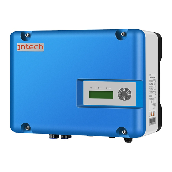
Quick Installation Guideline for solar pumping inverter –JNP550L-V5 JNP750L-V5 JNP1K1L-V5 JNP1K5L-V5 JNP2K2L-SE-V5 JNP2K2L-V5 JNP3KL-V5 JNP3K7L-V5 JNP4KL JNP2K2H-V5 JNP3KH-V5 JNP3K7H-V5 JNP4KH-V5 JNP5K5H-V5 JNP7K5H-V5 1 Inverter Unpacking Check according to Packing List whether all the parts are correct and in good condition or not. Accessories are shown as below:... -
Page 6: Installation
2 Installation 2 Installation 2.1 Prepare Installation Tools 2.1 Prepare Installation Tools The following tools will be needed in inverter installation and wire connection. The following tools will be needed in inverter installation and wire connection. Recommend Recommend Sketch map Sketch map Name Name... -
Page 7: Installation Of Inverter
2.3 Installation of Inverter Step1: Drill holes in the selected installation position according to the size ( Hole distance 210mm) . Step2: Fix inverter in the located holes with bolts. Step3: Tighten the bolts, make the bolts cling to the wall. ·... -
Page 8: Electrical Connection
3 Electrical Connection 3.1 Connecting Terminals of Inverter The input and output terminals are shown as below: Terminals Description Terminals Description PV array DC positive input terminals(PV+、PV-) · ·... -
Page 9: Cable Selection For Electrical Connection
RS485 or GPRS communication interface (VCC、A、B、GND) RS485 or GPRS communication interface (VCC、A、B、GND) (optional) (optional) Ground terminal Ground terminal Inverter model Inverter model Recommended parameters of DC circuit breaker Recommended parameters of DC circuit breaker JNP550L-V5 JNP550L-V5 440VDC,10A 440VDC,10A JNP750L-V5 JNP750L-V5 440VDC,10A 440VDC,10A JNP1K1L-V5 JNP1K1L-V5... -
Page 10: Ac Side(Ac In And Motor) Electrical Connection
JNP1K1L-V5 14-12 14-12 JNP1K5L-V5 14-12 14-12 JNP2K2L-V5 14-12 14-12 JNP3KL-V5 14-12 14-12 JNP3K7L-V5 14-12 14-12 JNP4KL-V5 12-10 14-12 JNP2K2H-V5 12-10 14-12 JNP3KH-V5 12-10 14-12 JNP3K7H-V5 12-10 14-12 JNP4KH-V5 12-10 14-12 JNP5K5H-V5 12-10 14-12 JNP7K5H-V5 12-10 14-12 3.3 AC Side(AC IN and MOTOR) Electrical Connection Step1: Please connect the AC wire according to the following steps: Operation Instruction Operation Demonstration... -
Page 11: Dc Side Connection
Note!The phase sequence of AC pump motor and inverter should be Note!The phase sequence of AC pump motor and inverter should be corresponding, and if connection error occurs, there will be no water output corresponding, and if connection error occurs, there will be no water output or only with small water flow. -
Page 12: Inverter Grounding
3.5 Inverter grounding 3.5 Inverter grounding Make sure the reliable connection between ground Make sure the reliable connection between ground terminal of Inverter terminal of Inverter and the earth! and the earth! 3.6 Water Level Sensor Connection 3.6 Water Level Sensor Connection 3.6.1 Water level sensor interface define 3.6.1 Water level sensor interface define Water level sensor connector pins in inverter panel port are defined are shown... - Page 13 Terminal(SENSOR) Detail connector pin Dry protection pin, Connected black cable Overflow protection pin, Connected white cable Dry protection and Overflow protection common pin, Connected green cable · ·...
- Page 14 3.6.2 Water level sensor connection 3.6.2 Water level sensor connection Two kinds of water level sensor you can select are shown below: Two kinds of water level sensor you can select are shown below: Sensor A Sensor A Sensor B Sensor B Notice!...
- Page 15 The installation figure of Sensor A If you selected water level sensor B, then water sensor installation method is shown below: For dry protection, the end with cable of sensor should be upwards connect white cable connect green cable A:the Installation location of overflow water level For over- sensor.
-
Page 16: Communication Connection
Notice! Notice! If you choose Water Level Sensor B, please note the following If you choose Water Level Sensor B, please note the following aspects when intall: aspects when intall: 1. For dry protection, the end with cable of sensor should be upwards; 1. -
Page 17: Quick Installation Guideline For Solar Pumping Inverter - Jnp11Kh-V4 Jnp15Kh-V4 Jnp18K5H-V4
Quick Installation Guideline for solar pumping inverter – JNP11KH-V4 JNP15KH-V4 JNP18K5H-V4 4 Inverter Unpacking Check according to Packing List whether all the parts are correct and in good condition. Accessories are shown as below: Description Description PV pump inverter Ring Terminals Installation bracket Packing list Blue Ring tool... -
Page 18: Installation
5 Installation 5 Installation 5.1 Prepare Installation Tools 5.1 Prepare Installation Tools Please refers to “2.1 Prepare Installation Tools”. Please refers to “2.1 Prepare Installation Tools”. 5.2 Installation Direction and spacing dimension 5.2 Installation Direction and spacing dimension Please refers to “2.2 Installation Direction and spacing dimension”. Please refers to “2.2 Installation Direction and spacing dimension”. -
Page 19: Electrical Connection
6 Electrical Connection 6 Electrical Connection 6.1 Connecting Terminals of Inverter 6.1 Connecting Terminals of Inverter The input and output terminals are shown as below: The input and output terminals are shown as below: Solar pumping inverter Solar pumping inverter Water Water pump... -
Page 20: Cable Selection For Electrical Connection
6.2 Cable Selection for Electrical Connection 6.2 Cable Selection for Electrical Connection User can select cables for electrical connection according to the following User can select cables for electrical connection according to the following specifications. specifications. Cable range(AWG) Cable range(AWG) Cable recommended(AWG)... -
Page 21: Dc Side Connection
6.4 DC Side Connection 6.4 DC Side Connection Danger!DC switch must be off, otherwise, it may cause casualty! Danger!DC switch must be off, otherwise, it may cause casualty! Step1: Please connect the DC wire according to the following steps: Step1: Please connect the DC wire according to the following steps: Operation Instruction Operation Instruction Operation Demonstration... -
Page 22: Inverter Grounding
6.5 Inverter grounding 6.5 Inverter grounding Make sure the reliable connection between ground Make sure the reliable connection between ground terminal of Inverter terminal of Inverter and the earth! and the earth! 6.6 Water Level Sensor Connection 6.6 Water Level Sensor Connection Water level sensor connector pins in inverter panel port are defined are shown Water level sensor connector pins in inverter panel port are defined are shown below:... - Page 23 Note:More information about the communication module, please refer to the User and Installation Manual. · ·...
-
Page 24: Quick Installation Guideline For Solar Pumping Inverter - Jnp22Kh-V5 Jnp30Kh-V5 Jnp37Kh-V5 Jnp45Kh-V5 Jnp55Kh-V5
Quick Installation Guideline for solar pumping inverter – JNP22KH-V5 JNP30KH-V5 JNP37KH-V5 JNP45KH-V5 JNP55KH-V5 7 Inverter Unpacking Check according to Packing List whether all the parts are correct and in good condition. Accessories are shown as below: Description Description PV pump inverter Quick Installation Guideline Installation bracket Packing list... -
Page 25: Installation
8 Installation 8 Installation 8.1 Prepare Installation Tools 8.1 Prepare Installation Tools Please refers to “2.1 Prepare Installation Tools”. Please refers to “2.1 Prepare Installation Tools”. 8.2 Installation Direction and spacing dimension 8.2 Installation Direction and spacing dimension Please refers to “2.2 Installation Direction and spacing dimension”. Please refers to “2.2 Installation Direction and spacing dimension”. -
Page 26: Electrical Connection
9 Electrical Connection 9 Electrical Connection 9.1 Connecting Terminals of Inverter 9.1 Connecting Terminals of Inverter The input and output terminals are shown as below: The input and output terminals are shown as below: Solar pumping inverter Solar pumping inverter PV array PV array PV combine box... -
Page 27: Cable Selection For Electrical Connection
9.2 Cable Selection for Electrical Connection User can select cables for electrical connection according to the following specifications. Cable range(AWG) Cable recommended(AWG) DC side AC side DC side AC side Inverter U、V、W U、V、W PV+、PV- PV+、PV- R、S、T R、S、T JNP22KH-V5 JNP30KH-V5 JNP37KH-V5 JNP45KH-V5 JNP55KH-V5 9.3 DC Side Connection... -
Page 28: Ac Side Electrical Connection
9.4 AC Side Electrical Connection Step1: Please connect the AC wire according to the following steps: Operation Instruction Operation Demonstration 2. Step Using wire crimpers, connecting PV cable and Cold-pressed Terminal(SC35-8). Step2: Fixed the AC cable( R、S、T、PE、U、V、W Secure to the terminal through the terminal cover ·... -
Page 29: Inverter Grounding
9.5 Inverter grounding 9.5 Inverter grounding Make sure the reliable connection between ground Make sure the reliable connection between ground terminal of Inverter terminal of Inverter and the earth! and the earth! 9.6 Water Level Sensor Connection 9.6 Water Level Sensor Connection 9.6.1 Water level sensor interface define 9.6.1 Water level sensor interface define Water level sensor connector pins in inverter panel port are defined are shown... - Page 30 9.6.2 Water level sensor connection 9.6.2 Water level sensor connection Two kinds of water level sensor you can select are shown below: Two kinds of water level sensor you can select are shown below: Sensor A Sensor A Sensor B Sensor B Notice!...
- Page 31 The installation figure of Sensor A If you selected water level sensor B, then water sensor installation method is shown below: The installation figure of Sensor B · ·...
-
Page 32: Communication Connection
Notice! Notice! If you choose Water Level Sensor B, please note the following If you choose Water Level Sensor B, please note the following aspects when install: aspects when install: 1. For dry protection, the end with cable of sensor should be upwards; 1. -
Page 33: Commissioning Guideline For Solar Pumping Inverter
Commissioning Guideline for solar pumping inverter 10 Commissioning 10.1 Verify before Commissioning PV Arrays The PV array should be checked before operating the inverter, and to ensure that the positive and negative mustn’t be misconnect, Make sure that the open-circuit voltage of photovoltaic array doesn’t exceed the required voltage. DC Input Make sure that the DC terminals of the inverter are connected correctly and maintained consistent with the PV array. -
Page 34: Lcd Panel Operating Instructions
10.2 LCD Panel Operating Instructions 10.2 LCD Panel Operating Instructions Inverter LCD Display Inverter LCD Display LED lights LED lights LCD display LCD display Buttons Buttons Name Name Color Color Instructions Instructions Indicator Indicator POWER POWER Power light Power light Green Green Light on When power on... -
Page 35: Commissioning For Jnp1K1L-V5~Jnp18K5H-V4
10.3 Commissioning for JNP1K1L-V5~JNP18K5H-V4 10.3 Commissioning for JNP1K1L-V5~JNP18K5H-V4 10.3.1 Only DC Input, Disconnect grid input 10.3.1 Only DC Input, Disconnect grid input Switch on inverter’s DC switch or DC side electric connection, inverter start Switch on inverter’s DC switch or DC side electric connection, inverter start initialization. - Page 36 R-Mode MPPT Pgrid RunInfo RunInfo RunInfo State_AC InverterInfo InverterInfo Iaout PumpInfo PumpInfo UP/DOWN ENTER ENTER Fout 0.00Hz After 3 secend Password Statistic Statistic Run/Stop Stop Settings Settings Settings D-Mode Auto Fault inquiry Fault inquiry OF-F Password Password Imotor 20.4A Error D-Power 1500W Time Time...
-
Page 37: Commissioning For Jnp22Kh-V5~Jnp55Kh-V5
frequency as following. Step 1: Ensure the system is running and there has water output, enter to ”StopFreq”. Step 2: To reduce the value of “StopFreq”. Reduce by 5Hz each time and press "ENTER" to check the system performance. Keep reducing the value till the water just can not come out. - Page 38 The inverter should set the motor parameters before operation, the parameters including rated voltage, rated current, rated power ,rated frequency, rated rotor speed and power factor. The motor nameplate parameters information should be related to the inverter parameters. Below take Siemens motor and inverter parameters as example. Table: motor nameplate as example Table: motor nameplate’s parameters contrast to inverter Motor parameters...
- Page 39 COSφ(P.F.) 0.86 PF-Rated 0.86 After confirming the needed parameters of inverter, enter the motor parameters interface of LCD displayed screen. The parameters should be the same as listed in table. The detailed operating processes are shown as below. · ·...
- Page 40 Password Password 时间设置 时间设置 Time Time Error Error T-Limit T-Limit 运行信息 运行信息 RunInfo RunInfo R-Mode R-Mode MPPT MPPT RunInfo RunInfo Para Set Para Set Inverterinfo Inverterinfo Inverterinfo Inverterinfo Password Password Pump Para Set Pump Para Set UP/DOWN UP/DOWN ENTER ENTER Is correct Is correct ENTER...
- Page 41 10.4.3 The test of motor parameters and commissioning 10.4.3 The test of motor parameters and commissioning After modify the motor parameters, long-press the “ON/OFF” button to enter After modify the motor parameters, long-press the “ON/OFF” button to enter into testing status of motor parameters, when test succeed, then press into testing status of motor parameters, when test succeed, then press “ENTER”...
- Page 42 processes are shown below: Password 时间设置 Time Error T-Limit 运行信息 R-Mode MPPT RunInfo RunInfo Para Set Password Inverterinfo Inverterinfo Pump Para Set UP/DOWN ENTER Is correct ENTER Pump Info ENTER Pump Info Password UP/DOWN Password Password SiteNum Set Statistic Statistic Iaout Clear S-Data ENTER...
- Page 43 Note: Note: If Solar Pumping System cannot pump water out and inverter If Solar Pumping System cannot pump water out and inverter display “state 09”, it may caused by air leak of pipe system, or long-time air display “state 09”, it may caused by air leak of pipe system, or long-time air discharge because of long pipe system.
- Page 44 At this point, congratulations! Your photovoltaic pumping systems first test running is completed! Thank you for using green energy, in order to improve our living environment contribution. 11 Appendix: Troubleshooting 11.1 Troubleshooting for JNP550L-V5~JNP18K5H-V4 Stop condition and troubleshooting Status Code Phenomena...
- Page 45 over-current automatically after 2. Hardware circuit situation between 3 the fault damage phase output wires disappears Please make sure the Inverter shutdown The capacity of load system is proper and will restart Fault105 is higher than rated designed. The power of automatically after Over-load output power of...
- Page 46 source cannot complement 1. Check the pump Inverter shutdown 1、Pump motor wiring and the pump for Fault202 and will restart locked-rotor, or normal operation; AC input automatically after damaged. 2. Check if the over-current the fault 2、hardware failure inverter output is disappears normal.
- Page 47 Please check PV input voltage and make sure Inverter shutdown the voltage is within State 101 and will Output energy from inverter input voltage PV Array automatically PV array is not range. under-voltage restart after it enough Note: In cloudy days, disappear morning and late in afternoon, this situation...
- Page 48 3. Pipe system design is not reasonable Fault111 Temp. sensor inside Please contact Temp. sensor Inverter shut down inverter loosen or supplier. fault damage Inverter shutdown, 1. Please check if there non-recover is short circuit in output Fault112 malfunction. No Output wire short wires.
- Page 49 low-voltage automatically after array voltage is too switch to ensure that the fault low or a hardware the inverter input has disappears. failure. no voltage. Check the grid voltage and PV voltage with a multimeter. One or two phase Disconnect the output cables of the grid and PV input Inverter shutdown...
Need help?
Do you have a question about the JNP550L-V5 and is the answer not in the manual?
Questions and answers