
Related Manuals for Jntech JNP1K1L-G


Summary of Contents for Jntech JNP1K1L-G
- Page 1 Solar Pumping Inverter User Manual JNP1K1L-G JNP1K5L-G JNP2K2L-G 用户手册 JNP2K2L-G-V3-EN-V3.0...
- Page 2 The copyright belong to Our company. This document involves the proprietary and confidential information about Solar pumping inverter of Our company. It strictly prohibited to disclose the document by duplicating, photocopying, publishing online and in other forms without Our permission.
-
Page 3: Preface
● JNP2K2L-G ● In order to describe conveniently later, JNP1K1L-G, JNP1K5L-G, JNP2K2L-G will be short for JNPxL-G, Solar pumping inverter will be short for inverter. The inverter type shall be pointed alone, when introduce the information about each type of inverter in details. - Page 4 Safety Symbol Meaning Means that it may lead to serious accident of injuries, if safety warning is ignored. Danger! Means that it may lead to serious accident of injuries, equipment serious damage or main business interruption, if Warning! safety warning is ignored. Means that it may lead to moderate accident of injuries, equipment moderate damage or part of the business Notice!
- Page 5 Should wait for 5 minutes after inverter and PV panel are disconnected, then inverter only can be touched. Beware of hot surface. The inverter temperature can exceed 60℃ during operation. Please don’t touch the surface to avoid scald. CE certification marks. It means that inverter complies with the requirement of CE certification.
-
Page 6: Table Of Contents
CONTENT PREFACE ....................III ................... III ANUAL NSTRUCTION .................... III ARGET EADER ..................III SE THE ANUAL ....................III YMBOL 1 SAFETY INSTRUCTIONS ................1 2 PRODUCTION INTRODUCTION..............6 2.1 S ............6 OLAR UMPING YSTEM NTRODUCTION 2.2 P ’ ................. - Page 7 5.2 I ................16 NSTALLATION IRECTION 5.3 I ................17 NSTALLATION OF NVERTER 6 ELECTRICAL CONNECTION...............19 6.1 C ............19 ONNECTING ERMINALS OF NVERTER 6.2 S ..........20 CHEMATIC IAGRAM OF LECTRICAL ONNECTION 6.3 C ................... 22 ABLE ELECTION 6.4 AC S ..............
- Page 8 8.1 I LCD D ................44 NVERTER ISPLAY 8.1.1 LED Indicator Direction ..............44 8.1.2 Description of Buttons ..............45 8.1.3 LCD Display Interface Overview ............. 46 8.2 I ..............49 NITIAL PERATIONAL NTERFACE 8.3 S ............50 YSTEM PARAMETER QUERY AND SETTING 8.3.1 Query information item description ..........
-
Page 9: Safety Instructions
1 Safety Instructions For the electrical and electronics equipment, safety relates to the whole process of installation, commissioning, operation and maintenance. Therefore, incorrect use or operation would damage the life and personal security of operating person or the third party, and inverters. In order to reduce casualties, damage of inverter and other equipments, user or operating person should strictly abide by all the safety information tips of danger, warning and notice which are in the process of operating and maintaining. - Page 10 Danger! The solar cell arrays should be covered with opaque materials when installing the photovoltaic arrays during the day, otherwise the solar cell arrays will generate high voltage ,causing person casualties. Electrical connections Danger! Ensure that the solar cell array should be covered by light tight materials, before electrical connecting, otherwise, the solar cell array would produce high voltage under the sun to cause casualties.
- Page 11 Warning! If inverter damage caused by the following circumstances will be beyond the warranty scope of our company. Ensure that the max short-circuit of DC side is in the inverter allowable range when ● configuring PV arrays, otherwise, inverter may be caused non-recoverable damage. Ensure that the open circuit voltage of JNPxL-G shall not exceed 450V when ●...
- Page 12 Notice! All the electrical installation must meet the electrical installation standard of local and ● country. In order to ensure safe running, proper grounding, using appropriate conductor size ● and providing short circuit protection are required. Connection cable must select suitable specification, firm connection and ●...
- Page 13 Maintenance Danger! Maintenance should be done by professional maintenance technical person. ● Please ensure that AC side breakers should be turned off firstly, then DC side ● breakers should be turned off before checking and maintaining, after waiting at least 5 minutes, should measure DC side and AC side voltage with a voltage meter, to ensure that operation under the circumstance of no voltage between DC side and AC side.
-
Page 14: Production Introduction
2 Production Introduction 2.1 Solar Pumping System Introduction Solar pumping system is different from traditional water pumping system, which takes use of solar cells to convert solar energy into electricity. It consists of 4 parts: PV modules, PV Pump Inverter, 3 phases AC pump and water storage device. - Page 15 Figure2-1 Solar pumping application system Table2-1 Solar pumping application system list Name Description PV array Monocrystalline silicon, Polycrystalline silicon. Solar pumping JNP1K1L-G, JNP1K5L-G, JNP2K2L-G. inverter AC pump Three-phase AC pump. Water storage Can be the reservoir, fields etc. device...
-
Page 16: Product's Introduction
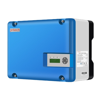
2.2 Product’s Introduction 2.2.1 Appearance Figure2-2 Appearance of Solar pumping inverter Table2-2 Inverter appearance information table Name Introductions LCD display Man-machine interface, you can check the inverter screen operating information through LCD display screen, also can set some function and parameters of inverter. Connection Including DC input terminal (PV1+/PV1-/PV2+/ terminals... -
Page 17: Production Dimensions
Used to hang the inverter on the bracket. 2.2.2 Production Dimensions Figure2-3 Dimension drawing of Solar pumping inverter (unit: mm) Table2-3 Inverter dimension table Net weight ( kg) Model Width(mm) Height(mm) Depth(mm) JNP1K1L-G JNP1K5L-G JNP2K2L-G 2.2.3 Product Name The way of product naming, take JNP2K2L-G for example:... -
Page 18: Inverter Unpacking
3 Inverter Unpacking 3.1 Unpacking Check The product has been tested and checked carefully before transportation, but damage may be caused during transportation, therefore, the product should also be checked carefully before installation. Please check whether inverter outer packing is in good condition; ●... -
Page 19: Identify Inverter
Table3-1 Inverter and fittings table Description Description PV pump inverter Packing list Installation bracket Water level sensor (Optional) Blue Ring tool Quick Installation Guideline Expansion bolt Water level sensor (Optional) PV connector Certificate of inspection AC connector AC IN connector Sensor and communication connector (Optional) 3.2 Identify Inverter... - Page 20 Table3-2 Nameplate information table Description Logo and name. Inverter model and parameter information. Certificate and safety signs, concrete meaning as “Preface”. Company and address. Inverter factory number. Note! Photos are for reference only, please adhere to the original products!
-
Page 21: Installation Procedure
4 Installation Procedure 4.1 Prepare Installation Tools The following tools will be needed during inverter installation and wire connection. You also can choose the right tools according to your own experience. Table4-1 Installation tools list Sketch map Name Recommend Function specification Wire M2.5~M8... - Page 22 Table4-2 Installation process Installation Installation instruction steps Reference chapters Before installation, check whether the inverter is in good condition. Whether the product fittings are complete. Whether the installation tools and spare parts are Complete. Whether the installation environment meets the requirements.
-
Page 23: Installation
5 Installation 5.1 Installation Site Required Inverter installation site environment has very important influence to the safe operation, the performance and life of the inverter. Choose the right installation site before install the inverter. All installation must comply with local standards. ●... -
Page 24: Installation Direction
maintenance Don't install the inverter in living area, the inverter will produce some noise ● when running, influence daily life. 5.2 Installation Direction The inverter should be installed vertically or titled backwards with a ● maximum angle of 10°. Do not install inverter tilted forwards. ●... -
Page 25: Installation Of Inverter
Figure5-2 Minimum spacing of adjacent installations Table5-1 Minimum spacing dimension Direction Minimum spacing Above 100cm Below 100cm Sides 100cm Front 100cm 5.3 Installation of Inverter Note! Fix the inverter on the rock or panel with the toggle bolt or screw is not ●... - Page 26 Step1: Drill holes in the selected installation position according to the size and shape of installation bracket. Step2: Fix installation bracket in the located holes with bolts. Step3: Tighten the bolts, make the bolts cling to the wall. Step4: Hang firmly inverter onto the installation bracket, then lock the hole.
-
Page 27: Electrical Connection
6 Electrical Connection The electrical connection can be carried out when the mechanical installation of inverter is completed. The following operation specification must be followed when making electrical connection. Warning! All the electrical connection must meet local electrical connection ● standard. -
Page 28: Schematic Diagram Of Electrical Connection
Figure6-1 External connection terminals of inverter Table6-1 Description Terminals Description PV1+/ PV2+ PV array DC positive input terminals . PV1-/ PV2- PV array DC negative input terminals. AC IN AC input terminals. MOTOR Output terminal, connect with AC pump. SENSOR Water level sensor signal input terminal. - Page 29 Figure6-2 Electrical connection diagram of Solar pumping inverter Table6-2 Equipment list of Solar pumping system Equipment name Description PV array The max. Voc of each string is 440V. Computer, used for monitoring system general information, and remote control inverter's start and stop, remote change system operation mode.
-
Page 30: Cable Selection
Use for protecting electrical connection, user can configure it according to the max input voltage and current value. GPRS antenna Optional, Use for GPRS communication. Table6-3 DC breaker selection Inverter model Recommended parameters of DC circuit breaker JNP1K1L-G 440VDC,10A JNP1K5L-G 440VDC,15A JNP2K2L-G 440VDC,15A DC Breaker Notice DC circuit breaker must be used at DC side, it’s... -
Page 31: Ac Side Electrical Connection
Inverter Cable range( AWG) DC side AC side Motor PV+,PV- U,V,W JNP1K1L-G 14-12 14-12 14-12 JNP1K5L-G 14-12 14-12 14-12 JNP2K2L-G 14-12 14-12 14-12 6.4 AC Side Electrical Connection Notice! It’s forbidden to connect several inverters in parallel to one set of pump! Danger!... - Page 32 Prepare cable and bare the end 7mm of each wire. Insert the cable through the nut and middle sleeve. Insert the bared wires U, V, W and PE into the corresponding four holes of the connector terminal and then fully tighten all screws.
-
Page 33: Dc Side Connection
please make sure that the connection is tight, otherwise, it may overhea t, and lead to burn the connector. Figure6-3 AC side electrical connection Step3: Connect the cables between pumping inverter and AC pump. Note! The phase sequence between AC pump and inverter must be same, otherwise, it shall lead to less output or without water. - Page 34 Warning! Before connecting PV array to the inverter, ensure the impedance between PV array with ground is not less than 1Mohm. Note! There have 1 or 2 pairs of DC input terminals, if 2 PV arrays are needed, ● make sure PV arrays are same, including the model of PV module, number, angle, azimuth, and connecting wires being with the same cross-sectional area.
- Page 35 2. Strip off one end of DC cable, 7mm around. Crimp the bare core to the tube with crimping pliers. Effect picture .Terminals and connectors match the core, is not reversed. 3. Plug cable with tube through the fastening nut. 4.
-
Page 36: Ac Input Connection
Step 4: Plug the positive and negative connectors into the corresponding terminals at the bottom of the inverter respectively. Figure6-4 PV side electrical connection Note! The nonuse terminals should be covered by taps. Warning! Make sure the plus & minus poles connection of PV array and Inverter are correct! 6.6 AC Input connection Danger!... - Page 37 Danger! Please make sure that the L, N of utility power network are correctly connected to Inverter, do not need to distinguish N, L, But please pay attn. to PE connection. AC IN terminal of inverter: Diagram 6-5: AC IN wiring diagram Figure6-5 AC IN interface define (...
-
Page 38: Water Level Sensor Connection
6.7 Water Level Sensor Connection Dry protection function: There have two kinds of detection models, automatic and manual. Automatic dry protection is achieved through inverter ’s software. And manual model need water level sensors to input signal through SENSOR inside Inverter. Overflow Protection: water level sensors are requested to input signal through SENSOR inside Inverter. -
Page 39: Water Level Sensor Connection
Figure6-5 Water level sensor interface define Terminal( SENSOR) Detail connector pin pin1 Dry protection pin, Connected black cable. pin2 Overflow protection pin, Connected white cable. pin3 Dry protection and Overflow protection common pin, Connected green cable. 6.7.2 Water level sensor connection Two kinds of water level sensor you can select are shown below: Sensor Sensor... - Page 40 If you selected water level sensor A, then water sensor installation method is shown below: A1 connect black cable A2 connect green cable B2 connect green cable B1 connect white cable Water level sensor connector Note: Both yellow shrub- like hammer, you need filled water, when you install sensor A Figure6-7 the detail figure of Sensor A...
- Page 41 Figure6-8 the installation figure of Sensor A If you selected water level sensor B, then water sensor installation method is shown below: For dry protection, the end with cable of sensor should be upwards connect white cable connect green cable A:the Installation location of overflow water level For over-...
-
Page 42: Communication Connection
Note! If you choose Water Level Sensor B, please note the following aspects when int all: 1. For dry protection, the end with cable of sensor should be upwards; 2. For over-flow protection, the end with cable of sensor should be downwards. 6.8 Communication Connection 6.8.1 RS485 Communication RWP or UTP can be used in the connection between inverter and monitoring... -
Page 43: Gprs Communication
Figure6-10 Diagram of single communication wiring The wiring diagram is schematic diagram, just take HEXIN converting module as an example. If the user choose other converter, need according to the converter‘s instructions, wiring the inverter’s A, B wires to the converter’s correct terminal. -
Page 44: Disassembling
user and installation manual for GPRS. 6.9 Disassembling 6.9.1Safety Instruction Warning! Before disassembling the inverter: Turn off the DC switch. ● Waiting for a few minutes to ensure the inverter is uncharged. ● Please don't insert or pull out of any connector when the inverter is in a state of ●... - Page 45 Please operate as following: Operation instructions Demonstration picture Ring tool Step 1: Putting the professional tool into the holes of the PV connector totally, as shown on the picture, the connectors are disengaged. Step 2: Remove the connector. 2. The Disassembling of motor connector and AC IN side connecter No professional tools required.
-
Page 46: Mounting And Dismounting Of Cover Panel
Step 2: Remove the connector. 3. The Disassembling of Communication Connector No professional tools required. Just unscrew the connector as shown on the picture. Operation instructions Demonstration picture Step1: Unscrew the nut as shown on the picture. Step2: Remove the connector. 6.9.3 Mounting and dismounting of cover panel For any special reason, you may need to disassemble the cover, and ensure better seal performance, please operate according to the following instruction. - Page 47 2. When do mounting of cover, first connect the grounding wire to the grounding screw of the cover. Then put cover on, use the cross screwdriver, the torque is 1.8±0.2N·M, lock the cover screw in turn. Figure6-11 Reference picture of Mounting and dismounting...
-
Page 48: Commissioning
7 Commissioning 7.1 Verify before Commissioning PV Arrays The PV array should be checked before operating the inverter, and to ensure that the positive and negative mustn’t be misconnect, otherwise, the damage may be caused to the inverter. Make sure that the open-circuit voltage of photovoltaic array doesn’t exceed the required voltage. - Page 49 sure the following condition before commissioning. Ensure that the inverter is connected correctly to the AC motor. ● Ensure that the polarity of PV arrays is correct. ● Ensure that the connection of AC input is correct. ● Ensure that the AC and DC terminals are connected firmly. ●...
-
Page 50: Stop Frequency Setting
Three-phase AC pump reversal (saying three-phase pump connected wrong), you need to set “M-Mode”, please refer to the Chapter “8.3.4.3 Key Parameters of the System Set” . Output power of PV module is too weak; If the first trial run is abnormal, the inverter doesn’t work, please refer to the Chapter The pump selected is not suitable .The head and the flow is less than the actual design demand. -
Page 51: Time Calibration
7.4 Time Calibration The initial time in the inverter is based on Beijing time zone. Please reset time if it doesn't match local time so that the inverter can record daily, total generating capacity and historical faults information. Please refer to“8.3.4.1 Display Time Set”. Finished the commissioning of the Solar pumping system. -
Page 52: Lcd Panel Operating Instructions
8 LCD Panel Operating Instructions 8.1 Inverter LCD Display There are three LED lights, four buttons on the LCD Display, shown in figu re 8-1. Figure8-1 LCD Display 8.1.1 LED Indicator Direction Table8-1 LED Indicator Direction Name Color Instructions Indicator POWER Power light Green... -
Page 53: Description Of Buttons
until fault or status are cleared. When invert is running normally, “RUN” indicator will be lighted. ● 8.1.2 Description of Buttons Table8-2 Buttons Function Table Name Buttons Functions Press once to stop; long time press for “ON/OFF” 3s to get it started. Page up and increase data.long time “UP”... -
Page 54: Lcd Display Interface Overview
8.1.3 LCD Display Interface Overview Vgrid Pgrid Igrid State_AC Ucap Fout Iaout RunInfo Ibout Start Icout Temp ErrCode StopCode S-Mode Initialize D-Mode Waiting... OF-F Run/Stop LCD-Ver GPRS DSP-Ver SiteNum Waiting InverterInfo Date Time R_Mode Hpump Qpump Pgrid npump State_AC Enter Main Menu Pump Info Pout... - Page 55 Figure8-2 LCD diagram( 1)...
- Page 56 Year Month date Time Hour minite Imotor T-Value D-Power T-Limit D-Time StopFreq F-Limit Load Para Set D-Mode OF-F OF-Time M-Mode Settings H_rate V-Hys (Initial Pump Para Q_rate T-Delay password: N_rate 00) NumValue SiteNum Set Clear S-Date Clear S-Fate CodeValue Password Set Lang Language Set Figure8-3 LCD diagram(...
-
Page 57: Initial Operational Interface
8.2 Initial Operational Interface Once the inverter power on, the system start to initialize, display the initialization interface: Initialize Waiting... Figure8-4 System initialize If the start-stop mode is auto., countdown interface will be display after initialization complete, and when countdown finished, LCD will enter the main interface, inverter will drive water pump. -
Page 58: System Parameter Query And Setting
LCD display two lines of characters. ● After inverter initializing, main interfaces will be displayed circularly: R_Mode Pgrid State_AC Iaout Fout Run/Stop D-Mode OF-F Figure8-6 Main interface Main interface display basic running information. Main interface will turn page auto after 10s, or you can turn page through pressing "UP" and "DOW N" button. - Page 59 The following describes the operation information, basic information, pump information, statistical information, and fault information. 8.3.1.1 operation information The items in the operation information show the current operation information of the inverter. The following table explains each item in detail. Figure8-3 The meaning of main interface parameters Parameters Instructions...
- Page 60 On: Inverter has over-flow protection function, If user's solar pump system include water storage device, this parameter should be set to "ON". Off: The inverter has no overflow alarm If the factory setting about inverter is “OFF”. Note: To realize overflow alarm function, there need install external water level sensor, please refer to “6.6 water level sensor connect”...
- Page 61 Vgrid Grid input voltage(V) Pgrid Grid input power(W) Igrid Grid input current(A) State_AC State of Grid input. Ucap Capacitance Voltage of Inverter. Fout Inverter output current frequency(Hz) Iaout Inverter output A phase current(A) Ibout Inverter output B phase current(A) Icout Inverter output C phase current(A) Temp Inverter radiator’s temperature(℃...
- Page 62 DSP-Ver Version information of DSP program. Site number of network node of inverter, when communicate Site Num with RS485. Default value is 10. If modifiable, please refer to“8.3.4.4Site Number Set”. Series number of inverter. Type of inverter. Current day, from left to right shows day, month and year. Date This figure is modifiable, please refer to “8.3.4.1Display Time Set”.
- Page 63 Note! Three parameters of Hrate (rated head), Qrate (rated flow) and nrate (rated speed) under the "Pump Para Set" menu must be set first,then those data can be displayed normally. Please refer to "8.3.2.4Pump Para Set" and "8.3.4 Parameter Setting" for details. 8.3.1.4 Statistic Information Statistic, statistic of the totally running time and power generation of inverter.
-
Page 64: Setting Information Item Description
Remark Fault Inquiry Description Current fault Inverter current fault inquiry. History fault Inverter historical fault inquiry. Return to the previous menu 8.3.2 Setting information item description The setting information items are all under the parameter setting menu, including time setting, Timing Shutdown Time Set, DSP parameter setting, pump information setting, site number setting, clearing point information, clearing fault information, password setting, and language setting. - Page 65 communication. To clear total running time and cumulative output Clear S-Data power. Clear F-Data To clear historical faults’ records. Password Set Password setting of entering setting menu. Language Set Language setting of entering setting menu . Return to the previous menu. 8.3.2.1 Time setting Time, LCD display time set, to adjust LCD display time.
- Page 66 8.3.2.3 DSP parameter setting Set the key parameters of inverter Table 8-10 DSP parameter setting remark Para Set description The overload current protection value of the Imotor motor is generally set as 1.2 times the rated current of the motor. Dry protection power, which shall be reset when the load power rating is lower than Solar pumping D-Power...
- Page 67 For selection of load. This figure differs by different Load pump. For choose the dry out protection mode. When water sensor is applied, dry protection mode should D-Mode be set to detect dry protection. Default is “DETECT”. For choose over flow warning function. Default is no OF-F overflow warning.
- Page 68 8.3.2.4 Pump parameter setting set the relevant parameters of pump information. Table 8-11 pump Information Setting Instructions Pump Para Set description Remark H_rate Set rated head Q_rate Set rated water flow n_rate Set rated rotating speed 8.3.2.5 Site Number Set SiteNum Set, for remote RS485 communication use.
- Page 69 8.3.2.7 Clear fault information Clear history fault information of inverter Tabel 8-14 Clear history fault information explaination remark Clear F-Data explain Choose yes,clear all istory fault information explaination Return to the previous menu. 8.3.2.8 Password setting Table 8-15 password set explanation. Password remark description...
-
Page 70: Information Check
remark Language description After confirming the settings, the LCD Chinese display language is set to Chinese. After confirming the settings, the LCD English display language is set to English. 8.3.3 Information Check In the main interface, pressing the up and down keys can directly query the information displayed in the main interface, pressing the "ENTER"... - Page 71 1. LCD display shows the Main Menu main interface after starting. RunInfo 2. Press ‘ enter’ to enter RunInfo InverterInfo the main menu, and the cursor falls on the running information item. ErrCode ErrCode 3. Press ‘ enter’ to enter StopCode the operation information item for query.
-
Page 72: Parameter Setting
8.3.4 Parameter Setting Before entering the parameter setting, you need to enter the correct password. After entering, you could set the information items given in the 8.3.2 Setting information item description Here set the“ language setting” as an example. 1) Locate the "Language Settings": According to "Figure 8-2 LCD Menu Box Figure 2", the "Language Settings"... - Page 73 1.Enter the right password to Password enter,the cursor falls on time Time settings Time T-Limit Password Set Language Set 语言设置 Press enter to select the language setting Lang English English Lang Press enter to start set the LCD Lang Lang English display language.
-
Page 74: Malfunction Instruction
Note! All items given in "8.3.3 Settings Information Item Description" can be set according to the above operation. Here, only language settings is illustrated as an example 8.4 Malfunction instruction If communication failure appears, the below interface will appear. Comm Error Figure8-20 Communication error screen This interface will appear, and Fault red led flickers to show malfunction, this means internal communication malfunction is appear. - Page 75 Note! Malfunction manual reset function: when the machine breakdown with malfunction, can long press "ON/OFF" button, the machine can automatically restart immediately. When the machine is displayed Fault12, no such reset function. Fault code and the corresponding meaning are listed below Table8-12 Malfunction and condition code LCD showed Name of malfunction and condition...
-
Page 76: Malfunction And Troubleshooting
9 Malfunction and Troubleshooting 9.1 Troubleshooting Once malfunction or stop condition appears, the malfunction LED will lighten up, LCD will display current malfunction or stop condition, current malfunction will be recorded by the system for later inquire. Please refer to the form below which covers the fault and troubleshooting. - Page 77 Inverter shutdown. Usually appears early When malfunction morning, dusk and cloudy State 110 disappear, Array output low. days. This situation is aim to inverter can restart protect the motor of pump automatic. and lengthen the lifetime. Inverter shut down If this situation appears more until the water level than once,...
- Page 78 disappears. inverter output. 2. Make sure that the pump is working in the well range of head and flow. 3. Please refer to “8.3.4.3” to raise the figure of Imotor. Inverter shutdown input Please check maximum will restart voltage higher output voltage of array and Fault106 automatically after...
- Page 79 Sensor If this happen frequently, Fault111 Inverter shut down connect proper or please contact Our company. damaged Inverter shutdown, 1. Please check if there is non-recover short circuit in output wires. malfunction. Output wire 2. If this happen frequently, Fault112 automatically short circuit.
-
Page 80: Maintenance
power source cannot complement 9.2 Maintenance Please check and ensure the inverter is not charged with electricity before any maintenance. A routine examination must be done every half year: Check the inverter for damaged or with deformation. ● Check whether there is abnormal noise when inverter is running. ●... -
Page 81: Contact Customer Service
9.3 Contact Customer Service If you have any question about Solar pumping inverter, please contact us, Telephone: +86-551-62931312( 0323) Email: sales@jnnewenergy.com In order to provide faster and better service, please provide us with information below: Model of Inverter ● Series number of inverter ●... - Page 82 10 Appendix A Technical Data Model JNP1K1L-G JNP1K5L-G JNP2K2L-G Item DC input Max. input DC input 450Vdc Rated AC input 195~260Vac Recommended MPPT voltage 150-400Vdc range Max. input DC 14.6A current MPPT efficiency Input number of string AC output Max. applicable 1.1kW...
- Page 83 current Mechanical data Size(W/H/D) 350/278/179(mm) Weight 9.5kg 9.5kg 9.5kg System parameter Max. efficiency Protective class Protection level IP65 Operation -25℃ to +60℃, above 60℃ need rated operating temperature range Cooling methods Nature air cooling Display Communication RS485/GPRS interface Altitude 3000m; above 3000m need rated operating <50dB Noise emission Standard...
-
Page 84: Quality Assurance
11 Appendix B 11.1 Quality Assurance The product malfunction in the warranty period, Our company will be free repair or replacement products. The warranty period take the contract as a standard. Evidence During the warranty period, customers should provide the invoices for the purchase of products and date. -
Page 85: Contact Us
If the product size and parameters have changed, the latest information given by the company shall prevail without notice. 11.2 Contact Us If you have any question about Solar pumping inverter, please contact us, and we will be happy to give you answers. Please remember the following contact information.
Need help?
Do you have a question about the JNP1K1L-G and is the answer not in the manual?
Questions and answers