
Related Manuals for Jntech JNP550L-V5


Summary of Contents for Jntech JNP550L-V5
- Page 1 User Manaul Solar Pumping Inverter JNP550L-V5 JNP750L-V5 JNP1K1L-V5 JNP1K5L-V5 JNP2K2L-SE-V5 JNP2K2L-SE-V5-EN-V1.0...
- Page 2 The copyright belong to Supplier. This document involves the proprietary and confidential information about Solar pumping inverter of Supplier. It strictly prohibited to disclose the document by duplicating, photocopying, publishing online and in other forms without supplier’s permission. Supplier. reserves the right to change details in this publication without notice.
-
Page 3: Preface
Preface Manual Instruction This manual describes transportation, installation, operation, maintenance and troubleshooting of the following JNP inverters: JNP550L-V5 ● JNP750L-V5 ● JNP1K1L-V5 ● JNP1K5L-V5 ● JNP2K2L-SE-V5 ● order describe conveniently later, JNP550L-V5, JNP750L-V5, JNP1K1L-V5, JNP1K5L-V5, JNP2K2L-SE-V5 will be short for JNPxL, Solar pumping inverter will be short for inverter. - Page 4 Means that it may lead to serious accident of injuries, if safety warning is ignored. Danger! Means that it may lead to serious accident of injuries, equipment serious damage or main business interruption, if Warning! safety warning is ignored. Means that it may lead to moderate accident of injuries, equipment moderate damage or part of the business Notice! interruption, if safety warning is ignored.
- Page 5 touch the surface to avoid scald. CE certification marks. It means that inverter complies with the requirement of CE certification.
-
Page 6: Table Of Contents
CONTENT PREFACE ....................I ................. I ANUAL NSTRUCTION ..................I ARGET EADER ..................I SE THE ANUAL .................... I YMBOL 1 SAFETY INSTRUCTIONS .................1 2 PRODUCTION INTRODUCTION ...............5 2.1 S ............ 5 OLAR PUMPING YSTEM NTRODUCTION 2.2 P ’ ..............7 RODUCT NTRODUCTION 2.2.1 Appearance ................ - Page 7 5.3 I ..............18 NSTALLATION OF NVERTER 6 ELECTRICAL CONNECTION ..............21 6.1 C ............21 ONNECTING ERMINALS OF NVERTER 6.2 S ........22 CHEMATIC IAGRAM OF LECTRICAL ONNECTION 6.3 C .................24 ABLE ELECTION 6.4 AC S ............24 LECTRICAL ONNECTION 6.5 DC S ................27 ONNECTION 6.6 W...
- Page 8 8.3.1 Description of inquiry information item ........48 8.3.1.1 Operation information ............48 8.3.1.2 Basic Information..............49 8.3.1.4 Statistic Information ...............50 8.3.3 Information inquiry ..............58 8.3.4 Parameter Setting ..............60 9 MALFUNCTION AND TROUBLESHOOTING ..........64 9.1 T ................64 ROUBLESHOOTING 9.2 M ..................72 AINTENANCE 9.3 C ..............73 ONTACT...
-
Page 9: Safety Instructions
1 Safety Instructions For the electrical and electronics equipment, safety relates to the whole process of installation, commissioning, operation and maintenance. Therefore, incorrect use or operation would damage the life and personal security of operating person or the third party, and inverters. In order to reduce casualties, damage of inverter and other equipments, user or operating person should strictly abide by all the safety information tips of danger, warning and notice which are in the process of operating and maintaining. - Page 10 Danger! The solar cell arrays should be covered with opaque materials when installing the photovoltaic arrays during the day, otherwise the solar cell arrays will generate high voltage, causing person casualties. Electrical connections Danger! Ensure that the solar cell array should be covered by light tight materials, before electrical connecting, otherwise, the solar cell array would produce high voltage under the sun to cause casualties.
- Page 11 Warning! If inverter damage caused by the following circumstances will be beyond the warranty scope of our company. Ensure that the max. short-circuit of DC side is in the inverter allowable range ● when configuring PV arrays, otherwise, inverter may be caused non-recoverable damage.
- Page 12 Running Danger! AC connection should not be turned off directly when AC side of inverter with ● loads, DC connect need to be turned off firstly, and ensure that it has really no voltage, then DC connection should be turned off. Please don’t plug any connectors under inverter charged state! ●...
-
Page 13: Production Introduction
2 Production Introduction 2.1 Solar pumping System Introduction Solar pumping system is different from traditional AC pumping system, which takes use of solar cells to convert solar energy into electricity. It consists of 4 parts: PV modules, PV Pump Inverter, 3 phases AC pump or single phase AC pump and water storage device. - Page 14 Figure2-1 Application system diagram Table2-1 Solar pumping system list Name Description PV array Monocrystalline silicon, or Polycrystalline silicon. Grid power Single phase AC power Diesel Generator Solar pumping NP550L-V5,JNP750L-V5,JNP1K1L-V5, inverter JNP1K5L-V5, JNP2K2L-SE-V5. AC pump Single phase or three-phase AC pump. Water storage Can be the reservoir, fields and etc.
-
Page 15: Product's Introduction
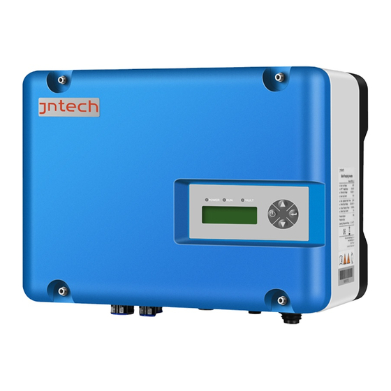
Note ! When doing solar water pump system configuration, it is necessary to ensure that the Vmp of the PV array is basically equal to or close to the AC rectifier voltage. That is, Vmp ≈ 1.414 * U wire (use a multimeter to measure the voltage between any two phases in three-phase electricity, that is, U wire), for example, Vmp of PV Module is 30V, and 18pcs in series, the Vmp of PV string is 30 * 18 = 540V ≈... - Page 16 Figure2-2 Appearance of Solar pumping inverter Table2-2 Inverter appearance information table Name Introductions LCD display Man-machine interface, you can check the inverter screen operating information through LCD display screen, also can set some function and parameters of inverter. Connection Including DC input terminal (PV+、 PV-); AC input terminals terminal (AC in);...
-
Page 17: Production Dimensions
Help machine heat dissipation, the temperature is higher when inverter is running, don’t touch! 2.2.2 Production Dimensions Figure2-3 Dimension drawing of solar pumping inverter (unit: mm) Table2-3 Inverter dimension table Inverter type Width(mm) Height(mm) Depth(mm) weight ( kg) JNP550L-V5 JNP750L-V5 JNP1K1L-V5 JNP1K5L-V5... -
Page 18: Product Name
JNP2K2L-SE-V 2.2.3 Product Name The way of product naming, take JNP2K2L for example: 2K2 L H: 380V Company name L: 220V Product series name Power level... -
Page 19: Inverter Unpacking
3 Inverter Unpacking 3.1 Unpacking Check The product has been tested and checked carefully before transportation, but damage may be caused during transportation, therefore, the product should also be checked carefully before installation. Please check whether inverter outer packing is in good condition; ●... -
Page 20: Identify Inverter
Table3-1 Inverter and fittings table Description Status Solar pumping inverter Standard Signal terminal block Standard Cold-pressed terminal (SC4-5) Standard Cold-pressed terminal (SC6-5) Standard Expansion bolt(M6*60) Standard Water level sensor B Optional Quick Installation Guideline Standard Packing list Standard Water level sensor A Optional Certificate of inspection Standard... - Page 21 Figure3-2 Inverter nameplate Table3-2 Nameplate information table Description Inverter name and model Inverter parameter information Certificate and safety signs, concrete meaning please refer to “Preface” Inverter factory number Note! Photos are for reference only, please adhere to the original products!
-
Page 22: Installation Procedure
4 Installation Procedure 4.1 Prepare Installation Tools The following tools will be needed during inverter installation and wire connection. You also can choose the right tools according to your own experience. Table4-1 Installation tools list Sketch map Name Recommend Function specification Wire M2.5~M8... - Page 23 Installation Installation instruction steps Reference chapters Before installation, check whether the inverter is in good condition; Whether the product fittings are complete Whether the installation tools and spare parts are complete Whether the installation environment meets the requirements Read the manual, especially the "Safety Instructions”...
-
Page 24: Installation
5 Installation 5.1 Installation Site Required Inverter installation site environment has very important influence to the safe operation, the performance and life of the inverter. Choose the right installation site before install the inverter. All installation must comply with local standards. ●... -
Page 25: Installation Direction
5.2 Installation Direction The inverter should be installed vertically or titled backwards with a ● maximum angle of 10°. Do not install inverter tilted forwards. ● Never install the inverter horizontally. ● Figure5-1 Installation directions The installation height of inverter should be convenient for operation ●... -
Page 26: Installation Of Inverter
100cm 100cm 100cm Figure5-2 Minimum spacing of adjacent installations Table5-1 Minimum spacing dimension Direction Minimum spacing Above 100cm Below 100cm Sides 100cm Front 100cm 5.3 Installation of Inverter Note! Do not use jacking bolts and screws install inverters on rocks or panel. - Page 27 Note! Supplier would provide the bolt which suitable for the installation on the ● concrete wall. If the inverter is fixed on the wooden wall, please choose suitable bolt to ● finish the installation, the bolt length should be enough and p enetrate the 1/2 depth of the walls.
- Page 28 Step2: Fasten the inverter lug through the expansion bolt and fix it in the positioned hole. Figure5-4 Installation of expansion bolts Step3: Tighten the bolts, make the bolts cling to the wall. Figure5-5 Installation completed renderings...
-
Page 29: Electrical Connection
6 Electrical Connection The electrical connection can be carried out when the mechanical installation of inverter is completed. The following operation specification must be followed when making electrical connection. Warning! All the electrical connection must meet local electrical connection ● standard. -
Page 30: Schematic Diagram Of Electrical Connection
Figure6-1 External connection terminals of inverter Table6-1 Description Terminals Description AC IN AC input terminals, including R/S/T/PE. PV array DC input terminals, including PV+/PV-. MOTOR Output terminal, connect with AC pump, including U/V/W. SENSOR Water level sensor signal input terminal (optional) RS485 or GPRS communication interface (optional) Ground terminal 6.2 Schematic Diagram of Electrical Connection... - Page 31 Solar pumping inverter A. PV array E. Water level sensor B. Grid F. GPRS D. RS485 module antenna C. Water pump Figure6-2 Electrical connection diagram of Solar pumping inverter Table6-2 Equipment list of solar pumping system Equipment name Description PV array The max.
-
Page 32: Cable Selection
Table 6-3 Specification of Cables for Electrical Connection Inverter Cable range( AWG) Cable recommended ( AWG) DC side AC side DC side AC side PV+、 PV- U、V、W PV+、 U、 V、 JNP550L-V5 14-12 14-12 JNP750L-V5 14-12 14-12 JNP1K1L-V5 14-12 14-12 JNP1K5L-V5 14-12 14-12 JNP2K2L-SE-V5... - Page 33 Operation Instruction Operation Demonstration Use crimping pliers to connect single-phase AC input, three-phase output and grounding wires with cold terminals (sc4-5). Step2: Fix the AC wire (R, S, PE, U, V, W) on the terminal through the corresponding waterproof terminal on the terminal cover. Note: R ground wire, s ground wire, PE ground wire, R, s, PE through the A C in waterproof terminal, U, V, W through the motor waterproof terminal.
- Page 34 The phase sequence between AC pump and inverter must be same; otherwise, it shall lead to less output or without water. Whether Phase sequence is corresponding or not should be tested when the pump system trial run for the first time.
-
Page 35: Dc Side Connection
6.5 DC Side Connection Danger! When carrying the out connection between PV array and inverter, the PV array should be covered with opaque materials and the DC-side circuit-breaker should be disconnected, otherwise, the PV array may generate dangerous voltage, cause casualty. The Non-professionals do not make the connection operation. - Page 36 1. Tighten the connection between the DC wire and the cold pressing terminal (SC6-5) with a press clamp Step2: Ensure that the DC-side circuit breaker is off. Fix the DC wire (PV+,PV-) on the terminal through the PV waterproof terminal on the terminal cover, and make sure that the positive and negative poles are not connected to each other.
-
Page 37: Water Level Sensor Connection
Warning! Make sure the plus & minus poles connection of PV array and Inverter are correct! 6.6 Water Level Sensor Connection Dry protection function: There have two kinds of detection models, automatic and manual. Automatic dry protection is achieved through inverter’s software. - Page 38 defined are shown below: Figure6-5 Water level sensor interface define Table 6-4 Description of connecting pins of water level sensor Terminal( SENSOR) Detail connector pin Dry protection pin. Overflow protection pin. Dry protection and Overflow protection common pin.
-
Page 39: Water Level Sensor Connection
Note The input signals of the above three water level sensors are passive signals, which are switching on or off signals of the corresponding water level sensors . 6.6.2 Water level sensor connection Two kinds of water level sensor you can select are shown below: Sensor Sensor Figure6-6 Water level sensor... - Page 40 Figure6-7 the detail figure of Sensor A...
- Page 41 B1 connect To SY B2 connect to COM To Wa te r le v el s en so r co nn ec to r A1 connect to DG A2 connect to COM A:the Installation location of overflow high water level sensor. B:the Installation location of overflow low water level sensor.
-
Page 42: Communication Connection
6.7 Communication Connection 6.7.1 RS485 Communication When the inverter carries on the single machine communication, the communication connection between the inverter and the monitoring equipment can be carried out through the communication cable. The Terminal COM on the the inverter is the remote communication terminal, whose output wire is connected to the monitoring device (computer). - Page 43 Table 6-5 COM terminal pin definitions on the machine panel Signal Name Description +5V power source RS48 Communication port A RS485 Communication portB Grounding The following diagram guides you to connect a single inverter to monitoring equipment. Figure6-11 Diagram of single communication wiring The wiring diagram is schematic diagram;...
-
Page 44: Gprs Communication
Note! The monitoring software is optional, when choose this function, “Inverter Management System User Manual” can be get from supplier. The inverter is supplied with default address "10". 6.7.2 GPRS Communication Note:More information about the communication module, please refer to the User and Installation Manual for GPRS. -
Page 45: Disassembling Of Connector
Notice! Electrostatic discharging will cause damage to the inner components of inverter. We should carry out the antistatic measure before disassembling and assembling. 6.8.2 Disassembling of Connector Due to maintenance and other reasons, it is necessary to disassemble the inverter cover plate. -
Page 46: Commissioning
7 Commissioning 7.1 Verify before Commissioning PV Arrays The PV array should be checked before operating the inverter, and to ensure that the positive and negative mustn’t be misconnect, otherwise, the damage may be caused to the inverter. Make sure that the open-circuit voltage of photovoltaic array doesn’t exceed the required voltage. - Page 47 Ensure that ac inputs R, S and ground connections are correct. ● Check whether the system pipeline is unobstructed or not; ● Switch on the DC-side circuit breakers. ● After finishing the above steps, then begin initialization. According to the pump motor rated current value on the nameplate, setting inverter overload protection value, the method is: modify the “Imotor”...
- Page 48 single-phase pump, special parameters of the inverter shall be set as follows: ● When the output is connected to the single-phase pump and the system is powered on, the inverter "parameter setting" interface needs to be entered. The "output selection" of the inverter is modified to "1" (" 0 "represents the three-phase inverter output,"...
-
Page 49: Stop Frequency Setting
Disconnect the DC input of the PHOTOVOLTAIC array, connect the AC input, and repeat the above operation. Note! Inverter operation refers to the output power of the inverter, drive the ● pump to work, inverter shutdown refers to the inverter to stop output power, the pump to stop working. - Page 50 Step 2: To reduce the value of “StopFreq”. Reduce 5 each time (every change need to press “ENTER” to confirm). Keep reducing till there just has no water output, and make a small change to just get small water come out, and the value is the very data of “StopFreq”.
-
Page 51: Lcd Panel Operating Instructions
8 LCD Panel Operating Instructions 8.1 Inverter LCD Display There have three LED lights, four buttons on the LCD Display, shown in figure 8-1. Figure8-1 LCD Display 8.1.1 LED Indicator Direction Table8-1 LED Indicator Direction Name Color Instructions Indicator POWER Power light Green Light on When power on. -
Page 52: Lcd Display Interface Overview
Buttons Name Functions Press once to stop; long time press “ON/OFF” for 4s to get it started. “UP” Page up and increase data. “DOWN” Page down and decrease data. “ENTER” To choose and confirm. “DOWN+ENTER” Return to main interface. Note! When inverter is powered up, LCD display background is lighted, and after 30s normal running, the background light turns off. - Page 53 START Vgrid Pgrid State_AC Fout Initialize Waiting... RunInfo Temp LCD-Ver Run Waiting ErrCode DSP-Ver StopCode SiteNum S-Mode InverterInfo D-Mode OF-F Run/Stop GPRS Hpump R_Mode Qpump npump Pump Info Pout Vday Fout Vtol Run/Stop D-Mode OF-F RunT-D RunT-T Statistic E-Day E-Tot T-Limit Para Set Pump Para Set...
-
Page 54: Initial Operational Interface
T-Value Im-Over T-Limit Im-Rate DebugMode D-Power D-Time StopFreq F-Limit Load Para Set D-Mode OF-F OF-Time M-Mode W-Mode U-Comp H-rate Pacc Q-rate Pexit Pump Para Set n-rate Poffgrid Settings S_Out (Initial password: NumValue 00) Site Num Set Clear S-Data Clear F-Data CodeValue Password Set Lang... - Page 55 Figure8-4 System initializes If the start-stop mode is auto., countdown interface will be display after initialization complete, and when countdown finished, LCD will enter the main interface, inverter will drive water pump. “RUN” indicator light. Figure8-5 Countdown interface If the start-stop mode is manual mode (factory setting), the inverter is run to drive pump after long-time pressing "ON/OFF"...
-
Page 56: System Parameter Inquiry And Setting
Figure8-6 Main interface Main interface display basic running information. Main interface will turn page auto after 10s, or you can turn page through pressing "UP" and "DOWN" button. 8.3 System parameter inquiry and setting 8.3.1 Description of inquiry information item Query information items include main interface information, operation information, basic... -
Page 57: Basic Information
Inverter input power (W). Vgrid Inverter current Grid input voltage (V) Pgrid Inverter current Grid input power (W) State_AC Inverter current Grid input situation Fout Inverter input current frequency (Hz). Inverter output U phase voltage (V) Inverter output V phase voltage (V) Inverter output W phase voltage (V) Inverter output U phase current (A). -
Page 58: Statistic Information
DSP-Ver Version information of DSP program. Site number of network node of inverter, when SiteNum communicate with RS485. Default value is 10. If modifiable, please refer to“8.3.4.4Site Number Set”. Series number of inverter. Type of inverter. Return to the previous menu 8.3.1.3 Pump Information Pump information item show the basic information of pump. - Page 59 Statistic Description Inverter daily running duration. This figure will be reset when RunT-D recharged. RunT-T Accumulative running duration.. E-Day Daily power inverted. This figure will be reset when recharged. E-Tot Accumulative power inverted Return to the previous menu 8.3.1.5 Fault Inquiry Fault Inquiry, to inquiry current and historic malfunction.
- Page 60 stop itself within the set time. Table 8-8 Description of regular downtime setting Timed Note shutdown Description information The inverter will stop automatically in minutes after reaching this time T-Value ( Minutes)。 8.3.2.2 DSP parameter setting Used for setting key parameters of solar pump inverter system. Table 8-9 DESCRIPTION of DSP parameter setting Parameter Setting...
- Page 61 This value represents the operating mode of the inverter: =0 The inverter is in economic mode; The system automatically selects power grid energy intervention according to photovoltaic energy; =1. The inverter is in a reliable mode. Power grid energy is used to ensure maximum frequency operation of the inverter when power grid input is detected by the system;...
- Page 62 To set the stopping frequency according to user F-Limit requirement, inverter will stop running automatically as setting. Default is “50Hz”. For selection of load. This figure differs by different Load pump. For choose the dry out protection mode. When water D-mode sensor is applied, dry protection mode should be set to detect dry protection.
- Page 63 During economic mode, when the solar power is lower than the access power, the grid access ensures the operation of the inverter with the maximum power.(This Pacc parameter setting is recommended to be about 45% of the load pump power, with the minimum change power of 100W.) During economic mode, when the solar power is higher than the access power, the power grid exit ensures that...
- Page 64 Note! When the user selects photovoltaic pump inverter, the parameters in the menu of "DSP Parameter Setting" have been set by factory, and these parameters cannot be changed easily. ● When the output selection is changed, the inverter must be powered off. It can only be started up again after the inverter is completely powered off.
- Page 65 Description Note Site Number Set The maximum NumValue Inverter network site number value is 64. Clear S-Data 8.3.2.5 Clear S-Data, to clear inverter’s total running time and cumulative output power. Table 8-12 Statistical Data Clear Description Note Clear Description S-Data The option is to immediately clear the inverter generation information.
-
Page 66: Information Inquiry
The default initial value for a two-digit password is 00, and Set the password to enter the the maximum value can be password Settings menu. set to 99. 8.3.2.8. Language Setting Language setting, to set the man-machine interface language category. Table 8-15 Language set description Note Language... - Page 67 Keys operation and LCD display Description main Main interface after startup; RunInfo 运行信息 2. Press to enter InverterInfo the main menu, and the cursor falls 输入电压 operation information item; ErrCode 故障代码 3. Press to enter StopCode operation information item query; 4.
-
Page 68: Parameter Setting
8.3.4 Parameter Setting Enter the correct password before entering the parameter setting interface. After entering the parameter setting menu, you can set the configurable information items given in "8.3.2 Setting Information Item Descrip tion". Here, the setting operation is demonstrated only with the example of " D-power Setting ". - Page 69 1. Enter the correct password Password to enter the setting menu, and T-Limitmit the cursor falls on the timed Para Set downtime item; T-Limit 2. Press to select the P ara Set setting item of D-power; Im-Over 3. After entering the D-power 额定电压...
- Page 70 Note! All information items given in "8.3.3 Setting Information Item Description" can be set according to the above operation, which is explained here onl y by taking the setting of D-power as an example. 8.4 Malfunction Description If communication failure appears, the below interface will appear. This interface will appear, and Fault red led flickers to show malfunction, this means internal communication malfunction is appear.
- Page 71 Table 8-16 Fault codes and status names displays fault code Name of malfunction and condition status code State 101 PV Array undervoltage Fault 102 Bus over-voltage Fault 103 Retention (bus equalizing fault) Fault 104 Radiator over heating Fault 105 Output over-load Fault 106 Array over-voltage Fault 107...
-
Page 72: Malfunction And Troubleshooting
9 Malfunction and Troubleshooting 9.1 Troubleshooting Once malfunction or stop condition appears, the malfunction LED will lighten up, LCD will display current malfunction or stop condition, current malfunction will be recorded by the system for later inquire. Please refer to the form below which covers the fault and troubleshooting. - Page 73 Inverter shut 1. Please check the Water level down until the water level, if the of source is water level water level is ok, lower than recover please check if there low-level Dry alarm protection are air inside pump. State 109 water level recover time is 2.
- Page 74 Table9-2 Malfunction and troubleshooting Cause Troubleshootin Conditio Condition Phenomen value n code Name 1. Please make sure system proper designed. The power of pump motor should not be larger than inverter output. 2. Make sure Inverter Load higher that the pump shutdown than rated...
- Page 75 Please check Inverter input maximum shutdown voltage output voltage will higher than array Array restart Fault106 over-voltage maximum make sure this automatically input voltage after voltage below inverter malfunction inverter. maximum input disappears. voltage. Input If this happen, Inverter current please contact shutdown inverter...
- Page 76 Please 1. Power inspect capacity of whether pump pump motor motor is higher normal. Inverter AC output than rated Please Inverter over current output. inspect shutdown 2. Pump whether will motor pipeline Fault108 restart locked-rot system automatically or, or accordance after the fault damaged.
- Page 77 Please Inverter check if there shutdown, is short circuit non-recover Output wire in output wires. Short circuit malfunction. Fault112 fault short 2. If this (Nonrecoverabl circuit. happen automatically frequently, restart, only please contact if recharged. supplier. Please check output wires Inverter proper Output...
- Page 78 Please check the input voltage power. local voltage value grid power Inverter high, is unstable Grid power stops, Fault200 please and high; overvoltage display disconnect the grid power. Hardware over-voltage Please failure contact supplier.
- Page 79 1. Under the 1. Please check condition of whether the AC sufficient input switch array input closed. power, 2. Please check power grid whether the local undervoltage grid voltage fails and the normal. inverter operates grid normally; power switch is not closed.; case of weak grid array...
-
Page 80: Maintenance
inverter Disconnect with shut down, input, system Grid power input, ensure start undervoltage, inverter voltage itself after or PV array voltage, Fault 203 undervoltage low voltage, or multimeter shutdown hardware check the voltage state fault. of grid power and disappears. array separately. -
Page 81: Contact Customer Service
Check whether the parameters and time settings are correct. ● Every half to one year, a routine examination should be done: Warning! Please check and make sure the inverter is not charged with electricity before any maintain work below. Check humidity and dust of inverter surrounding environment, if have ●... - Page 82 10 Appendix A Technical Data Item/ Model JNP550L-V5 JNP750L-V5 JNP1K1L-V5 JNP1K5L-V5 JNP2K2L-SE-V5 DC input Max. input DC 450Vdc input Recommended 105~400 150~400 MPPT voltage 80~400 Vdc 130~400 Vdc 150~400Vdc range Max. input DC current MPPT efficiency Input number of string...
- Page 83 Rated output current Mechanical Data Size(W/H/D) 278/370/125(mm) Weight 6.5kg System parameter Max. efficiency Protective class Protection level IP65 Operation temperature -25℃ to +60℃, above 60℃ need rated operating range Cooling Nature air cooling methods Display Communication RS485/GPR, WiFi without LCD interface Altitude 3000m;...
-
Page 84: Quality Assurance
11 Appendix B 11.1 Quality Assurance The product malfunction in the warranty period, supplier will be free repair or replacement products. The warranty period take the contract as a standard. Evidence During the warranty period, customers should provide the invoices for the purchase of products and date. -
Page 85: Contact Us
11.2 Contact Us If you have any question about Solar pumping inverter, please contact us, and we will be happy to give you answers.
Need help?
Do you have a question about the JNP550L-V5 and is the answer not in the manual?
Questions and answers