
Related Manuals for Jntech JNF1KLF-A/24V


Summary of Contents for Jntech JNF1KLF-A/24V
- Page 1 PV Off Grid Inverter with Hybrid Controller User Manual Hefei Jntech New Energy Co.,Ltd.V1.0...
-
Page 2: Table Of Contents
Content 1.Safety Instruction ...................... 1 1.1 Safety identification ..................1 1.2 Safety instruction ..................... 2 2.Production Introduction ................... 4 2.1 Household PV off-grid Power Generation System Introduction ..... 4 2.2 Production Introduction ................... 5 2.2.1 Appearance Introduction ................. 5 2.2.2 Production Dimensions ................6 3.Inverter &... -
Page 3: Safety Instruction
1.Safety Instruction 1.1 Safety identification The following safety symbols may be used in this manual, and the meanings are shown in below. Safety Symbol Meaning Means that it may lead to serious accident of injuries, if Danger safety warning is ignored. Means that it may lead to serious accident of injuries, Warning equipment serious damage or main business interruption, if... -
Page 4: Safety Instruction
Notice! When you receive the product, please check the damage of the whole machine during the transportation. If you find any problems, please contact Hefei Jntech new energy Co.,Ltd. or transportation company immediately ○ Installing Ensure inverter not have electrical connections and electricity before installing. - Page 5 Electrical connection: Warning! All the operation and wiring work should be operated by professional ● electrical or mechanical engineer. Please do not close any circuit breakers until all devices are fully connected ● Notice! All electrical installation must comply with local and national electrical ●...
-
Page 6: Production Introduction
2.Production Introduction 2.1 Household PV off-grid Power Generation System Introduction Household PV off-grid power generation system consists of PV array、solar mounting structure、storage battery、Grid(Diesel Generator)、PV off-grid inverter with controller and conventional household loads. Use PV solar panel transform solar energy into electrical energy, meanwhile use solar controller store electrical energy into battery, inverter can transform battery’s DC power into 115V AC power and 230V AC power to drive household loads work. -
Page 7: Production Introduction
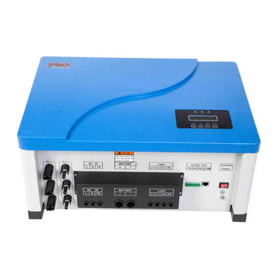
2.2 Production Introduction 2.2.1 Appearance Introduction Figure 2-2 Production Appearance Diagram2-1 Production Appearance Information Serial Number Name Description PV Input Input terminals,connect with PV array. AC Input Connect with grid power or Diesel Generator. Battery Terminals Connecting with battery array. Display current working status and parameter modify LCD display functions. -
Page 8: Production Dimensions
2.2.2 Production Dimensions Hight Depth Width Figure 2-3 Inverter & Controller Dimensional Drawing (mm) Diagram 2-2 Inverter & Controller Size and Weight Sheet Model No. W(mm) H(mm) D(mm) W(kg) JNF1KLF-A/24V JNF1K5LF-A/24V JNF2KLF-A/24V JNF3KLF-A/48V JNF4KLF-A/48V JNF5KLF-A/48V... -
Page 9: Inverter & Controller Unpacking Installation
3.Inverter & Controller Unpacking Installation 3.1 Unpacking Inspection To ensure system installation goes smoothly, pls do checking before unpacking. Specific inspection items are as follows: ● Checking whether the outer packing is in good condition. ● Unpacking, and checking up the products damage or not. ●... -
Page 10: Prepare Installation Tools
3.2 Prepare Installation Tools Inverter & controller installation and guide line installation tool are as follows, installation workers need to use tool as per request of follow sheet without any mistake. Diagram 3-2 Installation Tool List Diagram Name Recommend Function sketch ed spec. - Page 11 Model of Inverter & Controller JNF5KLF-A/48V L:459mm H:245mm L:454mm JNF1KLF-A/24V JNF1K5LF-A/24V JNF2KLF-A/24V H:200mm JNF3KLF-A/48V JNF4KLF-A/48V Step 3:Refer to follow installation method to finish the installation. 2.Screw out nut,hang on inveter with controller,use 1.Use churn drill to punch about dia.80mm hold monkey spanner to tighten nut,then finish installation of on the location of wall or panel board.put setscrew...
-
Page 12: Electrical Connection
Air-switch selection(C) Cable selection(AWG) Model No. Load1 Load2 Load1 Load2 JNF1KLF-A/24V JNF1K5LF-A/24V JNF2KLF-A/24V JNF3KLF-A/48V JNF4KLF-A/48V JNF5KLF-A/48V Above diagram, the selection of C shows normal type auto breaker ,after C Digital said over rated current; cable selection in AWG American Standard refers to the diameter of the cable wire. -
Page 13: Ac Input Connection
10mm 1.Use wire stripping pliers to strip 2.Insert pressed cable into waterproof 3.Insert waterproof terminal into inverter 10mm,then use Crimping Pliers to terminal,pls note positive pole and separately,finish making and connecting press terminal. negative pole,tighten nut. pv side terminal. Figure 3-5 PV Array Terminal Making and Connecting Diagram Step 3: During cable connecting of PV input side, insert PV cable of PV array into auto Air-switch respectively according to positive pole and negative pole;... - Page 14 Step 1: Please according to follow methods, making Grid power side cable connection and connectors. 10mm 3.Use cross opener to tighten screw,then 1.Use wire stripping pliers to 2.Insert pressed cable into protective cover and tighten protective cover,finish strip 10mm,then use Crimping cover.
- Page 15 Step 2: If diesel generator’s start mode is NO (normally open), then insert diesel generator’s NO terminal into inverter & controller’s NO terminal accordingly; If diesel generator’s start mode is NC (normally close), then insert diesel generator’s NC terminal into inverter& controller’s NC terminal accordingly; Ensure the connecting of NO-NO or NC-NC is correct, specific connection mode, please refer to follows for details.
-
Page 16: Battery Connection
(2)Ensure battery side’s air switch in off state. (3)Avoid battery being short circuit during its installation. Step 1: According to nameplate to confirm the battery pack voltage, JNTECH PV hybrid power generating system’s battery pack voltage could refer to follow sheet. - Page 17 Battery Input Terminal Battery — Figure 3-12 Battery Input Side Cable Connecting Diagram 3.4.3.2 Battery TB Side Connection Inverter & controller is in power off, switch off state. Step 1: Measure line distance between TB side to battery pack, choose suitable length cable.
-
Page 18: Ac Output Connection
Figure 3-14 TB Side Cable Connecting Diagram 3.4.4 AC Output Connection Inverter & controller is in power off, switch off state. Step 1: Making AC output side terminals according to following method: 10mm 1.Use wire stripping pliers to strip 3.Use cross opener to tighten screw,then 2.Insert pressed cable into protective 10mm,then use Crimping Pliers to cover and tighten protective cover,finish... -
Page 19: Communication Connection
Figure 3-16 AC Output Side Cable Connecting Diagram Illustration! Over load is forbid for PV hybrid inverter & controller. 3.4.5 Communication Connection Step 1: Before communication interface connecting, please check follows items: (1) Ensure PV hybrid inverter & controller is in power off, switch off state ; (2) Please clear the communication interface, ensure there is no foreign matters. -
Page 20: Commissioning
4.Commissioning 4.1 Electrical Connection Inspection before Commissioning Before commissioning, electrical connection inspection should be done strictly, to ensure safety of the inverter & controller as well as the personal safety; To prevent accidents, specific inspection items as follows: (1)Check whether the PV open circuit voltage is within the allowable voltage range of the inverter &... -
Page 21: Grid Power Charging Commissioning
4.2.2 Grid Power Charging Commissioning To ensure grid voltage is normal, firm connecting, specific operation steps as follows: Step 1: Open power switch, then turn on air-switches of grid input side and battery side; Step 2: Enter into the dispatching mode, change from Charging dispatching mode to power grid mode (specific operation refer to chart 4-16), waiting one minute, then check grid power charging state, LCD display “Charging”... -
Page 22: Grid Pass-By Output
Figure 4-3 Normal Inverting Working of LCD Display Diagram Step 2: LCD display inverter output is normal, press ON/OFF key, switch off inverting output, finish battery power’s inverter output commissioning. 4.3.2 Grid Pass-by Output Ensure grid voltage is normal, Grid supply power directly. No more other input interfaces, specific operation step as follows: Step 1: Turn off grid side air-switch, then check if grid voltage is normal. -
Page 23: Union Commissioning
controller to see if diesel generator can start. Long press ON/OFF button for more than 2S to check whether pass-by output is normal. AC voltmeter shows voltage be 220V± 15%, LCD indicator light is in green and flashing, specifics as follows: Ugrid 223V Igridchg... -
Page 24: Lcd Panel Operating Instructions
Step 3: LCD display status is normal, turn off all air-switches and power switch, finish union commissioning. 4.5 LCD Panel Operating Instructions 4.5.1 LCD display Inverter & controller have LCD display and LED display function, we can check system working information and set up key parameters. Meanwhile, LED light indicating inverter &... -
Page 25: Lcd Display Interface
4.5.2 LCD Display Interface Follows are LCD display general block diagram, easy to know distribution of LCD operation. Bat-Cap Ub-rate Ub-const Ib-const Ipvchg Ub-float Ugrid Ib-float Igridchg Ub-over RunInfo Ubat Ub-recover Battery Pchg T-Comp Pout START Ut-up Uout Ut-down IoutL1 IoutL2 Poff Initialize... -
Page 26: Lcd Display Content
4.5.3 LCD Display Content Turn on LCD, “Initialize Waiting…”appears, 3S later display interface shows as follow: 0.0V Ipvchg 0.0A Ugrid Igridchg 0.0A Ubat 0.0V Batlevel Pchg Pout Uout IoutL1 0.0A IoutL2 0.0A Fout 0.0Hz Figure 4-9 LCD Display Interface Show LCD display interface’s content and function explanatio, please reference to appendix A Diagram 6-1. -
Page 27: Lcd Display Function Information And Basic Operation
4.5.4 LCD Display Function Information and Basic Operation 4.5.4.1 LCD’s Working Information and Its Basic Operation Followings are LCD’s working information block diagram, could help you easy to know its operation process: 0.0V RunInfo Ipvchg 0.0A InverterInfo Ugrid 光伏电压 0.0V 0.0V StatusInfo Igridchg... - Page 28 4.5.4.2 LCD Basic information and Its Basic Operation Follows are LCD basic information operation block diagram, could help you easy to know the basic information operation process: 0.0V Ipvchg 0.0A Ugrid RunInfo RunInfo Igridchg 0.0A InverterInfo InverterInfo Ubat 0.0V StatusInfo StatusInfo Batlevel Pchg...
- Page 29 4.5.4.3 LCD’s Statistical Information and Basic Operation Follows are LCD’s statistical information block diagram, could help you easy to know its operation process: 0.0V Ipvchg 0.0A Ugrid RunInfo RunInfo Igridchg 0.0A InverterInfo InverterInfo Ubat 0.0V StatusInfo StatusInfo Batlevel Pchg Settings Settings UP/DOWN ENTER...
- Page 30 4.5.4.4 LCD Parameter Setting and Basic Operation Follows are LCD Parameter Setting operation block diagram, could help you easy to know its operation process: 0.0V RunInfo RunInfo Ipvchg 0.0A InverterInfo InverterInfo Ugrid StatusInfo StatusInfo Igridchg 0.0A ENTER UP/DOWN Settings Settings Ubat 0.0V Batlevel...
- Page 31 4.5.4.5 LCD Malfunction Information and Basic Operation Followings are LCD malfunction information operation block diagram,could help you easy to know its operation process: 0.0V RunInfo RunInfo Ipvchg 0.0A InverterInfo InverterInfo Ugrid StatusInfo StatusInfo Igridchg 0.0A ENTER UP/DOWN Settings Settings Ubat 0.0V Batlevel Pchg...
- Page 32 4.5.4.6 LCD Dispatching Settings and Its Basic Operation Grid CHG AUTO GRID AUTO 输出模式 Power GRID DIESEL Load-Set Figure 4-16 Dispatching Settings Classification Diagram Chart 4-3 Dispatching Settings Classification Illustration Dispatching Settings Function Illustration ON: Enable Grid Charging Grid Charging OFF: Power Off Grid Charging AUTO: Intelligent dispatch Charging Dispatch...
- Page 33 Following is the LCD dispatching setting operation block diagram. It can be simple and clear understanding of dispatching setting operation process: 0.0V RunInfo RunInfo Ipvchg 0.0A Ugrid InverterInfo InverterInfo Igridchg 0.0A StatusInfo StatusInfo Ubat 0.0V Settings Settings ENTER Batlevel UP/DOWN Pchg FaultInfo FaultInfo...
-
Page 34: Common Troubleshooting And Maintenance
Status name Machine Possible reason Processing method phenomenon Fault light is on Please contact Fault 100、 Over and whole Jntech customer Inside fault charging machine stops service working Check whether the fan is working Fault light is on Cooling function normally. - Page 35 Fault light is on Please contact abnormal and the whole Jntech customer Fault 200、 inversion of machine stops inside fault. service voltage and working current Please contact Jntech customer...
-
Page 36: Maintenance
5.2 Maintenance Before maintenance, please ensure the machine is not charged, Make a routine inspection for inverter with charger as following every half year. Check whether there is damage or deformation ● Check whether there is abnormal noise in the inverter with charger. ●... - Page 37 6. Appendix A LCD menu and parameters setting as follows: Table 6-1 LCD priority screen display content Display content Function declaration PV panel Voltage Display PV array present voltage. PV panel charging Display PV array present charging current. Grid Power voltage Display the present grid AC voltage.
- Page 38 Return to previous layer menu. Secondary menu Function declaration (Basic information) LCD-version Display present LCD screen version number DSP-version Display present DSP version number SYS-SN Display present machine model number. SiteNo. Display present machine site number. SN numver Display present machine series number. Return to previous layer menu.
- Page 39 Constant charging current Charging current during the machine in constant charging status. Floating charge voltage Charging voltage during the machine in floating charging status. Floating charge current Charging current during the machine in floating charging status. status. Overvoltage disconnection When the battery voltage exceeds the set value, break off the charging function.
- Page 40 7.Appendix B Technical Parameter JNF1KLF- JNF1K5LF- JNF2KLF- JNF3KLF- JNF4KLF- JNF5KLF- Model A/24V A/24V A/24V A/48V A/48V A/48V PV Input Max. PV array input 150Vdc 150Vdc 150Vdc 150Vdc 150Vdc 150Vdc voltage PV Input 1500W 1500W 1500W 3000W 3000W 4000W Power MPPT Voltage 35~145Vdc 35~145Vdc...
- Page 41 AC input 60Hz (± 3%) frequency Max.charge current Grid by-pass Allowed input 115Vac± 10% 115Vac± 10% 115Vac± 10% 115Vac± 10% 115Vac± 10% 115Vac± 10% voltage /230Vac± 20% /230Vac± 20% /230Vac± 20% /230Vac± 20% /230Vac± 20% /230Vac± 20% Switching <100ms Time Machanical Data Dimension(W 485mm*365m...
- Page 42 8.Appendix C Inverter with charger fault feedback information table Production information Model Serial number Purchase time Utility time Product usage Specific load model Fault code Fault information Fault phenomenon Fan runs or not Fan condition Fan operation PV panel model Group string information PV panel settings Battery model...
- Page 43 9.Appendix D Quality assurance The product malfunctions in the warranty period, Hefei Jntech new energy Co. Ltd.( referred to as our company) will be free maintenance or replacement of new product. The product warranty period shall be subject to the contract.
- Page 44 This document relates to the patents and confidential information of Hefei Jntech New Energy Co., Ltd. It is not allowed to copy, take pictures and distribute online, without the permission of Jntech company. Hefei Jntech New Energy Co., Ltd. has rights to modify the user manual.
Need help?
Do you have a question about the JNF1KLF-A/24V and is the answer not in the manual?
Questions and answers