
Related Manuals for Jntech JNF3KLF24V-V2


Summary of Contents for Jntech JNF3KLF24V-V2
- Page 1 User Manual PV Off-Grid Inverter With Controller JNF3KLF24V-V2 JNF3KLF48V-V2 JNF4KLF48V-V2 JNF5KLF48V-V2 JNF3KLF24V-A-V2 JNF3KLF48V-A-V2 JNF4KLF48V-A-V2 JNF5KLF48V-A-V2 JNF5KLF-V2-EN-V2.0...
- Page 2 Copyright belongs to Supplier This document relates to the patents and confidential information of Supplier It is not allowed to copy, take pictures and distribute online, without the permission of supplier. Supplier has rights to modify the user manual.
-
Page 3: Table Of Contents
Content 1 Safety Instruction........................1 1.1 Safety identification......................1 1.2 Safety instruction......................2 2 Products Introduction......................5 2.1Household PV off-grid Power Generation System Introduction......5 2.2 Product Introduction.......................6 2.2.1 Appearance Introduction..................6 2.2.2 Production Dimensions..................7 3 Inverter & Controller Unpacking Installation..............9 3.1 Unpacking Inspection.................... -
Page 5: Safety Instruction
1 Safety Instruction 1.1 Safety identification The following safety symbols may be used in this manual, and the meanings are shown in below: Safety Symbol Meaning Indicates that if safety warnings are ignored, serious Danger accidents may result in personal injury; Pay attention to the polarity of the connection, do not connect wrong, there is a risk of damage. -
Page 6: Safety Instruction
life and personal security of operating person or the third party, and inverters. In order to reduce casualties, damage of inverter&controller and other equipment, user or operating person should strictly abide by all the safety information tips of danger, warning and notice which are in the process of operating and maintaining 1.2 Safety instruction Warning!... - Page 7 Warning! If inverter damage caused by the following circumstances will be beyond the warranty scope of our company. The PV array configuration should ensure the max. short-circuit ● current of DC side within the allowable range of inverter & controller, otherwise it may cause irreversible damage to inverter &...
- Page 8 Cable connection must select the appropriate specifications, firm ● connection and good insulation. In operation ○ Danger! Please do NOT open the device cover when the device is with ● electricity! Repair ○ Danger! Maintenance work should be carried out by professional maintenance technicians.
-
Page 9: Products Introduction
2 Products Introduction 2.1Household PV off-grid Power Generation System Introduction Household PV off-grid power generation system consists of PV array、solar mounting structure、storage battery、Grid(Diesel Generator)、PV off-grid inverter with controller and conventional household loads. Use PV solar panel transform solar energy into electrical energy, meanwhile use solar controller store electrical energy into battery, inverter can transform battery’s DC power into single phase AC power to drive household loads work. -
Page 10: Product Introduction
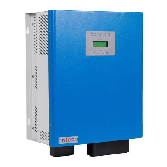
2.2 Product Introduction 2.2.1 Appearance Introduction Figure 2-2Appearance of inverter & controller Diagram2-1Information of inverter & controller appearance Name Description Overload Overload protection reset protection device Common machine: AC input is connected to power grid or diesel generator (L is AC source fire line, n is AC source zero line, PE is grounding protection;... -
Page 11: Production Dimensions
Display current working status and parameter modify LCD display functions. Protection cover Protection cover of terminal “AC IN” and “Load”, protect of terminals terminals from corrosion and person from electric shock RS485 communication function, can connect Communication communication transform equipment, to monitor the Interface working status of the whole system. - Page 12 Net Weight Model No. (mm) (mm) (mm) ( kg) JNF3KLF24V-V2 JNF3KLF24V-A- JNF3KLF48V-V2 JNF3KLF48V-A- JNF4KLF48V-V2 JNF4KLF48V-A- JNF5KLF48V-V2 JNF5KLF48V-A- In order to meet the voltage requirements of different national power grids, the all-in-one machine models are divided into two series: ordinary and American...
-
Page 13: Inverter & Controller Unpacking Installation
3 Inverter & Controller Unpacking Installation 3.1 Unpacking Inspection To ensure system installation goes smoothly, please check before unpacking. Specific inspection items are as follows: Check whether the outer packing is in good condition. ● Unpack, and check up the products damage or not. ●... -
Page 14: Prepare Installation Tools
Standard Quality Certification Standard User manual 3.2 Prepare Installation Tools Inverter & controller installation and wire installation tools are as follows,installation workers need to use tools as per request of follow sheet without any mistake. Diagram 3-2 Installation Tools List Diagram Name Recommended... - Page 15 As shown in the figure: Figure 3-3 Hang position diagram Follows are wall hanging sizes of different inverter & controller models: Diagram 3-3 Fixed position sizes chart Position size Model of Inverter & Controller L:349mm JNF3KLF24V-V2 JNF3KLF24V-A-V2 H: 316mm JNF3KLF48V-V2 JNF3KLF48V-A-V2 JNF4KLF48V-V2 JNF4KLF48V-A-V2...
-
Page 16: Electrical Connection
Diagram 3-4 Selection of Inverter & Controller breaker and cable model Breaker selection Cable selection( AWG) Inverter & Controller Load Load model JNF3KLF24V-V2 JNF3KLF24V-A-V2 JNF3KLF48V-V2 JNF3KLF48V-A-V2 JNF4KLF48V-V2 JNF4KLF48V-A-V2 JNF5KLF48V-V2 JNF5KLF48V-A-V2 Note: AWG of cable selection means American Standard, indicating... -
Page 17: Pv Input Connection
3.4.1 PV Input Connection Step 1: Do the following inspections before PV side terminal connecting: Please make sure system’s DC air-switch on PV side is in off state, before connecting with PV array. Please ensure PV array’s polarity be matched with PV connectors’ polarity, to avoid inverter &... -
Page 18: Ac Input Connection
Figure 3-5 schematic diagram of photovoltaic terminal production and connection Step 3: During cable connecting of PV input side, insert PV cable of PV array into auto Air-switch respectively according to positive pole and negative pole; then insert the two cables which made in Step 2 into Air-switch separately. - Page 19 Ordinary machine: AC IN screen printing for L, N, PE American standard machine:American standard machine: AC IN screen for L1, L2, N 3、 Screw down the cable inserted into the protective cover corresponding to the terminal connected to the box AC IN screen printing and tighten it with a word screw driver, then tighten the protective cover on the cover to complete the terminal...
- Page 20 American standard machine:Connect the cables at the end of the grid to the air switch according to L1 (fire line 1 phase), L2 (fire line 2 phase) and N (zero line) respectively. Keep ac side space open and off. Step 3: Then connect the other end of the cable made in Step 1 to the open space and check whether the connection is correct and firm.
- Page 21 1、Use stripping pliers to strip the cable for 10mm 2、 According to the starting signal of the diesel engine, insert the cable into the NO terminal or the NC terminal, and tighten the screw 3、 Insert the screwed terminals into the NO and NC terminals of the all-in-one machine to complete the terminal connection of the diesel engine...
-
Page 22: Battery Connection
Step 1: According to nameplate to confirm the battery pack voltage, PV hybrid power generating system’s battery pack voltage could refer to follow sheet. Diagram 3-5 Battery Pack Voltage Selection List Battery Pack Inverter & Controller Model No. Voltage JNF3KLF24V-V2 JNF3KLF24V-A-V2 JNF3KLF48V-V2 JNF4KLF48V-V2 JNF5KLF48V-V2 JNF3KLF48V- A-V2 JNF4KLF48V- A-V2... - Page 23 Step 2: Cable making and connecting, please refer to follow method: 1、 Use stripping pliers to strip the cable for 10mm 2、 Press the upper terminal with line clamp 3、 Insert the pressed cable into the protective cover accordingly 4、 Screw M6*16 and M6 nut to fix the cable inserted into the protective cover on the terminals connected to the box BAT- and BAT+ screen printing, then tighten the protective cover on the cover to complete the terminal connection of the battery...
-
Page 24: Ac Output Connection
Figure 3-11 Battery Terminal Making and Connecting Diagram Step 3:Firstly, connect the cables of the battery terminal to the air opening according to the corresponding positive and negative poles (during connecting the cables, the positive and negative poles of the battery must not be in contact);... - Page 25 Common machine: AC OUT screen printing is L, N, PE American standard machine:AC OUT screen printing is L1, L2, N, PE 3、 Screw down the cable inserted into the protective cover corresponding to the terminal connected to the AC OUT screen printing in the case and tighten the word screw driver, then tighten the protective cover on the cover to complete the AC output terminal terminal connection...
- Page 26 Step 2:Wiring of ac load terminal: Common machine:Connect the cable at the ac load end to the air open according to L (fire line) and N (zero line) respectively, and PE ground; Keep the load side open and open. American standard machine:The cables at the end of the power grid are connected to the air switch according to L1 (fire line 1 phase), L2 (fire line 2 phase) and N (zero line) respectively, and PE is earthed.
-
Page 27: Communication Ports Connection
3.4.5 Communication Ports Connection Step 1: Before communication interface connecting, please check follows items: (1) Ensure PV hybrid inverter & controller is in power off, switch off state ; (2) Please clear the communication interface, ensure there is no foreign matters. - Page 28 Orange & White and Brown(Line order 1、8) corresponding to communication terminal 5V and GND of 485) Step 3: Connecting appliances needed for communication (such as computer, communication module. etc) with inverter & controller through COM interface. Follows are control interface connection figure: Control port input Computer Convertor...
-
Page 29: Commissioning
4 Commissioning 4.1 Electrical Connection Inspection before Commissioning Before commissioning, electrical connection inspection should be done strictly,to ensure safety of the inverter & controller as well as the personal safety; To prevent accidents, specific inspection items as follows: (1) Check whether the PV open circuit voltage is within the allowable voltage range of the inverter &... - Page 30 parameters are also in good condition of configuration and debugging. Other uncertain battery parameters need to be configured according to the following table (the all-in-one machine can be modified after running). Table 4.1 Description of menu items related to battery setting. type of menuitem set value...
- Page 31 SystemSet-->BatterySet-->BMSEn Please contact the supplier to set parameters for AXE-485/ supporting only SystemSet-->BatterySet-->BMSTy CSW-485/ the lithium NG-CAN/ batteries CSW-V20 configured by our company and other lithium batteries. According to the actual number of SystemSet-->BatterySet-->PackNu parallel lithium lithium battery packs battery configured.
- Page 32 Step 2: Check the photovoltaic input voltage before closing the photovoltaic side to open K2; Step 3: Check the input voltage of AC source and close the ac source side to open K3(if there is no power grid, there is no need to operate;...
-
Page 33: Liquid Crystal Operation Instructions
4.3 Liquid crystal operation instructions 4.3.1 All-in-one LCD display The all-in-one machine is equipped with LCD and LED display functions. It can view the all-in-one machine operation information through LCD and set key parameters by combining with the keys. At the same time, the LED light indicates the current running state of the all-in-one machine. -
Page 34: Liquid Crystal Display Interface
close No fault Table 4-3 Key description table button function back 1.Turn the menu up; 2.Data set value increment operation。 1.Turn the page; DOWN 2.Data reduction。 Go to the next level menu; ENTER Set values to modify and save。 Press at the same time to return to DOWN+ENTER the priority screen 4.3.2 LIQUID crystal display interface... -
Page 35: Contents Of Lcd Display
Figure 4-3 LIQUID crystal display block diagram 4.3.3 CONTENTS of LCD display After the LCD is powered on, "Welcome to use" will appear. After 3 seconds, the priority screen interface will jump to the following figure: Figure 4-4 LCD priority screen interface display Table 4-4 LCD priority screen display contents... - Page 36 display content function declaration Ubat Displays the current voltage of the battery. Ibat Display current current value of battery, negative value is discharge. Displays the current voltage value of the PHOTOVOLTAIC array. Displays the current input current value of the PHOTOVOLTAIC array.
-
Page 37: Liquid Crystal Function Information
4.3.4 Liquid crystal function information 4.3.4.1 Operating information of LIQUID crystal The information status of the main parameters of the current system is displayed. Figure 4-6 Operation information operation interface... - Page 38 Table 4-6 Liquid crystal operation information operation interface display contents secondary menu function declaration (Operation information) Displays the current voltage value of the PHOTOVOLTAIC array. Displays the current input current value of the PHOTOVOLTAIC array. Displays the current input power value of the PHOTOVOLTAIC array.
- Page 39 Bypass Shows bypass operation status. GChg Display the charging status. Diesel Display the working status of diesel engine. ExtComm Displays external communication status. BMSComm Displays the BMS communication status. 4.3.4.2 Liquid crystal fault information and its basic operation The current fault records the current fault, the historical fault records the historical fault, the historical fault 1 represents the nearest fault to the current time (or the current fault), the historical fault 2 is the fault before the historical fault 1, and so on.
- Page 40 Figure 4-8 LCD statistical information operation interface Table 4-8 Display contents of LCD statistical information operation interface secondary menu function declaration (Statistics) Ene-pv Display statistics of the total output of the current photovoltaic system. Ene-Inv Display statistics of the current system total inverter power.
- Page 41 4.3.4.5 Energy management of LIQUID crystal and its basic operation Ac source Settings changed: Power dispatch - AC source: power grid and diesel engine. The default grid mode can be changed to diesel engine mode according to customer demand. When selecting the diesel engine with AC source, it is necessary to ensure that the starting signal line of the diesel engine is normally connected to the communication interface of the dry contact of the all-in-one machine, and that the output end of the diesel engine is...
- Page 42 RunMode Set the operating mode of the system. When debugging mode is selected, the machine runs in Debug debug mode first. ACSource Ac bypass input selection for an all-in-one machine. In the economic mode, the power grid has power, the power grid charging enables, the photovoltaic charging I-Gch-L current <...
- Page 43 4.3.4.6 LCD system Settings The battery setting in the system setting requires the password to enter. The default password is 0000. When using lead-acid batteries, set the BMS enabling item to disabled. When lithium battery is used, BMS enabling item should be set as enabling, and corresponding BMS type and PACK number should be selected.
- Page 44 Figure 4-11 Operation interface of parameter setting Table 4-12 Contents of LCD parameter setting operation interface secondary menu (System function declaration Settings,pass word: 0000) BatterySet Set battery parameters. Site Set the device address for external Modbus communication LcdLight Set the backlight lighting time when the all-in-one machine is working.
- Page 45 Ub-Rate Set the rated voltage of the battery used in the system. Ub-Const The charging voltage value of an all-in-one machine under constant voltage charging state. Ib-Const The charging current value of an all-in-one machine when it is in constant current charging state. Ub-Float The charging voltage of the all-in-one machine in floating charging state.
-
Page 46: Common Troubleshooting And Maintenance
5 Common troubleshooting and maintenance 5.1 Troubleshooting Once the all-in-one machine fails, the fault light will be on and the LCD screen will display the current fault information. Users can query the fault information according to the fault code. The following table provides some basic fault troubleshooting methods. - Page 47 the chassis 2. Check whether the inlet and outlet of the chassis are blocked 3. Check whether all fans are running normally Yellow light Schottky Temp. sensor contact the alarm temperature terminal loose customer service Machine sensor failed running 1.The undervoltage of the array is Yellow light...
- Page 48 aging or not contact the Storage rw fault hardware failure customer service 1. Check whether Whether the the battery side machine battery is switch is closed overpressur connected 2. Check the e point: 32V Bat overvoltage Cell aging battery voltage Overpressu Abnormal battery level...
- Page 49 all fans are running normally The load Reduce load and Invert output exceeds the not exceed overload rated capacity of nameplate the machine capacity Long time Reduce load or Invert transformer operation at full stop inverter wait overheating power for a few hours Inverter up mos temperature The temperature...
- Page 50 Grid lock phase error Invert relay KM1 turn on fault Grid relay KM3 contact the turn on fault hardware failure customer service Soft start fault Slave init error Basic fault information of lithium batteries Lithium fault fault battery implication handling method remark code phenomenon...
- Page 51 below 0℃ The discharge Please restart the overcurrent is inverter after detected reducing the load continuously for 10s, and the Dsicharge inverter is overcurrent stopped. The alarm is detected continuously for 3 times within 2 minutes Continuously Restart the detect charging inverter overcurrent for Charge...
- Page 52 circuit is constantly on Stop charging The inverter is and discharging controlled by Single the battery. The itself without undervoltage battery's main operation circuit is constantly on Stop charging The inverter is and discharging controlled by of the battery, itself without disconnect the operation Bat overvoltage...
- Page 53 Stop charging The inverter is and discharging controlled by of the battery, itself without disconnect the operation OCCHG main circuit of the battery, and resume after a delay of 1h Stop the battery Please contact charging and the manufacturer Monomer discharging, and to replace the unbalance...
- Page 54 Stop discharging The inverter is Discharge the battery and controlled by overcurrent keep the battery itself without warning main circuit open operation Stop charging The inverter is Overcurrent charge the battery and controlled by warning keep the battery itself without main circuit open operation Stop charging...
- Page 55 correctly Yellow light Lcd eeprom contact the alarm hardware failure storage error customer service Machine running The inverter is controlled by PXX-00 Bat cell invalid stop charging itself without operation Start the power Please charge in Single PXX-01 grid charging, time when the overvoltage stop the inverter...
- Page 56 temperature environment of battery pack or the battery pack transfer it indoors is not suitable below 0℃ Dsicharge high Stop charging, contact the PXX-07 temperature stop inverter customer service The working environment of Please heat the Dsicharge low PXX-08 the battery pack battery pack or temperature is not suitable...
- Page 57 below 0℃ environment of Stop charging, contact the PXX-61 stop inverter customer service high temperature The working environment of Please heat the environment of PXX-62 the battery pack battery pack or low temperature is not suitable transfer it indoors below 0℃ power of high Stop charging, contact the...
-
Page 58: Maintenance
5.2 maintenance Before the maintenance of the all-in-one machine, it shall be ensured that the all-in-one machine is not electrified. The following routine checks shall be carried out on the all-in-one machine every six months: ● Check whether the all-in-one machine is damaged or deformed. ●... -
Page 59: Appendix A Technical Parameters
6 Appendix A technical parameters Normal machine JNF3KLF24V-V2 JNF3KLF48V-V2 JNF4KLF48V-V2 JNF5KLF48V-V2 model PV Input Maximum input DC 180Vdc voltage 3500W 5000W 7000W 7000W Recommended input power MPPT working 35~170Vdc 65~170Vdc 65~170Vdc 65~170Vdc voltage range Battery nominal voltage 24Vdc 48Vdc 48Vdc... - Page 60 AC INPUT alternating voltage 230Vac±20% alternating current 50/60Hz (±3%) frequency maximum charging current Ac bypass Allowable input 230Vac±20% voltage switching time ≤10ms Machine Parameters 440*370*190mm dimensionality H/D) weight 29Kg 30kg 31kg 33kg Miscellaneous Protection grade IP20 Noise <60dB Cooling Method forced cooling operating -20~+50℃...
- Page 61 Maximum charging ≥97% efficiency Battery Information Gel/lithium Inverter output Max short circuit L1~L2: 3000VA L1~L2: 3000VA L1~L2:4000VA L1~L2: 5000VA current L~N:1500VA L~N:1500VA L~N:2000VA L~N:2500VA Peak output L1~L2: L1~L2: 9000VA L1~L2: 9000VA L1~L2: 12000VA capacity 15000VA L~N:4500VA L~N:4500VA L~N:6000VA L~N:7500VA Rated output L1~L2:3000W L1~L2:3000W L1~L2:4000W...
- Page 62 <60dB forced cooling cooling method operating -20~+50℃ temperature critical -25~+70℃ temperature status indicator LCD+LED port RS485/CAN(Optional) altitude 2000m(>2000m Derating work...
- Page 63 7 appendix B Quality assurance Products in the warranty period of failure, our company will free maintenance or replacement of new products. The warranty period of the products shall be subject to the contract. evidence During the warranty period, the customer is required to produce the invoice and date of the purchased product.
- Page 64 8 Appendix C All in one machine user fault feedback information table Product Information Factory serial product model number cost of time Life timer Product status load model fault code fault message fault phenomenon Whether the fan is running running condition Solar panel...
Need help?
Do you have a question about the JNF3KLF24V-V2 and is the answer not in the manual?
Questions and answers