Table of Contents
Advertisement
Quick Links
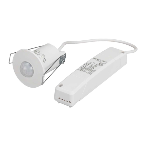
CEILING MOUNT INDOOR OCCUPANCY SENSOR
SPECIFICATION:
1. Power Supply: 220V-240V ~ 50Hz.
2. Time adjustment:
3. Lux adjustment: "Light level" sensing from 5 to 1000 Lux.
4. Range of detection reach up to 8m diameter, minor movement within 4m diameter. Refer to
the figure 1.
5. Load:
Max. 2000W, 250VAC (cosθ=1)
Max. 1000W AC Halogen, 250VAC
Max. 1000W, 250VAC (cosθ=0.5) (uncompensated)
Max. 1500W, 250VAC (cosθ≥0.9)
22 x (4 x 14W) ; 20 x (2 x 21W) ; 20 x (2 x 24W) ; 15 x (2 x 28W) ; 15 x (2 x 35W)
12 x (2 x 39W) ; 12 x (2 x 49W) ; 10 x (2 x 54W) ; 10 x (1 x 80W)
Max. 300W
10 x 9W ; 10 x 11W ; 10 x 13W ; 10 x 19W ; 10 x 20W ; 10 x 23W ; 10 x 24W
10 x 26W ; 10 x 27W ; 10 x 32W ; 9 x 36W ; 8 x 38W ; 7 x 42W ; 6 x 50W
6 x 55W ; 4 x 80W
LED Max. 300W
10 Qty parallel connection
6. Auto mode/ Test mode/ Manual mode.
DETECTION RANGE:
360°
Ø 4m
Ø 8m
Figure 1
PMSCFMINI
, 30 sec, 1 min, 5 min, 10 min and 30 min, maximum=TEST mode.
2.5m
High
PRODUCT CONTENTS:
1. Motion Sensor unit.
2. Power Box unit.
3. User's manual .
1
Advertisement
Table of Contents

Related Manuals for E-matic PMSCFMINI


Summary of Contents for E-matic PMSCFMINI
- Page 1 PMSCFMINI CEILING MOUNT INDOOR OCCUPANCY SENSOR SPECIFICATION: 1. Power Supply: 220V-240V ~ 50Hz. 2. Time adjustment: , 30 sec, 1 min, 5 min, 10 min and 30 min, maximum=TEST mode. 3. Lux adjustment: “Light level” sensing from 5 to 1000 Lux.
- Page 2 SAFETY INSTRUCTIONS: 1. Installation must be performed by a skilled/competent person who is familiar with the appropriate standards and technical requirements of the appliance and its proper installation. Ensure the supply is disconnected at the distribution board before doing with the electrical wiring.
- Page 3 ADJUSTMENTS: 1. TIME: The time can be set variably from , 30 sec, 1 min, 5 min, 10 min and 30 min. Timer starts counting from the latest detected movement. While there is still movement in the detecting area, the LED indicator will flash once and lighting will remain on and the timer will keep resetting.
- Page 4 CONNECTION TO THE POWER SUPPLY: Important: 1. Note: This sensor must be installed according to local Wiring Regulations and Code of Practice. 2. Ensure the supply is disconnected at the distribution board before doing with the electrical wiring. If any doubt, check the wire with a voltage tester. 3.
- Page 5 However, no responsibility can be accepted by Challenger for any misinterpretation of these instructions. Please contact details E-Matic Energy Management Solutions Distributed by Challenger Security Products 10 Sandersons Way, Blackpool, FY4 4NB Tel: 01253 791888, Fax: 01253 791887 Email: enquiries.ematic@adivision.co.uk...
Need help?
Do you have a question about the PMSCFMINI and is the answer not in the manual?
Questions and answers