Table of Contents
Advertisement
Advertisement
Table of Contents

Related Manuals for LSIS LSPV Series


Summary of Contents for LSIS LSPV Series
- Page 1 LSPV Solar Inverter User Manual LSRP-T010L/T013L/T017L/T020L...
-
Page 2: Table Of Contents
Table of Contents Safety-Related Guidelines for LSPV inverter ................3 Introduction ........................3 Explanations ........................3 Risks Involved in Improper Use ..................4 General Information ......................5 Protection against Touching Electrical Parts ..............5 Protection against Magnetic or Electromagnetic Fields during Operation and Assembly Protection against Touching Hot Parts ................ - Page 3 Turn on the Device......................26 Setting the Country Code and the Menu Language ............. 27 Activating the Device ....................29 Navigation on the Control Panel ................... 31 Password Entry......................32 Menu Structure ......................35 ENS Test........................43 Troubleshooting........................45 Self-test Error Messages ....................45 Transient Failure ......................
-
Page 4: Safety-Related Guidelines For Lspv Inverter
You should also study the safety-related guidelines and all other user instructions each time before you start working on this device. Should you have no user information regarding this device, refer to LSIS. Ask for the documents to be sent immediately to those responsible for safe operation of the device. -
Page 5: Risks Involved In Improper Use
1.3 Risks Involved in Improper Use High electric voltage and high working current! Risk of death or severe personal injury by electric shock! DANGER High electric voltage because of incorrect connection! Risk of death or personal injury by electric shock! WARNING High leakage current! Make absolutely sure you establish connection to ground before con-... -
Page 6: General Information
1.4 General Information • Failure to observe these specifications could void your warranty! • The operating and maintenance instructions as well as safety-related guidelines must be read before commissioning. • Proper and correct transport, storage, assembly and installation, as well as care in operation and maintenance, are prerequisites for optimal and safe operation of the device. -
Page 7: Protection Against Magnetic Or Electromagnetic Fields During Operation And Assembly
High voltage! Risk of death or severe personal injury by electric shock! ⇒ The LSPV inverter may only be installed by qualified specialists. Fur- thermore, the installer must be licensed by responsible power suppliers. ⇒ Only trained and qualified personnel specialized in electrical equipment are allowed to operate, maintain and/or repair the LSPV inverter. -
Page 8: Protection Against Touching Hot Parts
1.7 Protection against Touching Hot Parts Surfaces of the housing can be hot! Risk of injury! Risk of burns! ⇒ Do not touch parts of the housing that are close to heat sources! Risk of burns! ⇒ Let the device cool down for 15 minutes before touching the surface of its housing. -
Page 9: Protection When Handling And Assembling
Do not dispose of the SOLARVERT inverter with normal domes- tic waste. Note: The LSPV inverter complies with the RoHS Directive. That means that the device can be delivered to local sites for the disposal of household appliances. LSIS takes the PV inverter completely back. Please contact the Service! -
Page 10: Description Of Lspv Inverter 010K To 020K
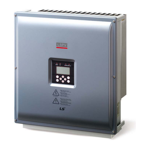
2 Description of LSPV inverter 010K to 020K 2.1 Description of the Device The LSPV inverter is a three-phase solar inverter without a transformer, which has a particularly high efficiency at any operating point and is suitable for the connection of a PV generator with a power of 11kW up to 21.1 kW. -
Page 11: Scope Of Delivery Of The Lspv Inverter 010K To 020K
2.2 Scope of Delivery of the LSPV inverter 010K to 020K The scope of delivery of the LSPV inverter includes a wall-mounting bracket and an enclosed bag 0030532 containing: 1 x 5-pin contact insert, IP67, VC-TFS5-PEA 1 x adapter housing, IP67, VC-K-T3-R-M25-PLOMB 2 x 4-pin male connectors, SACC-M12MS-4SC SH =>... -
Page 12: Block Diagram Of The Lspv Inverter 010K To 020K
2.4 Block Diagram of the LSPV inverter 010K to 020K Figure 3 Block diagram of the LSPV inverter 010K to 020K 1) DC overvoltage protection, type 3 2) AC overvoltage protection, type 3 2.5 Solar Inverter DC Connector The PV generator may not exceed the following operational characteristics under any circum- stances! Device type 010K... - Page 13 MC4 closure caps. By Not observing these requirements the IP65 protection class can not be guaranteed! Both caps (+/-) can be ordered at any time under the part no. 0028991 and 0028992 from LSIS. Figure 5 PV generator connector LSPV inverter 017K to 020K...
-
Page 14: Reverse Current Through Defective Modules
3 PV connecting lines inputs 1, 3 and 5 or inputs 2, 4 and 6 4 PV connecting lines inputs 1, 3, 5 and 6 or inputs 2, 3, 5 and 6 If several PV connecting lines are available, the connections can be made as desired. When using the solar inverter without transformer, do not ground the positive or negative pole of the PV generator! WARNING... -
Page 15: Control Panel
2.7 Control Panel The graphical user interface which is integrated on the front of the device and comprises 128 x 64 pixels can be used to display the development of interesting data, such as the feed power. The parameters required are selected and entered on the 8-key control panel. The control panel is illu- minated on pressing a key and turns dark automatically. -
Page 16: Installation
3 Installation 3.1 Unpacking the Device The inverters are loaded at their head and packed upside down facilitate transport. You will there- fore see the bottom side of the device (connectors) after having opened the package. Take the device at the two holding grips that are visible on the side and remove it from the packaging. When being unpacked, the device keeps the packaging grid locked in place on its housing. - Page 17 • Mount the device at an appropriate distance from combustible materials. • We recommend that you mount the device at eye level to ensure optimum user comfort. • Owing to its protection type (IP65), the device can also be mounted in outside areas. Note: To ensure protection class IP65, only use the male and female connectors provided for connecting the LSPV inverter and connect...
-
Page 18: Transport
40 °C while they are in a de-energized state. If the storage time of two years has been exceeded, please contact the LSIS Service before connecting the LSPV inverter to your system! 3.5 Mounting the LSPV inverter 010K to 020K Mount the inverter by means of the self-centering wall-mounting plate which is included in the scope of delivery. -
Page 19: Connectors On The Device
Any failure to observe these requirements may result in a malfunction of the device or may even cause severe personal injuries through crushing, shearing, cutting, striking, or fire! CAUTION When designing the attachment of the wall-mounting plate, take the weight of the LSPV inverter of 40 kg into account. -
Page 20: Power Connection
3.7 Power Connection Risk of electric shock and fire caused by high leakage current! Before connecting the device to the supply circuit, establish a ground connection by means of the labeled ground stud! CAUTION The power connection has to be connected with a 5 wire cable. For security reasons, protective conductor PE must be connected in any case. -
Page 21: Power Supply Line
Note: When using wire end ferrules with isolating collar, make sure you do not introduce the insulation of the wire end ferrule into the clamping area of the terminal. Figure 11 Power connection 3.8 Power Supply Line Select the cross-section of the power supply line such that line losses are as low as possible. •... -
Page 22: Grid Line Inductance
3.9 Grid line inductance For better efficiency, large line cross-sections and single wire cables are increasingly used for power supply lines, especially if local conditions require long supply lines. The considerable line lengths between LSPV inverter and the transformer station result in a high cable inductance and therefore an increased line impedance. -
Page 23: Grounding
3.10 Grounding Risk of electric shock! The LSPV inverter must be connected to the ground stud. Otherwise, a voltage gradient may develop, which may result in electric shock! CAUTION The LSPV inverter features a threaded bolt below the power supply port on the connection side for additional grounding. -
Page 24: Dc Connecting Line
Live PV strings can be under lethal voltages. ⇒ Before connecting the PV strings, verify that the open circuit voltage does not exceed 50 V. WARNING • The DC connection is effected with MC4-plugs and sockets Ensure that you use DC connectors which are suitable for the particular cable diameter. -
Page 25: Interface Port Rs485
3.14 Interface Port RS485 RS485 OUT RS485 IN Pin 1 Bus termination+ Pin 1 Reference + Pin 2 RS485+ OUT Pin 2 RS485+ IN Pin 3 RS485- OUT Pin 3 RS485- IN Pin 4 Bus termination – Pin 4 Reference – * Bus termination (wire jumper) •... -
Page 26: Relay Port
• Ready-made IP20 cable on IP67 plug: Phoenix Contact VS-04-2X2X26C7/7-67B/SDA, part no. 1653922 for 5 m. Phoenix Contact VS-04-2X2X26C7/7-67B/SDA, part no. 1653919 for 2 m. • Ethernet Plug contained in the enclosed bag. Please use an Ethernet cable with S/FTP design (screened foiled twisted pair). 3.15 Relay Port Normally open contact Pin 1... -
Page 27: Commissioning
4 Commissioning Before commissioning the LSPV inverter, be sure the following steps have been completed: • Confirm the correct power supply connection • Confirm the correct connection of PV strings • Confirm that connectors are protected such that they cannot be pulled off inadvertently Risk of electric shock! ●... -
Page 28: Setting The Country Code And The Menu Language
4.2 Setting the Country Code and the Menu Language The country code defines the country-specific network monitoring parameters. The menu language is automatically set when the country code is selected. Thereafter, the menu lan- guage can be selected as desired at any time, independent of the country code set in the menu. - Page 29 1. Use the “▲” and “▼” keys to select the country code which is specific for your country and your location. - When you select the country code, you automatically select the menu language at the same time. - The menu language can be changed in the menu at any time. 2.
-
Page 30: Activating The Device
5. Press “ “ to confirm. 6. Use the “▼” and “▲” keys to select the desired menu language. 7. Press “ " to confirm. The menu switches to the language selected. The display will be empty at first. 8. Press “ESC” to return to the menu. 4.3 Activating the Device •... - Page 31 • Initializing has been completed: The "READY" status LED emits steady light • Display: Feed power in watts (W) Line voltage in volts (V) Solar cell voltage in volts (V) Switched off Figure 17 Device activation display • Power-up starts if the solar cell voltage is >350 volts: The "READY"...
-
Page 32: Navigation On The Control Panel
Press F1 key to open menu. Use ▼ and / ► arrow keys to select the „Configuration“ item. Use ▼ arrow key to select menu item to set “time/date" / ► Use ►◄ arrow keys for successive setting of day, month, year hour, minute, and second. Press key to confirm. -
Page 33: Password Entry
4.5 Password Entry For the configuration and parameterization often the customer password is required! Password entry as follow: Please enter in the following order (5.) (4.) (3.) (2.) (1.) The customer password is: 72555 Basic screen display: Figure 19 Operating mode display PAC = current feed power UAC = line voltage UDC = solar cell voltage in volts (V) - Page 34 Press the ◄ arrow key once to display the development of the day's feed power. Figure 20 "Today's" feed power display Press the ▼ arrow key to display the development of the previous days. Figure 21 "Yesterday's" feed power display Press the ESC key to return to the basic screen display.
- Page 35 Press the ►arrow key, then the ▼arrow key to display the development of standardized yield data. Figure 23 Standardized yield data display Press the ESC key to return to the basic screen display. Input of standardized data: To obtain the standardized yield data, press the F2 key and enter the connected PV generator power under parameter P1155 as follows: keys:◄►: Press the ◄...
-
Page 36: Menu Structure
4.6 Menu Structure The menu structure serves as a support to change to the individual information displays and setting displays. Legend: Legend Backward and backward to menue Backward Confirmation Arrow key right/ left Arrow key op/ down... - Page 37 Menu guide Analysis Analysis Yield absolute Actual values Yield absolute Day: 41.7 kWh Failure memory Yield normalized Month: 1322.0 kWh Configuration Year: 5083.4 kWh Device information Total: 5083.4 kWh Oper. hr: 422.3 h F1-Menue F1-Menue F1-Menue Analysis Yield normalized Yield absolute Day: 2.8 kWh Yield normalized...
- Page 38 Failure memory Failure memory F02 Parameter error F02 Parameter error F03 Sytem restart F03 Sytem restart F04 Sytem restart F04 Sytem restart 21.10.2009 13:56:24 0X00D0003 F05 Sytem restart F05 Sytem restart F06 Sytem restart F06 Sytem restart F1-Menue F1-Menue Analysis Configuration čeŝtina Actual values...
- Page 39 See:*2 Configuration IP- address Communication Ethernet USS- address 192.168 0.123 Protocol address Subnet mask F1-Menue F1-Menue Configuration Subnet mask Communication Ethernet USS- address 255.255.254. 0 Protocol IP-address Subnet mask F1-Menue F1-Menue Configuration Standard gateway Communication Ethernet Protocol 10.104.120. 1 IP- address Subnet mask Standard gateway F1-Menue...
- Page 40 Configuration Date / Time Languages Communication Date / Time 330.10.2009 14:02:32 Portal settings Extended Password F1-Menue F1-Menue Configuration Configuration Activation Languages Portal settings Communication Activation Date / Time Send configuration Portal settings Server IP Extended Server Port Password Portal Testfunction F1-Menue F1-Menue F1-Menue...
- Page 41 Configuration Configuration Configuration Languages Extended Extended Communication XModem Update XModem Update Date / Time Clear data logger Yes – Update ! Portal settings Numerical list Extended ENS -Test Password F1-Menue F1-Menue F1-Menue See:*8 Configuration Configuration Extended Extended XModem Update Clear data logger Clear data logger Yes –...
- Page 42 Configuration Input password Languages Communication Date / Time Portal settings Extended Password F1-Menue F1-Menue Analysis Device information Version number Actual values Version number Failure memory Country Configuration Current language Device information Device type RFP-800R015-25-6-S Seriennummer F1-Menue F1-Menue F1-Menue Device information Country Version number Country...
- Page 43 Detailed explanations *1. Communication via USB USS address: Input 1 – 31 This address is required for communicating with LSPV inverter via USB. Note: If you change this parameter (address) and wish to save it, you must restart LSPV inverter! The new address will only be active thereafter.
-
Page 44: Ens Test
*5. Sending Config Input 0 or 1 0 = no Config data in the waiting queue 1 = Config is sent. *6. Server IP Display of the IP address *7. Server port Display of the port number of the web server. *8. - Page 45 Carrying out the ENS Test: • Set P0900 to "1" starts the ENS test • P0901 shows the progress of the ENS test • P0908 informs about the frequency ramp (in mHz/s) • P0902 shows the development of the simulated frequency •...
-
Page 46: Troubleshooting
5 Troubleshooting 5.1 Self-test Error Messages After the initialization routine, the system runs through a self-test. The individual parts of the system, such as firmware and dataset, are checked and data is read in from the power control board. If an error continues to be ascertained, possible Remedial measures must be taken according to the type of error. -
Page 47: List Of Fault Messages
5.5 List of Fault Messages Error Error message Description Action code Step-up converter of posi- Wait until the controller 0A0001 Controller voltage 1 tive DC link has re-stabilized. failed to control Step-up converter of nega- Wait until the controller 0A0002 Controller voltage 2 tive DC link has re-stabilized. - Page 48 Error Error message Description Action code Possibly caused by switch- Detecting line ing actions on the net. Re- Undervoltage 0A0010 undervoltage measure line voltage. phase on outside conductor Service if line voltage is within normal range Check system frequency Detecting a power error and line voltage.
- Page 49 Error Error message Description Action code Insulation error detector of Check insulation of the sys- 0A010C PV isolation LT power section tem. AFI sensor failed; check Fault current detector of P.C.B. contacting; replace 0A010D Grid iso LT PEF power section through Service if neces- sary Hardware switchoff of...
- Page 50 Error Error message Description Action code Timeout of balancing of 0A011D Activation LT4 Acknowledge error lower DC links Timeout of uploading proc- 0A011E Activation LT Acknowledge error Problem in communication Acknowledge error. 0x0A0120 Communication LT between the control and the Contact the Service if the power section error occurs repeatedly.
- Page 51 Error Error message Description Action code Restart if DC power has increased. 0x0E0013 Precharge Precharge failure Contact the Service if the error occurs repeatedly. Precharge contac- 0x0E0015 Precharge cont. failure Contact the Service. 0x0E0016 DC main contactor DC contactor failure Contact the Service.
- Page 52 Error Error message Description Action code DC current regis- Failure of DC current con- 0x0E0027 Contact the Service. tration verter Input the country code at Invalid country of the initial installation. (It can 0x0E0028 Country code is missing be changed only service personnel.) Power supply fault 0x0E0029...
- Page 53 Error Error message Description Action code Measure 3 AC voltages SWM power supply Space vector modulation against the N conductor. 0x0E0032 fault fault (internal) Reset and restart. Contact the Service if necessary. Check the DC voltage. En- 0x0E0033 DC voltage 3 DC solar voltage too low sure correct interconnection of strings.
-
Page 54: Maintenance
6 Maintenance The cooling of the LSPV 010K - 020K is done exclusively through the natural convection. For safe operation according to the environment, the cooling fins on the heat sink should be checked against dirt and if necessary clean up of dust / dirt. The DC switch is designed for a very long life but it is advised to do some simple yearly mainte- nance. -
Page 55: Technical Data
7 Technical Data 7.1 LSPV inverter 010K to 020K Type 010K 013K 017K 020K DC data 11 kW 13.6 kW 18.1 kW 21.1 kW Max. PV power 380 – 850 V 420 – 850 V 445 – 850 V 480 – 850 V MPPT range 1000 V Max. - Page 56 Type 010K 013K 017K 020K CE (UL and CSA in preparation) Certificate Interference immunity EN 61000-6-2; 2005 Environmental classification 4K4H according to DIN IEC 721-3-3 Acc. to VDE 0126-1-1 Mechanics IP65 as per EN 60529 Type of protection Dimensions Width / Height / Depth 535 mm / 601 mm / 277 mm 39 kg Weight...
-
Page 57: Contact
8 Contact You should have the following data at hand: • Exact description of the error and if possible HEX code of the error (P0017.00). • Data from the type plate:... -
Page 58: Certificates
9 Certificates The following certificates • EC Declaration of Conformity • VDEW Declaration of Conformity • Clearance Certificate can be downloaded from the LSIS homepage www.lsis.biz. - Page 59 - For the product discontinued, the repair service will be provided with charge for five years from the date discontinued. ■ Waiver of the warranty for the mechanical loss, etc. LSIS Co., Ltd. doesn't bear any responsibility to indemnify indirect, special, incidental, or consequential loss (including the indemnification of sales loss, loss profit, etc.
- Page 60 Tel: 84-4-882-0222 Fax: 84-4-882-0220 e-mail: srjo@lsisvina.com Tel: 86-532-8501-6568 Fax: 86-532-583-3793 e-mail: lirj@lsis.com.cn ※ LSIS constantly endeavors to improve its product so that LSRP Series/2011.05 Information in this manual is subject to change without notice. ⓒ LSIS Co., Ltd 2011 All Rights Reserved.
Need help?
Do you have a question about the LSPV Series and is the answer not in the manual?
Questions and answers