Table of Contents
Advertisement
Quick Links
Advertisement
Table of Contents

Subscribe to Our Youtube Channel
Related Manuals for LSIS LSRP-T100LT


Summary of Contents for LSIS LSRP-T100LT
- Page 1 LSPV Solar Inverter User Manual LSRP-T100LT/T160LT...
-
Page 2: Table Of Contents
Table of Contents Safety Notes for LSPV Inverter ....................3 Introduction......................... 3 Explanations ....................... 3 Risks Involved in Improper Use.................. 4 General........................5 Protection Against Touching Electrical Parts ............. 6 Protection against Magnetic or Electromagnetic Fields during Operation and Assembly ............................ - Page 3 Control and Communication..................25 4.10 Operator’s Terminal Strip X54.................. 29 4.11 Operating pad......................30 4.12 Internal Data Logger....................30 Putting into Operation......................31 Preconditions......................31 Switching On ......................31 Setting the Country Code and the Menu Language..........31 Activating the Device ....................34 Navigation via the Operating Pad................
-
Page 4: Safety Notes For Lspv Inverter
This also applies to the safety instructions and all other user instructions before performing any work on this unit. Should you have no user information regarding the unit, refer to LSIS. Ask for the documents to be sent immediately to those responsible for safe operation of the unit. -
Page 5: Risks Involved In Improper Use
Risks Involved in Improper Use High electric voltage and high working current! Risk of death or severe bodily injury by electric shock! DANGER High electric voltage because of incorrect connection! Risk of death or bodily injury by electric shock! WARNING Large leakage current! Make sure to connect to grounding before connecting to the power supply circuit! -
Page 6: General
General • LSIS does not assume any liability for damages caused by failure to observe the warnings given in these operating instructions. • Before first operation, thoroughly read through the operation and maintenance instructions and the safety notes. • Proper and qualified transport, storage, assembly and installation, as well as conscientious operation and maintenance are preconditions for faultless and safe operation of this unit. -
Page 7: Protection Against Touching Electrical Parts
Protection Against Touching Electrical Parts Note: This section only concerns units and unit components that are under voltages greater than 50 Volts. It is dangerous to touch parts that are under voltages greater than 50 Volts, since this could result in electric shock. -
Page 8: Protection Against Touching Hot Parts
Magnetic and electromagnetic fields exist in the immediate vicinity of power-carrying conductors and can be a serious danger to people with cardiac pacemakers, metallic implants, or hearing aids. Health risk for persons with cardiac pacemakers, metallic implants, or hearing aids in the immediate vicinity of electrical equipment! ⇒... -
Page 9: Protection When Handling And Assembling
Note: We do not assume any liability for an incorrectly set country code! The pertinent regulations of the responsible power supplier must be observed! Protection when Handling and Assembling In unfavorable conditions, handling and assembling certain parts and components in an improper way can cause injuries. -
Page 10: General
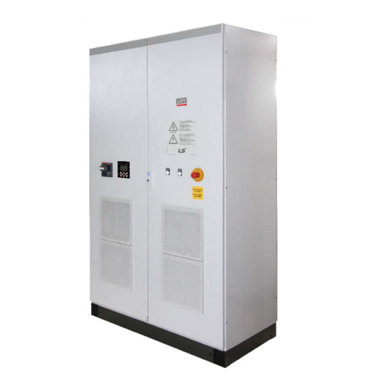
General You have made a good choice in purchasing a LSPV inverter. In order to guarantee reliable operation, all connections must be made correctly. The information you will need for this is given in the following chapters and in the safety notes. Figure 1: View of the LSPV inverter control cabinet Transport... -
Page 11: Conditions For Installing
Conditions for Installing Note: Failure to observe the below conditions might render the warranty invalid. 2.3.1 Environment The floor beneath the cabinet must be strong enough to bear the great weight. For weights, see technical data. Adherence to the minimum passage widths when installing in electrical operation rooms. See DIN VDE 0100 Parts 729 and 731. - Page 12 IP24 Housing Air duct Filter mat Filter mat Filter mat min. 1000 max.
- Page 13 Abutting Installation Air duct REFU REFU Spaced Installation Air duct Air duct REFU REFU...
-
Page 14: Tilting The Control Cabinet Roof
2.3.3 Tilting the Control Cabinet Roof In order to guarantee sufficient cooling of the control cabinet components, the roof of the cabinet must be tilted before the system is put into operation. To do this, proceed as follows: 2.3.4 Removing the Transport Eyelets First remove the four transport eyelets on the control cabinet roof. -
Page 15: Loosening The Bracket Bolts
2.3.5 Loosening the Bracket Bolts Open the control cabinet doors and loosen the fastening bolts on the roof brackets at the top of the cabinet frame. Figure 4: Right bracket bolts, roof folded down Figure 5: Left bracket bolts, roof folded down 2.3.6 Tilting the Roof After having loosened the roof bracket fastening bolts, tilt the roof (see figure 6)! Figure 6:... -
Page 16: Tightening The Bracket Bolts
2.3.7 Tightening the Bracket Bolts Now tighten the bracket bolts firmly Figure 7: Right bracket bolts, roof tilted up Figure 8: Left bracket bolts, roof tilted up Risk of injury! Secure the roof against falling down again! CAUTION... -
Page 17: Pv Generator Requirements
PV Generator Requirements 2.4.1 DC Connection to the Solar Inverter The PV generator must not exceed the following operational characteristics under any circumstances! Max. DC voltage 850 V Max. DC current 240 A 2.4.2 Reverse Current Due to Module Defects Reverse currents are fault currents that only occur in PV systems comprising strings in parallel. -
Page 18: Description Of The Unit
Description of the Unit The LSPV inverter consists of a control cabinet in which all components required for function and safety are installed. That means the only work required for installation is to connect the mains feeder, the auxiliary power and the PV generator. The following section describes the components of the AC inverter and DC part contained in the cabinet. -
Page 19: Block Diagram
Block Diagram Block diagram of LSPV inverter ® Figure 9: 1) Circuit-breaker (-Q10) 2) Lightning protection (-F10) 3) EMV – mains filter (-V10) 4) Supply disconnection contactor (-Q11) 5) Three-phase transformer (-T10) 6) Inverter (-T20) 7) Contactor (-Q22) 8) Contactor (-Q23) 9) Overload protection (-F20) 10) EMV –... -
Page 20: Electricel Connection
Electricel Connection Warning and Notices Fatal electric shock from live parts under more than 50 V! ⇒ LSPV inverter units operate at high voltages. They may only be worked on when completely de-energized! ⇒ They may only be worked on by qualified personnel! ⇒... -
Page 21: Overview Of The Open Control Cabinet
Overview of the OPEN Control Cabinet Figure 10: Overview of the LSPV inverter connections... -
Page 22: Line Cross-Sections
Line Cross-Sections Connection point Minimum cross-section Connectable cross section Auxiliary supply 1.5 mm² (rigid) 4 mm² (rigid) operator's terminal strip X54 0.75 mm² (flexible) 2.5 mm² (flexible) Power connection 70 mm² 95 mm² PV generator 95 mm² 2 x 150 mm² The DC current must be limited by the operator to 240 A: Damage to the unit due to excessive DC current! The DC current must never exceed 240 A under any circumstances,... -
Page 23: Power Connection
Power connection The mains power is attached to terminal block X01; the position of the terminal block is shown in Figure 10:. The following connection order must be strictly followed. Connection order: Bolt M12 x 30 Spring washer Terminal bar Cable eye for feed line Spring washer... -
Page 24: Pv Generator
PV generator The PV generator is attached to terminal block X02; the position of the terminal block is shown in Figure 3. The following connection order must be strictly followed. Connection order: Bolt M10 x 30 Spring washer Terminal bar Cable eye for feed line Spring washer... - Page 25 If PV systems are grounded, personnel protection measures must be taken! Work on the device may only be carried out after safety disconnecting of all poles on the AC and DC sides! WARNING Detailed information can be found under www.lsis.biz...
-
Page 26: Control And Communication
Control and Communication The connections for control and communication are made directly on the SR27000B control unit over the corresponding plugs. Plan of Terminals SR27000B X10 / 11 Operating pad connection MMC (not supported) Ethernet LEDs for status display RED: Fault X14 / 15 RS485 Yellow: Operation... - Page 27 Description of Data Interfaces Operating pad connection Terminal Designation Comment +5V output Isolated! RS485+ IN Fixed setting! RS485- IN Baud rate: 115.2 kBaud Parity: Even Stop bits. Bus termination+ Data bits: RS485+ OUT Protocol: USS, RS485- OUT 4/6 words Address: Bus termination- Figure 12: Operating pad connection Ethernet, interface for LS Web Server...
- Page 28 RS485; interface for external monitoring Terminal Comment Designation Isolated! RS485+ IN Fixed setting! RS485- IN Baud rate: 115.2 kBaud IN reference Parity: Even Stop bits. Bus termination+ Data bits: RS485+ OUT Protocol: USS, 4/6 words RS485- OUT Address: Bus termination- The RS485 interface supports the USS protocol (universal serial interface protocol), which can be used for transmission of data, e.g.
- Page 29 Digital/Analog IO Terminal Comment Designation Function Digital Input 1 Digital Input 2 Malfunction Digital Input 3 Transformer temperature OK Digital Input 4 Enable solar generator Digital inputs/outputs with isolation Digital input 5 Enable power supply Level according to EN61131 Type 2 (SPS compatible) Digital input 6 Malfunction reset...
-
Page 30: Operator's Terminal Strip X54
CAN bus; currently not functional! Designation Comment Terminal CAN-OPEN protocol CAN bus 4.10 Operator’s Terminal Strip X54 The following control terminal bar functions are available to the operator: Default External signal LSPV inverter function description Internal signal setting +24 V DC supply Mains disconnection with Q10 24 VDC / 3 A 0 V DC supply... -
Page 31: Operating Pad
4.11 Operating pad The integrated 128x64 pixel graphic display on the front displays the course of interesting data such as feed power. The required parameters can be selected and entered via the 8-key operating pad. The operating pad lights up when the first key is pressed and turns dark again after 5 minutes. Status LED Display the menu. -
Page 32: Putting Into Operation
Putting into Operation Preconditions In order to commission the LSPV inverter properly and safely, the below requirements must be met. Before connecting the power supply and PV generator, the following must be verified: All connections were made according to the connection diagram. The ground wire for the mains feed-in and auxiliary power supply must be connected. - Page 33 Cancellation of the operating licence! If the LSPV is operated with a wrong country code, the electric supply company may cancel the operation licence. It is not allowed to put the LSPV into operation before the overall system CAUTION complies with the national rules and safety regulation of the application. Note: We do not assume any liability for any negative consequences of an incorrectly set country code!
- Page 34 Accepting the country code The display will show a safety prompt asking you whether you wish to accept the country code. After having accepted the country code, it is no longer possible to change it. 1. Confirm the country code only if you are absolutely sure. - If you are not sure, press "ESC”...
-
Page 35: Activating The Device
Activating the Device • Make sure that mains voltage is present at the unit. This can be achieved by installing the external mains fuse or switching on the circuit breaker. • Then switch the DC isolating switch on the inverter to ON. Provided that the solar modules are exposed to sufficient sunlight and that there are no errors or failures, the device undergoes the following sequence of operations which you can follow on the display of the operating pad:... -
Page 36: Navigation Via The Operating Pad
• Power-up starts if the solar cell voltage is >460 volts “READY” status LED is lit, “ON” status LED flashes • Display: Solar cell voltage in volts (V) Activating This process can take up to one hour if the device is commissioned; during normal operation, it takes up to 3 minutes. - Page 37 Display the menu ◄►: Function in the menu: navigation through the menu level (previous menu, next menu) Function while parameters are edited: digit to the left, digit to the right (decade jump) ▲▼: Select the menu level (level up, level down) ESC: Acknowledge failures and exit from menu-lvel, exit from input level without acknowledge Confirm the selected menu and entered data...
- Page 38 Figure 19: Feed power display “Yesterday” Press the ESC key to return to the basic screen. Yield data display Press the ► arrow key once to display the absolute yield data and the operating hours accrued so far. Figure 20: Yield data display Standardized yield data display Press the ►arrow key, then the ▼arrow key to display the development of standardized yield data.
-
Page 39: Menu Structure
◄► keys: Press the ◄ key => selects the digit to the left of the decimal point. Press the ► key => selects the digit to the right of the decimal point. ▲ key: Whenever you press this key, the number at the digit selected is incremented by 1. - Page 40 Display functionality Analysis Analysis Yield absolute Actual values Yield absolute Day: 41.7 kWh Failure memory Yield normalized Month: 1322.0 kWh Configuration Year: 5083.4 kWh Device information Total: 5083.4 kWh Oper. hr: 422.3 h F1-Menue F1-Menue F1-Menue Analysis Yield normalized Yield absolute Day: 2.8 kWh Yield normalized...
- Page 41 Failure memory Failure memory F02 Parameter error F02 Parameter error F03 Sytem restart F03 Sytem restart F04 Sytem restart F04 Sytem restart 21.10.2009 13:56:24 0X00D0003 F05 Sytem restart F05 Sytem restart F06 Sytem restart F06 Sytem restart F1-Menue F1-Menue Analysis Configuration čeŝtina Actual values...
- Page 42 See:*2 Configuration IP- address Communication Ethernet USS- address 192.168 0.123 Protocol address Subnet mask F1-Menue F1-Menue Configuration Subnet mask Communication Ethernet USS- address 255.255.254. 0 Protocol IP-address Subnet mask F1-Menue F1-Menue Configuration Standard gateway Communication Ethernet Protocol 10.104.120. 1 IP- address Subnet mask Standard gateway F1-Menue...
- Page 43 Configuration Date / Time Languages Communication Date / Time 330.10.2009 14:02:32 Portal settings Extended Password F1-Menue F1-Menue Configuration Configuration Activation Languages Portal settings Communication Activation Date / Time Send configuration Portal settings Server IP Extended Server Port Password Portal Testfunction F1-Menue F1-Menue F1-Menue...
- Page 44 Configuration Configuration Configuration Languages Extended Extended Communication XModem Update XModem Update Date / Time Clear data logger Yes – Update ! Portal settings Numerical list Extended ENS -Test Password F1-Menue F1-Menue F1-Menue See:*8 Configuration Configuration Extended Extended XModem Update Clear data logger Clear data logger Yes –...
- Page 45 Configuration Input password Languages Communication Date / Time Portal settings Extended Password F1-Menue F1-Menue Analysis Device information Version number Actual values Version number Failure memory Country Configuration Current language Device information Device type RFP-800R015-25-6-S Seriennummer F1-Menue F1-Menue F1-Menue Device information Country Version number Country...
- Page 46 Detaiedl explanations *1. Communication via USB USS address: Input 1 – 31 This address is required for communicating with LSPV inverter via USB. Note: If you change this parameter (address) and wish to save it, you must restart LSPV inverter ! The new address will only be active thereafter. Protocol: Input 1 USS and RPC protocol...
-
Page 47: Ens Test
*5. Sending Config Input 0 or 1 0 = no Config data in the waiting queue 1 = Config is sent. *6. Server IP Display of the IP address *7. Server port Display of the port number of the web server. *8. -
Page 48: Password Entry
• P0903.00 shows the frequency value having caused turnoff at the lower limit • P0903.01 shows the frequency value having caused turnoff at the upper limit • P0909 informs about the voltage ramp (in mV/s) • P0904 shows the development of the simulated voltage •... -
Page 49: Troubleshooting
Troubleshooting All work on the LSPV inverter may only be performed when it is completely de-energized, i.e. The LSPV inverter must be definitely and safely isolated from the PV generator. To achieve this, press the EMERGENCY STOP button; this will open DC circuit breakers Q20 and Q21 and isolate the PV generator from the LSPV inverter . -
Page 50: Fault Acknowledgement
Fault Acknowledgement After a shutdown due to a fault, the unit remains locked against reactivation until the fault is acknowledged. It is not possible to acknowledge the fault while the cause of the fault still exists. Once the cause of the fault has been eliminated, the fault can be acknowledged as follows. The signals: •... -
Page 51: List Of Fault Messages
6.5 List of Fault Messages Error Error message Description Action code Although there is no error, 000000 Error management Please restart the system. the device is in the "fault" state 1. Please restart the system. Invalid parameter file; a 030002 Parameter error 1 2. - Page 52 Error Error message Description Action code Possibly caused by switching actions on the net. 1. Wait until the situation has eased or Line overvoltage is detected on outside remeasure the line voltage. 0A000F Overvoltage Phase conductor (ENS, control section) 2. Contact the network operator if the line voltage fails to be within normal ranges.
-
Page 53: Maintenance
Maintenance 7.1 Maintenance Instructions To ensure reliable operation of the LSPV inverter, maintenance measures must be taken at regular intervals. We also offer a service maintenance contract. Maintenance measures may only be taken by trained and qualified staff. According to the technical safety notes contained in this documentation, only persons having the specialist knowledge and authorization to commission and ground devices, systems and electric circuits according to current technical safety standards are considered to be qualified staff. - Page 54 Action to be taken Maintenance interval Check and, if necessary, replace the indicator lamps. 12 months Check and, if necessary, replace the warnings (labels). 12 months * Shorter maintenance intervals might be necessary (depending on the location and ambient conditions).
-
Page 55: Technical Data
Technical data Type LSPV inverter 100K DC Data 115 kW Max. PV power 460...800 V MPPT range 850 V Max. DC voltage 240 A Max. DC current Fast, precise MPP tracking MPP tracking IEC 61643-21 / EN 61643-22 - type 2 Internal overvoltage protection AC Data 100 kW... - Page 56 Type LSPV inverter 100K 1200 mm / 2000 mm / 600 mm Dimensions Width / Height / Depth 860 kg Weight DC contactor DC disconnection Main switch and main contactor AC disconnection...
-
Page 57: Contact
Contact You should have the following data at hand: • Exact description of the error, and possibly HEX code of the error (P0017.00) • Data from the type plate... -
Page 58: Certificates
Certificates The certificates are currently in preparation, and will be made available for download from LSIS website www.lsis.biz when they are ready. - Page 59 - For the product discontinued, the repair service will be provided with charge for five years from the date discontinued. ■ Waiver of the warranty for the mechanical loss, etc. LSIS Co., Ltd. doesn't bear any responsibility to indemnify indirect, special, incidental, or consequential loss (including the indemnification of sales loss, loss profit, etc.
- Page 60 Tel: 84-4-882-0222 Fax: 84-4-882-0220 e-mail: srjo@lsisvina.com Tel: 86-532-8501-6568 Fax: 86-532-583-3793 e-mail: lirj@lsis.com.cn ※ LSIS constantly endeavors to improve its product so that LSRP Series/2011.05 Information in this manual is subject to change without notice. ⓒ LSIS Co., Ltd 2011 All Rights Reserved.
Need help?
Do you have a question about the LSRP-T100LT and is the answer not in the manual?
Questions and answers