Sofar solar HYD 3000-ES User Manual
Energy storage integrated inverter
Hide thumbs
Also See for HYD 3000-ES:
- User manual (50 pages) ,
- User manual (43 pages) ,
- User manual (10 pages)

Related Manuals for Sofar solar HYD 3000-ES


Summary of Contents for Sofar solar HYD 3000-ES
- Page 1 User manual Energy storage integrated inverter Product Model: HYD 3K~6K-ES S h e n z h e n S O FA R S O L A R C o . , L t d .
-
Page 2: Table Of Contents
HYD 3K~6K-ES User manual Contents Preface .......................II 1. HYD-ES inverter Introduction ...............1 2. Safety Notes ....................2 2.1. Safety Notes ..................2 2.2. Installation and Maintenance Notes ............2 2.3. Signs on the inverter ................4 3. Installation ......................5 3.1. Product Overview ................5 3.2. - Page 3 HYD 3K~6K-ES User manual Notice This manual contains important safety instructions that must be followed during installation and maintenance of the equipment. Save these instructions! This manual must be considered as an integral part of the equipment. The manual must always accompany the equipment,even when it is transferred to another user or field.
-
Page 4: Preface
Scope This product manual describes the installation,electrical connections, commissioning,maintenance and troubleshooting of HYD 3K-6K-ES inverters: HYD 3000-ES HYD 3600-ES HYD 4000-ES HYD 4600-ES HYD 5000-ES HYD 6000-ES Keep this manual where it will be accessible at all times. - Page 5 HYD 3K~6K-ES User manual Danger indicates a hazardous situation which, if not avoided, will result in death or serious injury. Danger Warning indicates a hazardous situation which, if not avoided, could result in death or serious injury. Warning Caution indicates a hazardous situation which, if not avoided, could result in minor or moderate injury.
-
Page 6: Hyd-Es Inverter Introduction
HYD 3K~6K-ES User manual 1. HYD-ES inverter Introduction The HYD-ES hybrid inverter is used in PV system with battery storage. Energy produced by the PV system will be optimized for maximum self-consumption. The HYD-ES inverter can work in auto or time-of-use (TOU) mode, charge / discharge the battery when needed. -
Page 7: Safety Notes
HYD 3K~6K-ES User manual 2. Safety Notes Before installation, please make sure you read & understand this manual. The HYD-ES inverter strictly comply with safety rules of design and testing. During the installation, operation and maintenance, operators should abide by local safety regulations. - Page 8 HYD 3K~6K-ES User manual put the HYD-ES inverter/batteries in an airtight or badly ventilated place or cabinet. This can be very harmful to system performance & service life. Keep HYD-ES inverter/batteries away from direct sunshine. Don’t put HYD-ES inverter/batteries close to a furnace or fire. The can lead battery to leak even explode.
-
Page 9: Signs On The Inverter
HYD 3K~6K-ES User manual 2.3. Signs on the inverter There are some symbols which are related to security on the inverter. Please read and understand the content of the symbols before system installation. This symbol indicates a hazardous situation which could result in injuries, if not avoided. -
Page 10: Installation
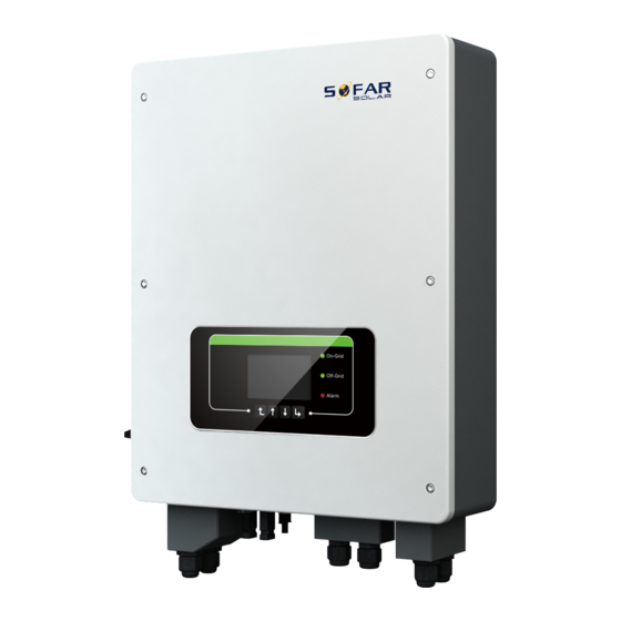
HYD 3K~6K-ES User manual 3. Installation 3.1. Product Overview HYD-ES inverter is 100% strictly inspected before package and delivery. It is forbidden to put the HYD-ES inverter upside down during delivery. Please check the product package and fittings carefully before installation. Caution Fig.3-1 HYD-ES inverter overview Current transformer port/DRM0... -
Page 11: Packing List
HYD 3K~6K-ES User manual 3.2. Packing List Inspect the package and fittings carefully before installation. You should have the following fittings: Table3-1 Components and mechanical parts that should be delivered Picture Description Quantity Inverter 1pcs Mounting Bracket 1pcs AC terminal 6pcs M5 screw 2pcs... - Page 12 HYD 3K~6K-ES User manual 1pcs Communication cable 1pcs NTC×1 (Long-3M) 1pcs PV+ input terminal 2pcs PV- input terminal 2pcs Metal terminals secured to PV+ input power 2pcs cables Metal terminals secured to PV- input power 2pcs cables User Manual 2pcs Warranty card 1pcs —...
-
Page 13: Installation Environment
HYD 3K~6K-ES User manual Quality Certificate 1pcs Outgoing inspection report 1pcs M4X14 Cross round head triple set screw(Only for DC 1pcs switch lock) 3.3. Installation Environment Choose a dry, clean, and tidy place, convenient for installation Ambient temperature range: -25℃ ~ 60℃ ... -
Page 14: Installation Position
HYD 3K~6K-ES User manual Turn the screw to connect rear panel with 4mm Allen Key inverter Crimping tools Used to crimp power cables Multi-meter Used to check grounding Marker pen Used to mark signs Measuring tape Used to measure distances Used to ensure that the rear panel is properly Level installed... - Page 15 HYD 3K~6K-ES User manual — 10 — Copyright © Shenzhen SOFARSOLAR Co., Ltd...
-
Page 16: Mount Hyd-Es Inverter
HYD 3K~6K-ES User manual 3.6. Mount HYD-ES inverter Fig. 3-3 Mount HYD-ES inverter — 11 — Copyright © Shenzhen SOFARSOLAR Co., Ltd... - Page 17 HYD 3K~6K-ES User manual Step 1: Put the mounting bracket properly on the wall, mark these 8 drill holes using a marker pen. Drill 8 holes (drill bit 6mm) on the wall. Step 2: Insert the expansion screw vertically into the hole, note the insertion depth. (not too shallow or too deep) Step 3: Fix the mounting bracket on the wall using bolts &...
-
Page 18: Electrical Connection
HYD 3K~6K-ES User manual 4. Electrical Connection High voltages in power conversion circuits. Lethal hazard of electric shock or serious burns. All work on the PV modules, inverters, and battery systems must be carried out by qualified personnel only. Wear rubber gloves and protective clothing (protective glasses and boots) when working on high voltage/high current systems such as INVERTER Caution and battery systems. - Page 19 HYD 3K~6K-ES User manual Fig. 4-1 Electrical connections Plan A:CT (default) — 14 — Copyright © Shenzhen SOFARSOLAR Co., Ltd...
- Page 20 HYD 3K~6K-ES User manual Plan B:Meter+CT (optional) — 15 — Copyright © Shenzhen SOFARSOLAR Co., Ltd...
-
Page 21: Battery Connection
HYD 3K~6K-ES User manual 4.1. Battery Connection Fig. 4-2 Battery connection (Measure battery wires polarity/voltage before connection) Step 1: Loosen 4 screws (A) using a screwdriver (Fig. 4-2); Step 2: Remove the waterproof cover (B), loosen the cable gland (C), and then remove the stopper (G);... -
Page 22: Inverter Logic Interface Connection
HYD 3K~6K-ES User manual Fig.4-3 Connect Battery&PV connectors 1. Positive metal contact 3. Positive connector 2. Negative metal contact ① 4. Negative connector ② ③ ⑤ ⑥ ④ Disconnect PV connectors ⑦ Before removing the PV positive and negative connectors, ensure that the DC SWITCH is OFF. - Page 23 HYD 3K~6K-ES User manual Step 4: Route Cable terminal through the cable gland, Insert the communication cable into the RJ45 connector; Step 5: Fasten the waterproof cover using 4 screws. Fig.4-4 Logic interface ① ② 1.White and orange 2.Orange 3.White and green 4.Blue 5.White and blue 6.Green...
- Page 24 HYD 3K~6K-ES User manual Green RefGen White and brown Pin7&Pin8 short internal Brown (b)Logic interface for VDE-AR-N 4105:2018-11, is in order to control and/or limit the inverter’s output power. The inverter can be connected to a RRCR (Radio Ripple Control Receiver) in order to dynamically limit the output power of all the inverters in the installation.
- Page 25 HYD 3K~6K-ES User manual Table 4-3 Function description of the terminal Pin NO. Pin name Description Connected to (RRCR) Relay contact 1 input K1 - Relay 1 output Relay contact 2 input K2 - Relay 2 output Relay contact 3 input K3 - Relay 3 output Relay contact 4 input K4 - Relay 4 output...
-
Page 26: Ct / Can / Rs485 / Ntc Connection
HYD 3K~6K-ES User manual Not Connected Not Connected Table 4-6 The inverter is preconfigured to the following RRCR power levels,close is 1, open is 0 Active Power Power drop rate Cos(φ) <5 seconds 100% 4.4. CT / CAN / RS485 / NTC connection Generation and Export Limit Control functions for the inverter are available but require the use of an external measurement device to obtain grid information. - Page 27 HYD 3K~6K-ES User manual coupling (PCC) will be limited to the set Reflux Power limit. Both Hard Anti-Reflux Control and Anti-Reflux Control can be used together. However, when Hard Anti-Reflux control is enabled, Anti-Reflux power limit cannot exceed the Hard Anti-Reflux power limit. The limit value is reported to overload protection.
- Page 28 HYD 3K~6K-ES User manual Fig.4-8 CT / CAN / RS485 / NTC connection ② ① Step 3: Loosen 4 screws (part A) using a screwdriver (Fig.4-8 ① Step 4: Remove the waterproof cover (part B), loosen the cable gland (part C), then remove the stopper (part G) Step 5: Route CT cable through the cable gland, connect CT cable to CT terminal, then insert CT terminal into corresponding ports.
-
Page 29: Grid Connection
HYD 3K~6K-ES User manual Step 7: Connect NTC for lead acid batteries only: Fig. 4-9 NTC connection (Temperature sensor) When the temperature sensor detects that the temperature is higher than 45 ℃, stop charging/display over temperature alarm ID 54, and resume charging discharging below 35 ℃;... -
Page 30: Critical Load Connection (Eps Function)
HYD 3K~6K-ES User manual Fig.4-10 Grid & Load connection Context All the AC output cables used for the inverters are outdoor three-core cables. To facilitate the installation, use flexible cables. The following table lists the recommended specifications for the Breaker. Model 3000-ES 3600-ES... -
Page 31: Wifi/Gprs/Ethernet Module
HYD 3K~6K-ES User manual Fig. 4-11 Change-over Switch connections 4.7. WiFi/GPRS/Ethernet module NOTE:GPRS and Ethernet is optional and is not suitable for all countries . Step1: Remove WiFi/GPRS/Ethernet waterproof cover using screw driver. Step2: Install WiFi/GPRS/Ethernet module. Stpe3: Fasten WiFi/GPRS/Ethernet module using screws. The operation information (generated energy, alert, operation status) of the inverter can be transferred to PC or uploaded to the server via WiFi /GPRS/ Ethernet. -
Page 32: Buttons And Indicator Lights
HYD 3K~6K-ES User manual 5. Buttons and indicator lights Fig 5-1. Buttons and indicator lights 5.1. Buttons Press “back” to the previous screen or enter the main interface. Press “up” to the upper menu option or value plus 1. ... -
Page 33: Operation
HYD 3K~6K-ES User manual 6. Operation 6.1. Double Check Please double check the following before operation. HYD-ES inverter is firmly fastened to the mounting bracket on the wall; PV+/PV- wires are firmly connected, polarity and voltage are correct; BAT+/BAT- wires are firmly connected, polarity and voltage are correct; DC isolator is correctly connected between battery &... -
Page 34: First Time Setup (Important!)
HYD 3K~6K-ES User manual First Time Setup 6.3. HYD-ES inverter should start to operate now. Attention:The following steps for first time start up only 1)Set system time 8)*Set min discharge voltage 2)Set country 9)*Set max discharge current 3)Select battery type 10)*Set min protect voltage 4)*Set battery capacity 11)*Set discharge depth... - Page 35 HYD 3K~6K-ES User manual China Slovakia ZSD AU-VAR CEI0-21 In France AUSGRID Areti Poland Ukraine Horizon Germany BDEW Brazil Australia B Germany VDE Mexico Australia C 0126 Italy CEI0-16 FAR Arrete23 UK-G98 Denmark Tr322 Wide-Range-60 Greece island EU EN50438 Ireland EN504 IEC EN61727 Thailand PEA Korea...
- Page 36 HYD 3K~6K-ES User manual Protective function 47Hz 47Hz 45Hz 45Hz limit value Under- Trip delay frequency 1 time (F<) Maximum disconnectio n time Protective function 52Hz 52Hz 55Hz 55Hz limit value Over- Trip delay frequency 1 time (F>) Maximum disconnectio 0.2s 0.2s 0.2s...
- Page 37 HYD 3K~6K-ES User manual Inverter reactive power level (Q) % supplying supplying of Srated It’s very important to make sure that you have selected the correct country code according to requirements of local authority. Please consult qualified electrical engineer or personnel from electrical safety authorities about this.
- Page 38 HYD 3K~6K-ES User manual “Set max charge current” will pop up. 6)*Set max charge current (only for DEFAULT battery type) Press “up” or “down” to change the 1 digit, press “ok” to switch to next digit. After changing the max charge current per your battery specification, press “ok”, then “Set max protect voltage”...
-
Page 39: Commissioning
HYD 3K~6K-ES User manual 6.4. Commissioning Fig 6-1. Main interface If you didn’t change the work mode of HYD-ES inverter, which means HYD-ES inverter is working in “Auto Mode”: While “PV Production” > “Home Consumption” If the battery is not full. HYD-ES inverter will charge the battery. While “PV Production”... - Page 40 HYD 3K~6K-ES User manual 2.PV1 Current 3.PV1 Power 4.PV2 Voltage 5.PV2 Current 6.PV2 Power 7.Inverter Temp. In the main interface, press “back” button to enter main menu. The main menu has the following five options: Main Interface Press “back” 1.Basic Settings 2.Advanced Settings 3.Event List 4.System Information...
- Page 41 HYD 3K~6K-ES User manual Energy Storage Mode Select “3. Energy Storage Mode”, press “ok” to enter energy storage mode setting interface. 3.Energy Storage mode 1. Self-use Mode 2. Time-of-use Mode 3.Timing Mode 4. Passive Mode Set Self-use Mode Select “1. Self-use Mode”, then press “ok”. In Self-use mode, HYD-ES inverter will automatically charge &...
- Page 42 HYD 3K~6K-ES User manual If PV generation + Battery < LOAD Press “down” button to view current consumption, HYD-ES inverter will import grid/battery parameters, press “up” to get power from the grid. back to main interface. Set Time-of-use Mode Select “2. Time-of-use Mode”, and then press “ok” to enter Set Time-of-use mode interface.
- Page 43 HYD 3K~6K-ES User manual inverter is working in Auto Mode. You can set multiple Time-of-use rules to meet your more complex requirement. Right now we support 4 rules maximum (rule 0/1/2/3). Set Timing Mode Select “3. Timing Mode”, and then press “ok” to enter Set Timing mode interface. The interface of Set Timing Mode is shown as below.
- Page 44 HYD 3K~6K-ES User manual If PV generation > LOAD If PV generation = LOAD consumption (ΔP > 100W), HYD-ES consumption, HYD-ES inverter wont’ inverter will charge battery. charge or discharge battery. If PV generation < LOAD 4) If PV generation is normal,but LOAD consumption=0, the surplus power will be consumption (ΔP >...
- Page 45 HYD 3K~6K-ES User manual ↓ Press “ok” to start Testing 59.S1... ↓ Wait Test 59.S1 OK! ↓ Wait Testing 59.S2... ↓ Wait Test 59.S2 OK! ↓ Wait Testing 27.S1... ↓ Wait Test 27.S1 OK! ↓ Wait Testing 27.S2... ↓ Wait Test 27.S2 OK! ↓...
- Page 46 HYD 3K~6K-ES User manual ↓ Press “down” 59.S1 threshold 253V 900ms ↓ Press “down” 59.S1: 228V 902ms ↓ Press “down” 59.S2 threshold 264.5V 200ms ↓ Press “down” 59.S2: 229V 204ms ↓ Press “down” 27.S1 threshold 195.5V 400ms ↓ Press “down” 27.S1: 228V 408ms ↓...
- Page 47 HYD 3K~6K-ES User manual Autotest STD Select “2. Autotest STD”, then press “ok” to start Auto test STD. The test procedure is same as Autotest Fast, but it’s much more time consuming. PF Time Setting Select “3. PF Time Setting”, then press “ok”. The following will be shown on the display: Set: *.
- Page 48 HYD 3K~6K-ES User manual Battery Parameter 1.Battery Parameter 1)Battery Type 7)Max Discharge (A) 2)*Battery Capacity 8)*Low (V) Protection 3)Discharge Depth 9)*Min Discharge (V) 4)Max Charge (A) 10)*Empty Discharged (V) 5)*Over (V) Protection 11)*Full Charged (V) 6)*Max Charge (V) 12)Save Note: 2)*, 5)*, 6)*, 8)*, 9)*, 10)* and 11)* settings are only for DEFAULT battery type.
- Page 49 HYD 3K~6K-ES User manual 1st digit, press “ok” to switch to next digit. Input the value of Max. Charge (A) per battery specification. Press “ok”. *Over (V) Protection (only for DEFAULT battery type) Select “5. Over (V) Protection” and press “ok. Press “up” or “down” to change the 1st digit, press “ok”...
- Page 50 HYD 3K~6K-ES User manual switch to next digit, when “0001” is shown on the screen, press “ok”. If “Incorrect, Try Again!” is shown on the screen, press “back” and input the password again. Clear Events Select “3. Clear Events”, press “ok” button twice to clear all the events. Country (refer to Set country) Select “4.
- Page 51 HYD 3K~6K-ES User manual 3.Force Scan The user can enable “IV Curve Scan” (MPPT scan) to make HYD-ES inverter to find the global max power point periodically to deliver max power from a partially shaded PV array. The user can input scan period or make HYD-ES inverter to perform a scan right away.
- Page 52 HYD 3K~6K-ES User manual 12. CT Error Detection Select “12.CT Error Detection”, press“ok” input the “CT Error Detection” enable interface. You can choose to enable or disable the feature. Default to disable. After enabling the detection function, the machine will report an error after disconnecting CT for about 1 second.
- Page 53 HYD 3K~6K-ES User manual IV Curve Scan Anti Reflux Inverter Info (4) Logic interface PF Time Setting QV Time Setting Power Factor Inverter Info (5) Battery Active CT Direction Insulation resistance 2.Battery Info Battery info (1) Battery Type Battery Capacity Discharge Depth Max Charge (A) Battery Info (2)
- Page 54 HYD 3K~6K-ES User manual ***KWH Load ***KWH Export ***KWH Import ***KWH Charge ***KWH Discharge ***KWH Week ***KWH Load ***KWH Export ***KWH Import ***KWH Charge ***KWH Discharge ***KWH Month ***KWH Load ***KWH Export ***KWH Import ***KWH Charge ***KWH Discharge ***KWH Year ***KWH Load ***KWH...
- Page 55 HYD 3K~6K-ES User manual Select “5. Energy Statistic”, press “ok” to enter Energy Statistic interface, it shows the energy generation and consumption within a certain range of time. Press “up” or “down” to check the daily / weekly / monthly / yearly / lifetime energy statistics. 6.5.6.
-
Page 56: Power Quality Response Modes And Grid Settings
HYD 3K~6K-ES User manual Step 7 After finishing firmware upgrade, turn OFF AC circuit breaker (grid), lock the communication waterproof cover with four screws, then turn ON AC circuit breaker (grid), turn ON DC isolator (battery), turn on PV switch, HYD-ES inverter will start to operate automatically. -
Page 57: Troubleshooting
HYD 3K~6K-ES User manual 7. Troubleshooting This section contains information and procedures for solving possible problems with the inverter. This section help users to identify the inverter fault. Please read the following procedures carefully: Check the warning, fault messages or fault codes shown on the inverter screen, ... - Page 58 HYD 3K~6K-ES User manual EventList information Table 7-1 Eventlist Code Name Description Solution The grid voltage is If the alarm occurs occasionally, the ID01 GridOVP too high possible cause is that the electric grid is abnormal occasionally. HYD-ES inverter The grid voltage is ID02 GridUVP...
- Page 59 HYD 3K~6K-ES User manual HYD-ES inverter will automatically return to normal status after correcting adjustments LLCBus voltage is ID09- ID12 are internal faults of too high and has HYD-ES inverter, switch OFF HYD-ES ID09 HW_LLCBus_OVP triggered hardware inverter, wait for 5 minutes, then switch protection ON HYD-ES inverter.
- Page 60 HYD 3K~6K-ES User manual error HYD-ES inverter. Check whether the problem is solved. The grid voltage ID19 HwADFaultVGrid If no, please contact SOFAR technical sampling error support. The GFCI sampling ID20 GFCIDeviceFault error The master chip ID21 MChip_Fault fault The auxiliary ID22 HwAuxPowerFault voltage error...
- Page 61 HYD 3K~6K-ES User manual The grid voltage If no, please contact SOFAR technical sampling value support. ConsistentFault_ ID49 between the master Vgrid DSP and slave DSP is not consistent The grid frequency sampling value ConsistentFault_ ID50 between the master Fgrid DSP and slave DSP is not consistent The Dci sampling...
- Page 62 HYD 3K~6K-ES User manual less than the temperature upper limit of HYD-ES inverter Grounding not Check the grounding of AC output PE ID60 PE connectFault correct wire. The grid current is too high and has ID65 unrecoverHwAcOCP cause unrecoverable ID65-ID67 are internal faults of HYD-ES hardware fault inverter, switch OFF HYD-ES inverter, The bus voltage is...
- Page 63 HYD 3K~6K-ES User manual permanent fault support. Please make sure HYD-ES inverter is installed in a place without direct sunlight. Please make sure HYD-ES inverter is Internal temperature ID81 Over TempDerating installed in a cool / well-ventilated place. is too high. Make sure the inverter is vertically installed &...
- Page 64 HYD 3K~6K-ES User manual ID99 Wifi fault The Wifi is error Just for alarm in factory. Battery over current ID100 BatOCD discharging protect ID100-ID103 is battery fault. If this fault Discharging short ID101 BatSCD occurs occasionally, wait a few minutes to circuit protect see whether the problem is solved.
-
Page 65: Technical Data
HYD 3K~6K-ES User manual 8. Technical Data *HYD Model 3000-ES 3600-ES 4000-ES 4600-ES 5000-ES 6000-ES Battery Parameters Battery Type Lead-acid, Lithium-ion Nominal battery voltage Battery voltage 42 - 58V range Lithium: (according to BMS), General 46.0V Min discharge voltage Lead acid: 44.0V Lithium-ion: (according to BMS), Max 58V Max charge voltage... - Page 66 HYD 3K~6K-ES User manual Nominal DC 360V Voltage MPPT operating 90-580V voltage range Full load DC 160-520V 180-520V 200-520V 230-520V 250-520V 300-520V voltage range MPPT number Maximum inverter backfeed current to array The max DC 12A/12A input current The max DC input short 15A/15A current...
- Page 67 HYD 3K~6K-ES User manual System parameters Max efficiency Charge: 94.6% / discharge 94.6% Standby losses < 10W (PV SPS) Non-Isolation Topology High frequency isolation(for bat) Ingress protection IP 65 ratings Safety protection Anti-islanding, RCMU, ground fault monitoring Communication Wi-Fi/GPRS/Ethernet(optional), RS485, SD,CAN2.0 EN 61000-6-2, EN 61000-6-3, EN 61000-3-2, EN 61000-3-3, EN 61000-3-11, EN 61000-3-12 IEC62109-1/2, IEC62040-1, IEC62116, IEC61727, IEC-61683,...
- Page 68 HYD 3K~6K-ES User manual EPS rated 13.2A current <3% Switch time 10mS default The models marked with “*” should be available only for some designated countries. — 63 — Copyright © Shenzhen SOFARSOLAR Co., Ltd...
-
Page 69: Quality Assurance
HYD 3K~6K-ES User manual 9. Quality Assurance SOFARSOLAR *Factory’s Warranty Terms and Conditions for Australia Applicable products These *Factory’s Warranty Terms and Conditions (“Terms and Conditions”) only applies to the following products, which are distributed and installed in Australia. Table Product Standard warranty period (months) Inverter... - Page 70 HYD 3K~6K-ES User manual “End User” means a person or entity whose order for the purchase of the Product is accepted by SOFARSOLAR; “Loss” means, in relation to any person, any damage, loss, cost, expense or liability incurred by the person or arising from any Claim, action, proceedings or demand made against the person, however arising and whether present or future, fixed or ascertained, actual or contingent and includes Consequential loss;...
- Page 71 HYD 3K~6K-ES User manual The payment of the costs of having the Product repaired. The payment of the costs of replacing the Product or acquiring equivalent goods. If the Products needs to be replaced, the balance of the Factor’s Warranty Period will be applied and transferred to the replacement Product and will continue until its expiry.
- Page 72 HYD 3K~6K-ES User manual the on-site service; The service rebate must be claimed strictly within two (2) months of the date upon which the on-site service is authorised by SOFARSOLAR. SOFARSOLAR retains the right to arrange the warranty service for the End User and to use third parties for performing any warranty services.
- Page 73 HYD 3K~6K-ES User manual for such transport damage should be made directly to the shipping company/insurance company as soon as the container/packaging is unloaded and such damage is identified; The Product has been used and installed by an unauthorised or unlicensed installer who fails, refuses, or otherwise neglects to strictly follow any applicable user manual, installation guide and maintenance regulations supplied with the Product, including not ensuring sufficient ventilation for the Product as described in...
- Page 74 HYD 3K~6K-ES User manual or failure to supply the Product or comply with an order of the End User whether due to shortfall, defect, incorrect delivery or otherwise for any reason whatsoever including breach of contract (including fundamental breach), negligence, breach of duty as bailee, or the wilful act or default of SOFARSOLAR.
- Page 75 HYD 3K~6K-ES User manual To make a claim under the warranty, the End User must provide the following information and documentation of the faulty or otherwise defective Product: Product Model and serial number A copy of the valid purchasing invoice Fault descriptions and error IDs (where applicable) End user and/or claimant details Detailed information about the entire system (module, PV system diagram,...
- Page 76 HYD 3K~6K-ES User manual maintenance on, installing (hardware or software) and debugging the faulty product. Parts/materials fee: cost of replacement parts/materials (including any shipping/admin fee that may apply). Logistics fee: cost of delivery and any other expenses incurred when defective products are sent from the user to SOFARSOLAR or/and repaired products are sent from SOFARSOLAR to the user.
Need help?
Do you have a question about the HYD 3000-ES and is the answer not in the manual?
Questions and answers