Table of Contents
Advertisement
Advertisement
Table of Contents

Related Manuals for Sofar solar HYD 3600-ES


Summary of Contents for Sofar solar HYD 3600-ES
- Page 1 HYD 3000/3600/4000/5000/6000-ES User Manual 2018-10-13 Version V1.1 ...
-
Page 2: Table Of Contents
CONTENT 1. HYD‐ES inverter Introduction ............................ 3 2. Safety Notes ................................. 4 2.1. Safety Notes .............................. 4 2.2. Installation and Maintenance Notes ......................... 4 2.3. Signs on the inverter ............................ 5 3. Installation ................................... 7 3.1. Product Overview ............................. 7 3.2. Packing List ............................... 8 3.3. Installation Environment .......................... 8 3.4. Installation Tools ............................... ... -
Page 3: Hyd-Es Inverter Introduction
1. HYD‐ES inverter Introduction The HYD‐ES hybrid inverter is used in PV system with battery storage. Energy produced by the PV system will be optimized for maximum self‐consumption. The HYD‐ES inverter can work in auto or time‐of‐use (TOU) mode, charge / discharge the battery when needed. In auto mode, the HYD‐ES inverter will charge surplus PV energy into the battery & discharge battery to supply power to local load when PV energy is not enough. In case of blackout, HYD‐ES inverter can work in Emergency Power Supply (EPS) mode. HYD‐ES inverter will utilize power from PV panels & energy stored in the battery to supply power to critical load. Fig. 1 HYD‐ES inverter schematic diagram 3 / 43 ... -
Page 4: Safety Notes
2. Safety Notes Before installation, please make sure you read & understand this manual. The HYD‐ES inverter strictly comply with safety rules of design and testing. During the installation, operation and maintenance, operators should abide by local safety regulations. Improper operation may cause an electric shock or damage the equipment and properties. 2.1. Safety Notes Electrical installation and maintenance must be carried out by competent electricians according to local regulations. HYD‐ES inverter can only be installed by qualified electrician, and only those who have appropriate accreditation, as required by local authority. Do NOT put explosives or flammable materials, e.g. gasoline, kerosene, diesel, oil, wood slab, cotton, or rag close to batteries or HYD‐ES inverter. Disconnect AC connection first, then disconnect battery & PV(PV1&PV2), then wait at least 5 minutes (discharge capacitors) before maintenance to prevent electric shock. HYD‐ES inverter shall be disconnected completely (BAT, PV & AC) while being maintained. HYD‐ES inverter can be very hot during working. Switch off HYD‐ES inverter & wait HYD‐ES inverter to cool down before maintenance. Keep children away from batteries & HYD‐ES inverter. ... -
Page 5: Signs On The Inverter
Battery maintenance operators shall have the knowledge and technical skill for battery maintenance; All batteries connected in parallel should be of the same model and have same firmware version. This is a design issue needs to be considered by designer/installer, particularly when replacing batteries or modifying an existing energy storage system. HYD‐ES inverter is transformer‐less, therefore the positive pole and negative pole of the PV array are NOT grounded. Otherwise it will cause inverter failure. In the PV system, all non‐current carrying metal parts (such as: PV module frame, PV rack, combiner box enclosure, inverter enclosure) should be connected to earth. Warning: Do not disassemble or break the battery. Its electrolyte can be toxic and damage your skin and eyes. Warning: follow the following rules during battery installation/maintenance. a) Take off your watch, ring, and other metal objects. b) Only use tools with insulated handles. c) Wear rubber gloves and shoes. d) Do not put tools or metals above the battery. e) Switch off HYD‐ES inverter & batteries before connecting / disconnecting battery terminals. f) Battery positive/negative poles should be isolated from ground. ... - Page 6 Earth terminal. Please read this manual before installing HYD‐ES inverter. This indicates the degree of protection of the equipment according to IEC standard 70‐1 (EN 60529 June 1997). Positive pole and negative pole of the DC voltage (PV & Battery). This side up, HYD‐ES inverter must always be transported, handled and stored in such a way that the arrows always point upwards. 6 / 43 ...
-
Page 7: Installation
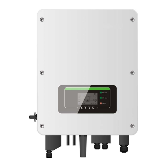
3. Installation 3.1. Product Overview HYD‐ES inverter is 100% strictly inspected before package and delivery. It is forbidden to put the HYD‐ES inverter upside down during delivery. CAUTION Please check the product package and fittings carefully before installation. Fig. 2 HYD‐ES inverter overview 1 DC switch 6 Current transformer port 2 Battery input terminals 7 Load connection port 3 PV input terminals Grid connection port ... -
Page 8: Packing List
3.2. Packing List Inspect the package and fittings carefully before installation. You should have the following fittings: Mounting Bracket × 1 AC terminal × 6 M5 screw × 2 Battery terminal × 2 M6 flat washer × 8 CT terminal × 2 Terminal cap × 4 Expansion Bolts × 8 User Manual × 1 Warranty card × 1 Quality Certificate × 1 Current Transformer × 1 NTC×1 (Long‐3M) PV+ input terminal×2 PV‐ input terminal×2 Communication cable × 1 Fig. 3 Accessories of HYD‐ES inverter 3.3. Installation Environment Choose a dry, clean, and tidy place, convenient for installation ... -
Page 9: Installation Tools
3.4. Installation Tools The following tools shall be prepared before installation: No. Tool Model Function Hammer drill 1 Used to drill holes on the wall Recommend drill dia.6mm 2 Screwdriver wiring 3 Wire stripper Strip wire Turn the screw to connect rear panel 4 4mm Allen Key with inverter 5 Crimping tools Used to crimp power cables 6 Multi‐meter Used to check grounding 7 Marker pen Used to mark signs 8 Measuring tape Used to measure distances ... -
Page 10: Installation Position
11 Safety goggles Operators wear 12 Anti‐dust respirator Operators wear 3.5. Installation Position HYD‐ES inverter should be vertically mounted (to ensure fast heat dissipation), please choose a position without direct sunlight / snow accumulation to install HYD‐ES inverter. Please the installation position is well‐ventilated. Fig. 4 Installation Position of HYD‐ES inverter 10 / 43 ... -
Page 11: Mount Hyd-Es Inverter
3.6. Mount HYD‐ES inverter Step 1: Put the mounting bracket properly on the wall, mark these 8 drill holes using a marker pen. Drill 8 holes (drill bit 6mm) on the wall. Step 2: Insert the expansion screw vertically into the hole, note the insertion depth. (not too shallow or too deep) Step 3: Fix the mounting bracket on the wall using bolts & flat washers. Step 4: Put HYD‐ES inverter on the mounting bracket. Step 5: Earth HYD‐ES inverter using the grounding hole on the heat sink. Step 6: OPTIONAL: you can lock HYD‐ES inverter to the mounting bracket. Step 5 Step 6 11 / 43 ... -
Page 12: Electrical Connection
4. Electrical Connection CAUTION High voltages in power conversion circuits. Lethal hazard of electric shock or serious burns. All work on the PV modules, inverters, and battery systems must be carried out by qualified personnel only. Wear rubber gloves and protective clothing (protective glasses and boots) when working on high voltage/high current systems such as INVERTER and battery systems. CAUTION HYD‐ES inverter is intended to be used in PV system with battery storage. If not used as intended, the protection provided by the equipment may be impaired. Fig. 5 Electrical connections 12 / 43 ... -
Page 13: Battery Connection
4.1. Battery Connection Fig. 6 Battery connection (Measure battery wires polarity/voltage before connection) Step 1: Loosen 4 screws (A) using a screwdriver (Fig. 6); Step 2: Remove the waterproof cover (B), loosen the cable gland (C), and then remove the stopper (G); Step 3: Route the battery wires (F) through the cable gland, then connect battery wires using OT terminal (E); tep 4: Fasten the waterproof cover using 4 screws. 4.2. PV Connection Recommended DC input cable specifications Cross‐Sectional Area (mm External Cable Diameter(mm ) Range Recommended Value 4.0~6.0 4.5~7.8 Procedure : Step 1 Prepare PV positive and negative power cables 1. Positive metal contact 2. Negative metal contact Fig. 7 prepare PV positive and negative power cables 13 / 43 ... - Page 14 Step 2 Insert crimped PV positive and negative power cables into corresponding PV connectors 3. Positive connector 4. Negative connector Fig. 8 prepare PV positive and negative connectors Step 3 Make sure the DC voltage of each PV string is less than 600V DC and polarities of PV power cables are correct. Insert the positive and negative connectors into HYD‐ES inverter until you hear a "click" sound, as shown in Fig. 9. 1. Bayonet Fig. 9 Connect PV connectors CAUTION Before removing the PV positive and negative connectors, ensure that the DC SWITCH is OFF. Follow-up Procedure Use a MC4 wrench to disconnect PV connectors, as shown in Fig. 10. Fig. 10 Disconnect PV connectors 14 / 43 ...
-
Page 15: Ct / Can / Rs485 / Ntc Connection
4.3. CT / CAN / RS485 / NTC connection CT (Current transformer) can measure the value and direction of AC current. Refer to Fig. 11 for the correct connection of CTa. Fig. 11 CTa connection Step 1: Refer to Fig. 11 for correct position of CTa. Wrap the CT around L wire of incoming mains, make sure that the CT arrow direction is “home → grid”. Step 2: You can use network cable & terminal caps to extend CT wires if necessary, the maximum CT cable length is 200m. CT wire Extension cable (network cable) HYD‐ES inverter Red Orange / white orange / brown / white brown CT+ Black Green / white green / blue / white blue CT‐ 15 / 43 ... - Page 16 Fig. 12 CT / CAN / RS485 / NTC connection Step 3: Loosen 4 screws (part A) using a screwdriver (Fig. 12) Step 4: Remove the waterproof cover (part B), loosen the cable gland (part C), then remove the stopper (part G) Step 5: Route CT cable through the cable gland, connect CT cable to CT terminal, then insert CT terminal into corresponding ports. Step 6: One communication cable (between battery BMS & HYD‐ES inverter) is provided in the HYD‐ES inverter accessory bag. One inverter end, one BAT end. ...
-
Page 17: Grid Connection
Fig. 13 NTC connection Step 8: fasten the waterproof cover using 4 screws. 4.4. Grid Connection Step 1: Loosen 4 screws (part A) using a screwdriver (fig. 14) Step 2: Remove the waterproof cover (part B), loosen the cable gland (part C), then remove the stopper (part G) Step 3: Route a 3‐core cable through GRID cable gland, then connect 3 wires to corresponding terminal blocks. (BROWN – L, BLUE – N, YELLOW/GREEN – PE) Step 4: Fasten the waterproof cover using 4 screws. Fig. 14 Grid & Load connection 17 / 43 ... -
Page 18: Critical Load Connection (Eps Function)
4.5. Critical Load Connection (EPS function) Critical load: in case of grid outage, if EPS function is enabled, HYD‐ES inverter will work in EPS (Emergency Power Supply) mode, utilize the PV power & energy stored in the battery to supply power to critical load via LOAD connection port. LOAD connection port is only for critical load connection. The power of critical loads must be less than 3000VA. The connection procedure of LOAD port is the same as grid connection (Fig. 14). Change-over positions CAUTION The changeover switch is necessary. While checking/repairing critical load, make sure change‐over switch is at position 0. While checking/repairing HYD‐ES inverter, make sure change‐over switch is at position 0 & HYD‐ES inverter is disconnected from grid. Under normal conditions: change‐over switch is at position 1. HYD‐ES inverter can supply power to critical load in case of blackout. If the HYD‐ES inverter is faulty, manually change the switch to position 2. Grid will supply power to critical load. Fig. 15 Change‐over Switch connections 18 / 43 ... -
Page 19: Buttons And Indicator Lights
5. Buttons and indicator lights Fig 16. Buttons and indicator lights 5.1. Buttons: press “Back” to the previous screen or enter the main interface; press “Up” to the upper menu option or value plus 1; press “Down” to the lower menu option or value minus 1; Press “OK” to select the current menu option or switch to the next digit. 5.2. Indicator lights and status of HYD‐ES inverter On Grid Off‐Grid Alarm Status of HYD inverter Green light Green light Red light On‐grid Standby (On‐Grid) Flashing Off‐Grid ON Standby (Off‐Grid) Flashing ... -
Page 20: Operation
6. Operation 6.1. Double Check Please double check the following before operation. HYD‐ES inverter is firmly fastened to the mounting bracket on the wall; PV+/PV‐ wires are firmly connected, polarity and voltage are correct; BAT+/BAT‐ wires are firmly connected, polarity and voltage are correct; DC isolator is correctly connected between battery & HYD‐ES inverter, DC isolator: OFF; GRID / LOAD cables are firmly / correctly connected; AC circuit breaker is correctly connected between HYD‐ES inverter GRID port & GRID, circuit breaker: OFF; AC circuit breaker is correctly connected between HYD‐ES inverter LOAD port & critical load, circuit breaker: OFF; For lithium battery, please ensure that the communication cable has been correctly connected; For the lead‐acid battery, please ensure that the NTC wire has been correctly connected. 6.2. First Time Setup (IMPORTANT!) IMPORTANT: PLEASE FOLLOW THE FOLLOWING PROCEDURE to switch ON HYD‐ES inverter Make sure there’s no power generation in HYD‐ES inverter’s phase. Turn ON DC switch. Switch ON the battery. Turn ON DC isolator between battery & HYD‐ES inverter. Turn ON AC circuit breaker between the HYD‐ES inverter GRID port & GRID. Turn ON AC circuit breaker between the HYD‐ES inverter LOAD port & critical load. HYD‐ES inverter should start to operate now. You need to set the following parameters before HYD‐ES inverter starts to operate. 1)Set system time 8)*Set min discharge voltage 2)Set country 9)*Set max discharge current 3)Select battery type 10)*Set min protect voltage 4)*Set battery capacity 11)*Set discharge depth 5)*Set max charge voltage 12)*Set empty discharge voltage 6)*Set max charge current 13)*Set full charge voltage 7)*Set max protect voltage ... - Page 21 1)Set system time System time format is “20YY‐MM‐DD‐HH‐MM‐SS”, press “Up” or “Down” to change the 1 digit, press “OK” to switch to next digit, press “Ok” to complete setting. When system time setting is complete, “Set country” will pop up. 2)Set country Press “Up” or “Down” to select a country, press “Ok” to complete the country setting. When country setting is complete, “Set battery type” will pop up. Code Country Code Country Code Country 00 Germany VDE4105 11 France Europe General 01 CEI‐021 Internal ...
- Page 22 Note: Please confirm with representative of PYLONTECH that your battery is compatible with HYD3000/4000/5000/6000‐ES 2. DARFON DARFON 14S31P ESS 3.DEFAULT LEAD ACID / LEAD CRYSTAL / AQUION battery 4. General Lithium All batteries that comply with SOFAR’S BMS CAN communication protocol. 5. Alpha. ESS M48112‐P / SMILE‐BAT 6. SOLTARO SL‐3KWH / SL‐1KWH 4)*Set battery capacity (only for DEFAULT battery type) Press “Up” or “Down” to change the 1 digit, press “OK” to switch to next digit. After changing the battery capacity per your battery specification, press “Ok”, then “Set max charge voltage” will pop up. 5)*Set max charge voltage (only for DEFAULT battery type) Press “Up” or “Down” to change the 1 digit, press “OK” to switch to next digit. After changing max charge voltage per your battery specification, press “Ok”, then “Set max charge current” will pop up. 6)*Set max charge current (only for DEFAULT battery type) Press “Up” or “Down” to change the 1 digit, press “OK” to switch to next digit. After changing the max charge current per your battery specification, press “Ok”, then “Set max protect voltage” will pop up. 7)*Set max protect voltage (only for DEFAULT battery type) Press “Up” or “Down” to change the 1 digit, press “OK” to switch to next digit. After changing the max protect voltage per your battery specification, press “Ok”, then “Set min discharge voltage” will pop up. 8)*Set min discharge voltage (only for DEFAULT battery type) Press “Up” or “Down” to change the 1 digit, press “OK” to switch to next digit. After changing the min discharge voltage per your battery specification, press “Ok”, then “Set max discharge current” will pop up. 9)*Set max discharge current (only for DEFAULT battery type) Press “Up” or “Down” to change the 1 digit, press “OK” to switch to next digit. After changing the max discharge current per your battery specification, press “Ok”, then “Set min protect voltage” will pop up. 10)*Set min protect voltage (only for DEFAULT battery type) Press “Up” or “Down” to change the 1 digit, press “OK” to switch to next digit. After changing the min protect voltage ...
-
Page 23: Commissioning
Press “Up” or “Down” to change the 1 digit, press “OK” to switch to next digit. After changing the empty discharge voltage per your battery specification, press “Ok”, then “Set full charge voltage” will pop up. 13)*Set full charge voltage (only for DEFAULT battery type) Press “Up” or “Down” to change the 1 digit, press “OK” to switch to next digit. After changing the full charge voltage per your battery specification, press “Ok”. Congratulations, HYD3000/4000/5000/6000‐ES’s first‐time setup is complete. Please press “OK” to enter the main interface. 6.3. Commissioning The main interface: Fig 17. Main interface If you didn’t change the work mode of HYD‐ES inverter, which means HYD‐ES inverter is working in “Auto Mode”: While “PV Production” > “Home Consumption” If the battery is not full. HYD‐ES inverter will charge the battery. While “PV Production” < “Home Consumption” If the battery is not flat. HYD‐ES inverter will discharge the battery. 6.4. Menu In the main interface, press “Down” button to enter grid/battery parameters page: Main Interface Press “Down” 1.Grid(V) 2.AC Current(A) 3.Frequency 23 / 43 ... -
Page 24: Basic Setting
4.Batt(V) 5.Batt Chrg Curr. 6.Batt DisChrg Curr. 7.State of Charge 8.Batt Cycles 9.Batt Temp. In the main interface, press “UP” button to enter PV parameters page: Main Interface Press “UP” 1.PV1 Voltage 2.PV1 Current 3.PV1 Power 4.PV2 Voltage 5.PV2 Current 6.PV2 Power 7.Inverter Temp. In the main interface, press “back” button to enter main menu. The main menu has the following five options: Main Interface Press “Back” 1.Basic Setting 2.Advanced Setting “Up” ↑ 3.Event List 4.System Information “Down”↓ 5.Energy Statistic 6.Software Update 6.4.1. Basic setting 1.Basic Setting Press “OK”... - Page 25 5.EPS Mode 6.Communication Addr. “Down”↓ 7.Auto Test 1. Set Language Select “1. Language”, press “OK”. Press “up” or “down” to select the language and press “OK”. Easier Way: press “Back” & “OK” at the same time to change system language. 2. Set Time Select “2. Time”, press “OK” to enter time setting interface, system time format is 20YY‐MM‐DD HH:MM:SS Press “Up” or “Down” to change the 1 digit, press “OK” to switch to next digit, after inputting the current time, press “OK”. 3. Energy Storage Mode Select “3. Energy Storage Mode”, press “OK” to enter energy storage mode setting interface. 3.Energy Storage mode 1. Self‐use Mode “Up” ↑ 2. Time‐of‐use Mode 3.Timing Mode “Down”↓ 4. Passive Mode 1) Set Auto Mode Select “1. Set Auto Mode”, then press “OK”. In auto mode, HYD‐ES inverter will automatically charge & discharge the battery. If PV generation = LOAD consumption ( Δ...
- Page 26 If the battery is full(or already at Max Charge Power), If PV generation < LOAD consumption, it will excess power will be exported to the grid. discharge the battery to supply power to load. If PV generation + Battery < LOAD consumption, HYD‐ Press “DOWN” button to view current grid/battery ES inverter will import power from the grid. parameters, press “UP” to get back to main interface. 2) Set Time‐of‐use Mode Select “2. Set Time‐of‐use Mode”, and then press “OK” to enter Set Time‐of‐use mode interface. Set Time‐of‐use Mode Rules. 0: Enabled From To SOC Charge 02h00m ‐ 04h00m 070% 1000W Effective date Dec. 22 ‐ Mar. 21 Weekday select Mon. Tue. Wed. Thu. Fri. Sat. Sun. If electricity is more expensive in high demand time (peak rate) & electricity is much cheaper in low demand time (off‐...
- Page 27 You can select an off‐peak period to charge your battery. Outside the off‐peak charge period, HYD‐ES inverter is working in Auto Mode. If your family normally go to work/school on weekdays & stay at home on weekends, which means the home electricity consumption is much higher on weekends. Thus, you need to store some cheap electricity on weekends only. This is possible using our Time‐of‐use mode. In summer, if your PV system can produce more electricity than your home electricity consumption. Then you don’t need to set an off‐peak charge period to charge your battery in summer at all. You can select an effective date (normally winter) for Time‐of‐use mode in this case. Outside the effective date, HYD‐ES inverter is working in Auto ...
- Page 28 If PV generation > LOAD consumption ( Δ P > 100W), If PV generation = LOAD consumption, HYD‐ES inverter wont’ charge or discharge battery. HYD‐ES inverter will charge battery. 4) If PV generation is normal,but LOAD consumption=0, If PV generation < LOAD consumption ( Δ P > 100W), the surplus power will be stored in the battery. HYD‐ES inverter will discharge battery. 6. Communication Addr. Select “6. Set Communication Addr.”, press “OK”. Press “Up” or “Down” to change the 1 digit, press “OK” to switch to next digit, after changing the 485‐communication address (default :01), press “OK”. 7. Auto Test (ONLY for Italian Market) Select “7. Auto Test”, press “OK” to enter autotest interface. 7.Auto Test 1.Autotest Fast 2.Autotest STD “Up” ↑ 3.QF Time Setting 4.QV Time Setting “Down”↓ 5.Control 81.S1 28 / 43 ...
- Page 29 1) Autotest Fast Select “1. Autotest Fast”, then press “OK” to start Auto test Fast. Start Autotest ↓ Press “Ok” to start Testing 59.S1... ↓ Wait Test 59.S1 OK! ↓ Wait Testing 59.S2... ↓ Wait Test 59.S2 OK! ↓ Wait Testing 27.S1... ↓ Wait Test 27.S1 OK! ↓ Wait Testing 27.S2... ↓ Wait Test 27.S2 OK! ↓ Wait Testing 81>S1... ↓ Wait Test 81>S1 OK! ↓ Wait Testing 81>S2… ↓ Wait Test 81>S2 OK! ...
- Page 30 27.S1 threshold 195.5V 400ms ↓ Press “Down” 27.S1: 228V 408ms ↓ Press “Down” 27.S2 threshold 92V 200ms ↓ Press “Down” 27.S2: 227V 205ms ↓ Press “Down” 81>.S1 threshold 50.5Hz 100ms ↓ Press “Down” 81>.S1 49.9Hz 103ms ↓ Press “Down” 81>.S2 threshold 51.5Hz 100ms ↓ Press “Down” 81>.S2 49.9Hz 107ms ↓ Press “Down” 81<.S1 threshold 49.5Hz 100ms ↓ Press “Down” 81<.S1 50.0Hz 105ms ↓ Press “Down” 81<.S2 threshold 47.5Hz 100ms ↓ Press “Down” 81<.S2 50.1Hz 107ms 2) Autotest STD Select “2. Autotest STD”, then press “OK” to start Auto test STD. The test procedure is same as Autotest Fast, but it’s much more time consuming. ...
-
Page 31: Advanced Setting
6.4.2. Advanced setting 2.Advanced Setting Input Password 0001 1.Battery Parameter 2.Clear Energy Data 3.Clear Events Up” ↑ 4.Country 5.Anti Reflux “Down”↓ 6.IV Curve Scan 7.Battery Active 8.DRMs0 Control 9.Safety Param. Select “2. Advanced Setting” and press “OK”, “input password” is shown. Input the password ”0001”, press “Up” or “Down” to change the 1 digit, press “OK” to switch to next digit, when “0001” is shown on the screen, press “OK” to enter “2. Advanced Setting” interface. If “Incorrect, Try Again!” is shown on the screen, press “Back” and input the password again. 1. Battery Parameter 1.Battery Parameter 1)Battery Type 7)Max Discharge (A) 2)*Battery Capacity 8)*Low (V) Protection “Up” ↑ 3)Discharge Depth 9)*Min Discharge (V) 4)Max Charge (A) 10)*Empty Discharged (V) “Down”↓ ... - Page 32 EPS Discharge Depth per battery specification. Press “OK”. For example: if Discharge Depth = 50% & EPS Discharge Depth = 80%. While grid is connected: HYD‐ES inverter won’t discharge the battery when its SOC is less than 50%. In case of blackout: HYD‐ES inverter will work in EPS mode (if EPS mode is enabled) & keep discharging the battery till battery SOC is less than 20%. 4) Max. Charge (A) Select “4. Max. Charge (A)” and press “OK”. Press “up” or “down” to change the 1 digit, press “ok” to switch to next digit. Input the value of Max. Charge (A) per battery specification. Press “OK”. 5) *Over (V) Protection (only for DEFAULT battery type) Select “5. Over (V) Protection” and press “OK. Press “up” or “down” to change the 1 digit, press “ok” to switch to next digit. Input the value of Over (V) Protection per battery specification. Press “OK”. 6) *Max. Charge (V) (only for DEFAULT battery type) Select “6. Max. Charge (V)” and press “OK”. Press “up” or “down” to change the 1st digit, press “ok” to switch to next digit. Input the value of Max. Charge (V) per battery specification. Press “OK”. 7) Max. Discharge (A) Select “7. Max. Discharge (A)” and press “OK”. Press “up” or “down” to change the 1 digit, press “ok” to switch to next digit. Input the value of Max. Discharge (A) per battery specification. Press “OK”. 8) *Low (V) Protection (only for DEFAULT battery type) Select “8. Low (V) Protection” and press “OK”. Press “up” or “down” to change the 1 digit, press “ok” to switch to next digit. Input the value of Low (V) Protection per battery specification. Press “OK”. 9) *Min. Discharge (V) (only for DEFAULT battery type) Select “9. Min. Discharge (V)” and press “OK”. Press “up” or “down” to change the 1 digit, press “ok” to switch to next digit. Input the value of Min. Discharge (V) per battery specification. Press “OK”. 10) * Empty Discharged (V) (only for DEFAULT battery type) Select “10. Empty Discharged (V)” and press “OK”. Press “up” or “down” to change the 1 digit, press “ok” to switch to next digit. Input the value of Empty Discharged Voltage per battery specification. Press “OK”. 11) * Full Charged (V) (only for DEFAULT battery type) ...
- Page 33 Select “4. Country”, press “OK”, current country setting is shown, input new country code & press “OK” 5. Anti Reflux 5.Anti Reflux Control 1.Anti Reflux Control Enable “Up” ↑ Disable 2.Reflux Power “Down”↓ ***KW The user can enable “Anti Reflux Control” to limit the max export power to grid. Select “2. Reflux Power” to input desired max export power to grid. 6. IV Curve Scan 6.IV Curve Scan 1.Scan Control Enable “Up” ↑ Disable 2.Scan Period ***min “Down”↓ 3.Force Scan The user can enable “IV Curve Scan” (MPPT scan) to make HYD‐ES inverter to find the global max power point periodically to deliver max power from a partially shaded PV array. ...
-
Page 34: Event List
Select “9. Safety Param.”, press “OK”, press “up” or “down” to select “1. Set START Parameters”, “2. Set Safety Voltage”, “3. Set Safety Frequency” or “4.Set Insulation”, then press “OK”. Please contact SOFAR technical support for more information. 6.4.3. Event List 3.Event List 1.Current Event List “Up” ↑ 2.History Event List “D ”↓ Event list of HYD‐ES inverter, including current event list and history event list. 1) Current Event List Select “1. Current Event List”, press “OK” to check the current events. 2) History Event List Select “2. History Event List”, press “OK” to check the historical events. Press “up” or “down” to check all historical events if there’re more than 1 page of events. 6.4.4. System information interface 4.System Information 1.Inverter Info Inverter Info (1) Product SN Software Version Hardware Version Power Level Inverter Info(2) Country ... -
Page 35: Energy Statistic
3.Safety Param. Safety Param.(0) OVP 1 OVP 2 UVP 1 UVP 2 Safety Param.(1) OFP 1 OFP 2 UFP 1 UFP 2 Safety Param.(2) OVP 10mins 6.4.5. Energy Statistic 5.Energy Statistic Today PV ***KWH Load ***KWH Export ... -
Page 36: Software Upgrade
Discharge ***KWH Charge ***KWH Discharge ***KWH Select “5. Energy Statistic”, press “OK” to enter Energy Statistic interface, it shows the energy generation and consumption within a certain range of time. Press “Up” or “Down” to check the daily / weekly / monthly / yearly / lifetime energy statistics. 6.4.6. Software upgrade Copy the firmware folder to the root directory of SD card. Select “6. Software Update”, press “OK”, “input password” is shown. Input the password (”0715”), press “Up” or “Down” to change the 1 digit, press “OK” to switch to next digit, when “0715” is shown on the screen, press “OK”. ... -
Page 37: Technical Data
7. Technical Data Model HYD 3000-ES HYD 3600-ES HYD 4000-ES HYD 5000-ES HYD 6000-ES Battery Parameters Battery Type Lead‐acid, Lithium‐ion Nominal battery voltage 48V Battery voltage range 42 ‐ 58V Lithium:(according to BMS), General 46.0V Min discharge voltage Lead acid: 44.0V Lithium‐ion:(according to BMS), Max 58V Max charge voltage Lead acid: 58V Recommended battery capacity 200Ah (100 – 500 Ah optional) Recommended storage capacity 9.6 kWh Max charge current Charge current range 0 – 65A programmable Charge curve 3 ‐ stage adaptive with maintenance Max discharge current 0 – 70A programmable Battery protection Over voltage protection / Over current protection / Over temperature protection Depth of discharge Lithium: 0 – 80% DOD adjustable Lead acid: 0 – 50% DOD adjustable PV parameters ... - Page 38 Max output power 3000W 3680W 4000W 5000W 6000W Max output current 13.7A 16A 18.2A 22.8A 27.3A Output current protection(Ipeak) 29.2A 33.6A 33.6A 47.1A 54.5A Nominal grid voltage & frequency 220V,230V,240V, 44 – 55Hz or 54 – 66Hz AC voltage range 180 – 276V (according to local authority requirements) THD <3% Power factor 1default (+ / ‐ 0.8 adjustable) Inrush current 0.8A / 1us Max output fault current 100A / 1us System parameters Max efficiency Charge: 94.1% / discharge 94.3% Standby losses < 5W (PV SPS) Topology High frequency isolation(for bat) ...
-
Page 39: Troubleshooting
8. Troubleshooting Code Name Description Solution If the alarm occurs occasionally, the possible cause is that the electric grid is abnormal occasionally. ID01 GridOVP The grid voltage is too high HYD‐ES inverter will automatically return to normal operating status when the electric grid’s back to normal. If the alarm occurs frequently, check whether the grid voltage/frequency is within the acceptable ID02 ... - Page 40 The battery current is too ID12 HwBatOCP high and has triggered hardware protection If the fault occurs occasionally, the possible cause is that the external circuits are abnormal occasionally. HYD‐ES inverter automatically returns to normal The GFCI sampling value operating status after the fault is rectified. ID13 GFCI OCP between the master DSP and If the fault occurs frequently and lasts a long time, slave DSP is not consistent check whether the insulation resistance between the PV array and earth(ground) is too low, also check the insulation conditions of PV cables. ...
- Page 41 high Check whether the input current is higher than the maximum input current of HYD‐ES inverter, then ID32 SwBOCPInstant The input current is too high check the input wiring, if both are correct, please contact technical support. Check the PV input mode (parallel mode/ ID33 PvConfigSetWrong Incorrect input mode independent mode) setting of HYD‐ES inverter. If it’s incorrect, change the PV input mode. The GFCI sampling value ID48 ConsistenFault‐fault between the master DSP and slave DSP is not consistent The grid voltage sampling value ...
- Page 42 Please make sure HYD‐ES inverter is installed in a OverTempFault_ The temperature of heat sink cool / well‐ventilated place. ID58 is too high HeatSink Make sure the inverter is vertically installed & the ambient temperature is less than the temperature The environment temp is too ID59 OverTempFault_Env upper limit of HYD‐ES inverter high ID60 PE connectFault Check the grounding of AC output PE wire. The grid current is too high ID65 unrecoverHwAcOCP and has cause unrecoverable hardware fault ID65‐ID67 are internal faults of HYD‐ES inverter, switch ...
- Page 43 Long dist Load HYD‐ES inverter receives a remote signal to ID83 Remote power derate Shedding decrease its power. Switch OFF HYD series HYD‐ES inverter receives a remote signal to switch ID84 Long dist OFF inverter remotely OFF. For example, if you set DOD to 30%, when SOC is less than 70%, you will see ID85 in the event list. SOC <= 1 ‐DOD HYD‐ES inverter won’t discharge the battery when ID85 is present. ID85 or ...
Need help?
Do you have a question about the HYD 3600-ES and is the answer not in the manual?
Questions and answers