
Related Manuals for Sofar solar 3K-6KTLM-G2


Summary of Contents for Sofar solar 3K-6KTLM-G2
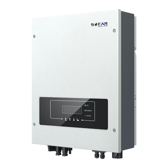
- Page 1 User manual Solar Grid-tied Inverter Product Model: SOFAR 3K-6KTLM-G2 S h e n z h e n S O FA R S O L A R C O . , L t d .
-
Page 2: Table Of Contents
Contents Preface............................II 1. Basic safety information....................- 1 - 1.1. Safety instructions....................- 1 - 1.2. Symbols and signs....................- 4 - 2. Product characteristics...................... - 6 - 2.1. Product dimensions..................... - 6 - 2.2. Function description....................- 8 - 2.3. Efficiency curve....................- 10 - 3. - Page 3 User manual SOFAR 3K~6KTLM-G2 Notice This manual contains important safety instructions that must be followed during installation and maintenance of the equipment. Save these instructions! This manual must be considered as an integral part of the equipment. The manual must always accompany the equipment, even when it is transferred to another user or field.
-
Page 4: Preface
User manual SOFAR 3K~6KTLM-G2 Preface Outline Please read the product manual carefully before installation, operation or maintenance. This manual contains important safety instructions and installation instructions that must be followed during installation and maintenance of the equipment. Scope This product manual describes the installation, electrical connections, commissioning, maintenance and troubleshooting of SOFAR 3K~6KTLM-G2 inverters: SOFAR 3KTLM-G2... - Page 5 User manual SOFAR 3K~6KTLM-G2 Danger indicates a hazardous situation which, if not avoided, will result in death or serious injury. Danger Warning indicates a hazardous situation which, if not avoided, could result in death or serious injury. Warning Caution indicates a hazardous situation which, if not avoided, could result in minor or moderate injury.
-
Page 6: Basic Safety Information
User manual SOFAR 3K~6KTLM-G2 1. Basic safety information If you have any question or problem when you read the following information, please contact Shenzhen SOFARSOLAR Co., Ltd. Note Outlines of this chapter Safety instruction It mainly introduce the safety instruction when install and operate the equipment. - Page 7 User manual SOFAR 3K~6KTLM-G2 The customer must make sure the operator has the necessary skill and training to do his/her job. Staff in charge of using and maintaining the equipment must be skilled, aware and mature for the described tasks and must have the reliability to correctly interpret what is described in the manual.
- Page 8 User manual SOFAR 3K~6KTLM-G2 suitable ways and means for protecting the components (in particular, the electronic components) from violent shocks, humidity, vibration, etc. Electric connection Please comply with all the current electrical regulations about accident prevention in dealing with the solar invert. Before the electrical connection, make sure to use opaque material to cover the PV modules or to disconnect PV array DC switch.
-
Page 9: Symbols And Signs
User manual SOFAR 3K~6KTLM-G2 for 5 minutes at least before carrying out any maintenance or repair Danger work. Inverter should work again after removing any faults. If you need any repair work, please contact with the local authorized service center. Can’t open the internal components of inverter without authorized. - Page 10 User manual SOFAR 3K~6KTLM-G2 read and understand the content of the symbols, and then start the installation. There is a residual voltage in the inverter! Before opening the equipment, operator should wait for five minutes to ensure the capacitor is discharged completely. Caution, risk of electric shock.
-
Page 11: Product Characteristics
User manual SOFAR 3K~6KTLM-G2 2. Product characteristics Outlines of this chapter Product dimensions It introduces the field of use, and the overall dimensions of SOFAR 3K~6KTLM-G2 inverters. Function description It introduces how SOFAR 3K~6KTLM-G2 inverters work and the function modules inside. Efficiency curves It introduces the efficiency curves of in the inverter. - Page 12 User manual SOFAR 3K~6KTLM-G2 technical specifications. Only the photovoltaic modules can be connected to the input of the inverter (do not connect batteries or other sources of power supply). The choice of optional parts of inverter should be made by a qualified technician who knows the installation conditions clearly.
-
Page 13: Function Description
User manual SOFAR 3K~6KTLM-G2 Figure 2-4 Bracket dimensions of SOFAR3K~6KTLM-G2 Labels on the equipment The labels must NOT be hidden with objects and extraneous parts (rags, boxes, equipment, etc.); they must be cleaned regularly and kept visible at all times. 2.2. - Page 14 User manual SOFAR 3K~6KTLM-G2 same time, Control Board can trigger the relay so as to protect the internal components. Function module A. Energy management unit This control can be used to switch the inverter on/off through an external (remote) control. B.
-
Page 15: Efficiency Curve
User manual SOFAR 3K~6KTLM-G2 Electrical block diagram Figure2-5 Electrical block diagram 2.3. Efficiency curve - 10 - Copyright © Shenzhen SOFARSOLAR Co., Ltd... -
Page 16: Installation
User manual SOFAR 3K~6KTLM-G2 3. Installation Outlines of this chapter This topic describes how to install the SOFAR 3K~6KTLM-G2. Installation notes 3K~6KTLM-G2 Do NOT install the SOFAR on flammable material. 3K~6KTLM-G2 Do NOT install the SOFAR in an area used to store Flammable or explosive material. - Page 17 User manual SOFAR 3K~6KTLM-G2 Therefore, check the outer packing materials before installing the inverter. Check the outer packing materials for damage, such as holes and cracks. If any damage is found, do not unpack the SOFAR 3K~6KTLM-G2 and contact the dealer as soon as possible.
- Page 18 User manual SOFAR 3K~6KTLM-G2 M5Hexagon screws 3pcs Expansion bolts 7pcs M6 flat washer 8pcs Self-tapping screw 5pcs Manual 1pcs The warranty card 1pcs Outgoing inspection report 1pcs Registration Form 1pcs AC output terminal 1pcs 485 terminal (2pin) 1pcs M4X14 Cross round head triple set screw(Only for DC 1pcs switch lock)...
-
Page 19: Product Overview
User manual SOFAR 3K~6KTLM-G2 3.3. Product Overview SOFAR 3K~6KTLM-G2 inverter is 100% strictly inspected before package and delivery. It is forbidden to put the SOFAR 3K~6KTLM-G2 inverter upside down during delivery. Please check the product package and fittings carefully before installation. - Page 20 User manual SOFAR 3K~6KTLM-G2 Tool Model Function Hammer drill Recommend drill Used to drill holes on the wall. dia. 6mm Screwdriver wiring Removal tool Remove PV terminal Wire stripper Strip wire Turn the screw to connect rear 4mm Allen Wrench panel with inverter.
-
Page 21: Determining The Installation Position
User manual SOFAR 3K~6KTLM-G2 Safety goggles Operators wear Anti-dust respirator Operators wear 3.5. Determining the Installation Position Determine an appropriate position for installing the SOFAR 3K~6KTLM-G2 inverter. Comply with the following requirements when determining the installation position: Figure3-3 Installation Requirements - 16 - Copyright ©... -
Page 22: Moving The Sofar 3K~6Ktlm-G2
User manual SOFAR 3K~6KTLM-G2 clearance for single SOFAR 3K~6KTLM-G2 Inverter Installation of multiple SOFAR 3K~6KTLM-G2 inverter 3.6. Moving the SOFAR 3K~6KTLM-G2 This topic describes how to move the to the installation position Horizontally SOFAR 3K~6KTLM-G2. Step 1 Open the packaging, insert hands into the slots on both sides of the inverter and hold the handles, as shown in Figure 3-4 and Figure 3-5. -
Page 23: Installing Sofar 3K~6Ktlm-G2
User manual SOFAR 3K~6KTLM-G2 Figure 3-5 Moving the inverter (2) Step 2 Lift the SOFAR 3K~6KTLM-G2 from the packing case and move it to the installation position. To prevent device damage and personal injury, keep balance when moving the inverter because the inverter is heavy. Do not put the inverter with its wiring terminals contacting the floor because the power ports and signal ports are not designed to support the weight of the inverter. - Page 24 User manual SOFAR 3K~6KTLM-G2 Step 4 Hook the inverter to the rear panel. Using an M5 screw to secure the inverter to the rear panel to ensure safety.(Torque:25kgf.cm) Step 5 You can secure the inverter to the rear panel and protect if from stealing by installing an anti-theft lock (this action is optional).
-
Page 25: Electrical Connections
User manual SOFAR 3K~6KTLM-G2 4. Electrical Connections Outlines of this chapter This topic describes the SOFAR 3K~6KTLM-G2 inverter electrical connections. Read this part carefully before connecting cables. NOTE: Before performing electrical connections, ensure that the DC switch is OFF. Since the stored electrical charge remains in a capacitor after the DC switch is turned OFF. So it’s necessary to wait for at least 5 minutes for the capacitor to be electrically discharged. -
Page 26: Electrical Connection
User manual SOFAR 3K~6KTLM-G2 two live part in the worst-case rated operating condition when used as intended. Interface PV input interface DVCC AC output interface DVCC SD card interface DVCA RS485 interface DVCA CT interface DVCA Logic interface DVCA WiFi/GPRS/Ethernet interface DVCA PV terminal and DC switch parameters PV terminal... -
Page 27: Connecting Pgnd Cables
User manual SOFAR 3K~6KTLM-G2 4.2. Connecting PGND Cables Connect the inverter to the grounding electrode using protection ground (PGND) cables for grounding purpose. The inverter is transformer-less, requires the positive pole and negative pole of the PV array are NOT grounded. Otherwise it will cause inverter failure. -
Page 28: Connecting Dc Input Power Cables
User manual SOFAR 3K~6KTLM-G2 Note 1: L3 is the length between the insulation layer of the ground cable and the crimped part.L4 is the distance between the crimped part and core wires protruding from the crimped part. Note 2: The cavity formed after crimping the conductor crimp strip shall wrap the core wires completely. - Page 29 User manual SOFAR 3K~6KTLM-G2 4-5. Figure 4-5 Connecting DC input power cables 1.Positive power cable 2. Negative power cable Note: L2 is 2 to 3 mm longer than L1. Step 3 Insert the positive and negative power cables into corresponding cable glands.
-
Page 30: Connecting Ac Output Power Cables
User manual SOFAR 3K~6KTLM-G2 Step 6 Reinstall cable glands on positive and negative connectors and rotate them against the insulation covers. Step 7 Insert the positive and negative connectors into corresponding DC input terminals of the inverter until you hear a "click" sound, as shown in Figure 4-7. - Page 31 User manual SOFAR 3K~6KTLM-G2 (PDF) or power grid using AC output power cables. It is not allowed for several inverters to use the same circuit breaker. It is not allowed to connect loads between inverter and circuit breaker. AC breaker used as disconnect device, and the disconnect device Caution shall remain readily operable.
- Page 32 User manual SOFAR 3K~6KTLM-G2 Inverter is equipped with two types of IP66 AC connector Type connector Ⅰ are randomly equipped with one), and the AC output cable Type connector Ⅱ needs to be wired by the customer. The appearance of is shown in AC connector figure 4-11.
- Page 33 User manual SOFAR 3K~6KTLM-G2 Step 1 Select appropriate cables Step2 Disassemble the AC connector according to Table 4-2, Remove the according to the figure shown below: insulation layer of the AC output cable insert the AC output cable (with its using a wire stripper according to the insulation layer stripped according to figure shown below:...
- Page 34 User manual SOFAR 3K~6KTLM-G2 sure that all the wires are securely rotate the AC connector clockwise until connected. the fastener reaches its designated Figure 4-15 position, as shown below. Figure 4-16 Removing the AC connector Pull out the AC connector by rotating the knob counterclockwise.
- Page 35 User manual SOFAR 3K~6KTLM-G2 Step 1 Select appropriate cables Step 2 Disassemble the AC according to Table 4-2, Remove the connector according to the figure insulation layer of the AC output cable shown below: insert the AC output using a wire stripper according to the cable (with its insulation layer figure shown below: A:15-25mm stripped according to step 1) through...
-
Page 36: Rs485, Ct, Logic Interface Connection
User manual SOFAR 3K~6KTLM-G2 Step 4 Insert the AC connector and Step 5 Connect the connected AC hear "click", then tighten the connector to the AC connector of the waterproof nut at the instantaneous inverter. Turn the ac connector knob value, as shown in the figure below, to to lock until you hear a "click"... - Page 37 User manual SOFAR 3K~6KTLM-G2 Table 4-5 Recommended communication cable size are shown below, The wiring methods are the same for RS485 and CT, this part describes their wiring methods and logic interface wiring method. Communication function RS485 Cable size 0.5~1.5mm² 0.5~1.5mm²...
- Page 38 User manual SOFAR 3K~6KTLM-G2 waterproof connector; Figure 4-26 A1:Waterproof stopper Step4 Select appropriate cable according Table4-4,remove the insulation layer using a wire stripper, the length of the wire core is about 6mm,insert the cable through the cable gland and waterproof cover, according to Table4-6,connect the wires as per the labels, and secure the wire using a slotted screwdriver.as shown in the figure below: Table 4-6 Function description of the communication terminals...
- Page 39 User manual SOFAR 3K~6KTLM-G2 1. About the use of CT Refer to the figure below and put the CT in the correct position. Figure 4-28 Enable counter-current protection and set counter-current power.Please refer to the operation steps in section 6.3(A)17. 2.
- Page 40 User manual SOFAR 3K~6KTLM-G2 requirements. Logic interface for AS/NZS 4777.2:2015, also known as inverter demand response modes (DRMs). The inverter will detect and initiate a response to all supported demand response commands within 2 s. The inverter will continue to respond while the mode remains asserted.
- Page 41 User manual SOFAR 3K~6KTLM-G2 Pin NO. Pin name Description Connected to (RRCR) Relay contact 1 input K1 - Relay 1 output Relay contact 2 input K2 - Relay 2 output Relay contact 3 input K3 - Relay 3 output Relay contact 4 input K4 - Relay 4 output Relays common node Not Connected...
-
Page 42: Wi-Fi/Gprs/Ethernet Module Installation Procedure
User manual SOFAR 3K~6KTLM-G2 Table 4-11 The inverter is preconfigured to the following RRCR power levels. Relay status: close is 1, open is 0 Active Power Power drop rate Cos(φ) <5 seconds 100% Step4 Insert the terminal as per the printed label, and then tighten the screws to fix the waterproof cover, rotate the cable gland clockwise to fasten it securely.(Torque:10-15kgf.cm)... -
Page 43: Communication Method
User manual SOFAR 3K~6KTLM-G2 4.7. Communication method SOFAR 3K~6KTLM-G2 gird-connected inverters offer RS485 (standard) and Wi-Fi communication modes (GPRS/Ethernet optional): A. Communication between one inverter and one PC: 1. RS485 Refer to the figure shown below, connect the TX+ and TX- of the inverter to the TX+ and TX- of the RS485→... - Page 44 User manual SOFAR 3K~6KTLM-G2 Wi-Fi/GPRS/Ethernet Refer to the figure shown below: (wireless function required for the PC). Figure 4-34 The operation information (generated energy, alert, operation status) of the inverter can be transferred to PC or uploaded to the server via Wi-Fi /GPRS/ Ethernet.
- Page 45 User manual SOFAR 3K~6KTLM-G2 RS485→USB adapter; connect the USB port of the adapter to the computer. A maximum of 31 inverters can be connected in one daisy chain. (NOTE2) Figure 4-35 2. WI-FI/GPRS/Ethernet Refer to the figure shown below: (wireless function required for the PC). Figure 4-36 The operation information (generated energy, alert, operation status) of the inverter can be transferred to PC or uploaded to the server via...
- Page 46 User manual SOFAR 3K~6KTLM-G2 Note3: S/N number of the Wi-Fi/GPRS/Ethernet module is located on the side. Note4: Specific use methods of Wi-Fi/GPRS/Ethernet can refer to the operation manual of Wi-Fi/GPRS/Ethernet. - 41 - Copyright © Shenzhen SOFARSOLAR Co., Ltd...
-
Page 47: Commissioning Of Inverter
User manual SOFAR 3K~6KTLM-G2 5. Commissioning of inverter 5.1. Safety inspection before commissioning Ensure that DC and AC voltages are within the acceptable range of the inverter. Attention 5.2. Start inverter Step 1: Turn ON the DC switch. (optional) Step 2: Turn ON the AC circuit breaker. When the DC power generated by the solar array is adequate, the SOFAR 3K~6KTLM-G2 inverter will start automatically. -
Page 48: Operation Interface
User manual SOFAR 3K~6KTLM-G2 6. Operation interface Outlines of this chapter This section introduces the display, operation, buttons and LED indicator lights of SOFAR 3K~6KTLM-G2 Inverter. 6.1. Operation and Display Panel Buttons and Indicator lights Key-button: · Back :to return to previous menu or enter into main menu from the standard interface. -
Page 49: Standard Interface
User manual SOFAR 3K~6KTLM-G2 OFF: ‘Normal’ state ·GFCI Warning Light (RED) ON: ‘ID12: GFCI Fault’ or ‘ID20: GFCI Device Fault’ OFF: GFCI normal 6.2. Standard Interface When power-on, LCD interface displays INITIALIZING, refer below picture. when control board successfully connected with communication board, the LCD display the current state of the inverter,display as shown in the figure below. - Page 50 User manual SOFAR 3K~6KTLM-G2 Inverter states includes: wait、check、normal、fault and permanent Wait: Inverter is waiting to Check State at the end of reconnection time. In this state, grid voltage value is between the max and min limits and so on; If not, Inverter will go to Fault State or Permanent State.
-
Page 51: Main Interface
User manual SOFAR 3K~6KTLM-G2 6.3. Main Interface Normal ------Press “back” 1.Enter Setting 2.Event List 3.SystemInfo 4.Display Time 5.Software Update (A) “Enter Setting” Interface as below: 1.Enter ------Press “back” Setting 1.Set time 12.Set Safety Voltage 2.Clear Energy 13.Set Safety Frequency 3.Clear Events 14.Set Insulation 4.Set Country 15.Set Reactive... - Page 52 User manual SOFAR 3K~6KTLM-G2 3. Clear Events Clean up the historical events recorded in the inverter. 4. Set Country Set up the safety regulation country that meets the current use conditions and requirements. Before setting this item, ensure that the“Enable Set Country” option are enabled .
- Page 53 Set the address (when you need to monitor multiple inverters simultaneously),Default 01. 9. Set Input mode SOFAR 3K-6KTLM-G2 has two MPPT channels, which can run independently or in parallel. Users choose the operation mode of MPPT according to the system design. Parallel mode is applicable to the case where...
- Page 54 User manual SOFAR 3K~6KTLM-G2 Enable or disable the power derate function of the inverter, and set the derate ratio. 17. Set Reflux Enable or disable the anti-reflux function of the inverter, and set the reflux power. This function needs to be used with external CT, please refer to this manual 4.5 RS485, CT, inverter logic interface connection for details.
- Page 55 User manual SOFAR 3K~6KTLM-G2 Set generation ratio. (B) “Event List” Interface as below: Event List is used to display the real-time event records, including the total number of events and each specific ID No. and happening time. User can enter Event List interface through main interface to check details of real-time event records, Event will be listed by the happening time, and recent events will be listed in the front.
-
Page 56: Update Software Online
Step 2 Insert the SD card into the compute. Step 3 SOFAR SOLAR will send the Software code to the user who needs to update. After user receive the file, please decompressing file and cover the original file in SD card. - Page 57 User manual SOFAR 3K~6KTLM-G2 state. User check current software version Systemlnfo>>3.SoftVersion. - 52 - Copyright © Shenzhen SOFARSOLAR Co., Ltd...
-
Page 58: Trouble Shooting
User manual SOFAR 3K~6KTLM-G2 7. Trouble shooting Outlines of this chapter This topic describes how to perform daily maintenance and troubleshooting to ensure long term proper operation of the inverter. 7.1. Trouble shooting This section contains information and procedures for solving possible problems with the inverter. - Page 59 User manual SOFAR 3K~6KTLM-G2 screen, the red light will be on, and the fault can be found in the history of the fault. For the machine installed with Wi-Fi/GPRS, the alarm information can be seen on the corresponding monitoring website, and can also be received by the APP on the mobile phone.
- Page 60 User manual SOFAR 3K~6KTLM-G2 Input current is not Check the input mode(parallel mode/ ID10 IpvUnbalance balanced independent mode) setting of inverter according to Section 6.3 (C) 6.Input Mode of this user manual, If it’s incorrect, change it according to PvConfigSetWro Incorrect input ID11 Section 6.3 (A) 10.Set Input mode of this...
- Page 61 User manual SOFAR 3K~6KTLM-G2 Check the input mode (parallel mode/ independent mode) setting of inverter according ID28 DciOCP The Dci is too high to Section 6.3 (C) 6.Input Mode of this user manual, If it’s incorrect, change it according to Section 6.3 (A) Internal faults of inverter, turn OFF the “DC The grid current is...
- Page 62 User manual SOFAR 3K~6KTLM-G2 too high installation method meet the requirements of Section 3.4 of this user manual. OverTempFault_ The Boost temp is ID58 Check whether the ambient temperature of Boost too high the installation position exceeds the upper limit. OverTempFault_ The environment If yes, improve ventilation to decrease the...
-
Page 63: Maintenance
User manual SOFAR 3K~6KTLM-G2 The inverter has Inverter automatically reduce the output OverFreqDeratin derated because of power when the frequency of electrical grid is ID82 the grid frequency is too high.Please make sure the grid frequency is too high within the acceptable range. Inverter records ID83 in case of remote The inverter has power derating operation. - Page 64 User manual SOFAR 3K~6KTLM-G2 Inverter cleaning Please clean the inverter with an air blower, a dry & soft cloth or a soft bristle brush. Do NOT clean the inverter with water, corrosive chemicals, detergent, etc. Heat sink cleaning For the long-term proper operation of inverters, ensure there is enough space around the heat sink for ventilation, check the heat sink for blockage (dust, snow, etc.) and clean them if they exist.
-
Page 65: Technical Data
User manual SOFAR 3K~6KTLM-G2 8. Technical data Outlines of this chapter This topic lists the technical specifications for all SOFAR 3K~6KTLM-G2 inverters. 8.1. Input parameters (DC) SOFAR SOFAR SOFAR SOFAR SOFAR SOFAR Technical Data 3000TLM 3600TLM 4000TLM 4600TLM- 5000TLM 6000TLM Recommended 3990Wp 4790Wp... - Page 66 User manual SOFAR 3K~6KTLM-G2 Maximum inverter backfeed current to No backfeed current to array array - 61 - Copyright © Shenzhen SOFARSOLAR Co., Ltd...
-
Page 67: Output Parameters (Ac)
User manual SOFAR 3K~6KTLM-G2 8.2. Output parameters (AC) SOFAR SOFAR SOFAR SOFAR SOFAR SOFAR Technical Data 3000TLM- 3600TL 4000TLM 4600TLM- 5000TLM 6000TLM M-G2 Rated Output 3000W 3680W 4000W 4600W 5000W 6000W power Max.Output 3000VA 3680VA 4000VA 4600VA 5000VA 6000VA power Rated Apparent 3000VA 3680VA... -
Page 68: Efficiency, Protection And Communication
User manual SOFAR 3K~6KTLM-G2 8.3. Efficiency, Protection and Communication SOFAR SOFAR SOFAR SOFAR SOFAR SOFAR Technical Data 3000TLM- 3600TLM 4000TLM 4600TLM 5000TLM 6000TLM Max.Efficiency 98.0% Euro Efficiency 97.5% MPPT Efficiency >99.9% Self-consumption <1W at night Safety protection Anti-islanding; RCMU; Ground fault monitoring EN 61000-6-2, EN 61000-6-3, EN 61000-3-2, EN 61000-3-3, EN 61000-3-11, EN 61000-3-12 Safety standards... -
Page 69: General Date
User manual SOFAR 3K~6KTLM-G2 8.4. General Date SOFAR SOFAR SOFAR SOFAR SOFAR SOFAR Technical Data 3000TLM 3600TLM 4000TLM 4600TLM 5000TLM 6000TLM- Topology non-isolated Ambient -25~60℃ temperature range Permissible 0~100% humidity range Noise figure <25dB DC Switch Optional Cooling Natural convection Max.Operating 2000m altitude... -
Page 70: Quality Assurance
User manual SOFAR 3K~6KTLM-G2 9. Quality Assurance SOFARSOLAR *Factory’s Warranty Terms and Conditions for Australia Applicable products These *Factory’s Warranty Terms and Conditions (“Terms and Conditions”) only applies to the following products, which are distributed and installed in Australia. Table Product Standard warranty period (months) Inverter... - Page 71 User manual SOFAR 3K~6KTLM-G2 “Consequential Loss” means loss or damage, whether direct or indirect, in the nature of, among other things, loss of profits, loss of revenue, loss of production, liabilities in respect of third parties (whether contractual or not), loss of anticipated savings or business, pure economic loss, loss of opportunity and any form of consequential, special, indirect, punitive or exemplary loss or damages, whether or not a party was advised of the possibility of such loss or...
- Page 72 User manual SOFAR 3K~6KTLM-G2 SOFARSOLAR made no warranty, condition, description, or representation in relation to the Product outside those contained in these Terms and Conditions; all warranties, conditions, guarantees, and terms in relation to the state, quality or fitness of the Product and of every other kind whether expressed or implied by use, statute or otherwise are excluded.
- Page 73 User manual SOFAR 3K~6KTLM-G2 installer’s facilities receive faultless functioning product, SOFARSOLAR may, in its sole discretion, offer a rebate to the End User or local installer/electrician to cover the on-site service labour under the following conditions: The rebate will be eligible ONLY to the party who has carried out on-site service for the purported faulty or otherwise defective Product;...
- Page 74 User manual SOFAR 3K~6KTLM-G2 All other purported costs including, but not limited to, compensation from any direct or indirect Loss arising from the faulty or otherwise defective Product or other facilities of the PV system, or loss of electrical power generated during the product downtime are NOT covered by the SOFARSOLAR limited warranty.
- Page 75 User manual SOFAR 3K~6KTLM-G2 Product, including not ensuring sufficient ventilation for the Product as described in SOFARSOLAR installation guide; Defects, faults, cosmetics or rendered non-functional damage caused by unforeseen circumstances, or force majeure event including, but not limited to, any vandalism, violent or stormy weather, lightning, flooding, power fluctuation, overvoltage, grid power surge, pests, fire damage, wind damage, or exposure to erosion, sea coasts/saltwater or other aggressive atmospheres or environmental conditions;...
- Page 76 User manual SOFAR 3K~6KTLM-G2 SOFARSOLAR is not liable for any delay or Loss arising from the supply of or failure to supply the Product or comply with an order of the End User whether due to shortfall, defect, incorrect delivery or otherwise for any reason whatsoever including breach of contract (including fundamental breach), negligence, breach of duty as bailee, or the wilful act or default of SOFARSOLAR.
- Page 77 User manual SOFAR 3K~6KTLM-G2 In the case of a faulty or otherwise defective Product please report that Product within the agreed warranty period, with a detailed error description to SOFARSOLAR’s service hotline for registering and send the claim to SOFARSOLAR service department by fax/email or through SOFARSOLAR Warranty Claim Website at https://service.sofarsolar.com/warranty/search to process the warranty claim.
- Page 78 User manual SOFAR 3K~6KTLM-G2 received which does not meet the date requirement. An extended Warranty Period can be purchased to 10, 15, or 20 years. Please refer to the Warranty Extension Order Form for more information. Once the purchase of the Warranty Period extension has been processed, SOFARSOLAR will send a Warranty Period extension certificate to the End User confirming the extended Warranty Period.
- Page 79 ADD: 401, Building 4, AnTongDa Industrial Park, District 68,XingDong Community, XinAn Street, BaoAn District, Shenzhen, GuangDong.P.R. China Email: service@sofarsolar.com Tel: 0510-6690 2300 Web: www.sofarsolar.com...
Need help?
Do you have a question about the 3K-6KTLM-G2 and is the answer not in the manual?
Questions and answers