Sign In
Upload
Download
Table of Contents
Contents
Add to my manuals
Delete from my manuals
Share
URL of this page:
HTML Link:
Bookmark this page
Add
Manual will be automatically added to "My Manuals"
Print this page
×
Bookmark added
×
Added to my manuals
Manuals
Brands
ITech Manuals
Network Hardware
IT8500G+ Series
User manual
ITech IT8500G+ Series User Manual
Dc programmable electronic loads
Hide thumbs
Also See for IT8500G+ Series
:
User manual
(71 pages)
1
2
3
4
5
6
7
Table Of Contents
8
9
10
11
12
13
14
15
16
17
18
19
20
21
22
23
24
25
26
27
28
29
30
31
32
33
34
35
36
37
38
39
40
41
42
43
44
45
46
47
48
49
50
51
52
53
54
55
56
57
58
59
60
61
62
63
64
65
66
67
68
69
70
71
72
73
74
75
76
77
78
79
80
page
of
80
Go
/
80
Contents
Table of Contents
Bookmarks
Table of Contents
Limitation of Warranty
Safety Symbols
Safety Precautions
Environmental Conditions
Regulatory Markings
Waste Electrical and Electronic Equipment (WEEE) Directive
Compliance Information
Table of Contents
Chapter1 Inspection And Installation
Verifying the Shipment
DC Programmable Electronic Loads
Instrument Size Introduction
Adjustment of Load Handle
Disassembly of Load Handle
Rack Mounting
Connect Quick Charge Test Interface Card (Optional)
Connect the Power Cord
Connect the Device under Test (DUT)
Chapter2 Quick Start
Brief Introduction
Product Feature
Front Panel Introduction
Front Panel Keys
Combination Keys
VFD Annunciators
Rear Panel Introduction
Power-On Selftest
Chapter3 Functions And Characteristics
Local/Remote Operation Mode Switching Function
Operation Mode
Constant Current Mode (CC)
Constant Voltage Mode (CV)
Constant Resistance Mode (CR)
Constant Power Mode (CW)
Input On/Off Control
Key Lock Function
Short-Circuit Analog Function
System Menu (System)
Config Menu (Config)
Trigger Function
LIST Operation
Test Function
Transient Test Function
OCP Test Function
OPP Test Function
Battery Discharge Test
CR-LED Test Function
Measurement of Voltage Rise Time
Quick Charge Test Function(Only for IT8511G+ and IT8511AG+ Model
Saving and Recalling Settings
VON Function
Protection Function
Current Monitoring (I Monitor)
Ripple Function
Multi-Channel Function
Chapter4 Automatic Test Function
Introduction
Operation Steps
Chapter5 Communication Interface
Chapter6 Specifications
Appendix
Specifications of Red and Black Test Lines
Advertisement
Quick Links
1
Chapter5 Communication Interface
Download this manual
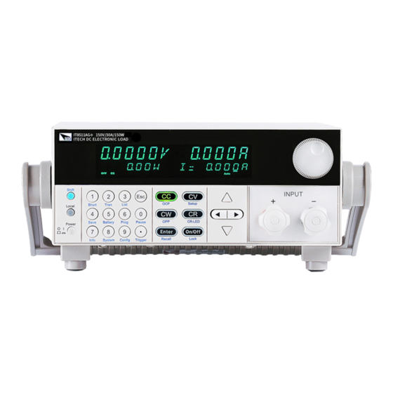
DC Programmable Electronic
Loads
Series
IT8500G+
User Manual
Model: IT8511G+/IT8511AG+/IT8512G+/IT8512BG+
/IT8513G+/IT8513BG+/IT8513CG+
Version:3.0
Table of
Contents
Previous
Page
Next
Page
1
2
3
4
5
Advertisement
Table of Contents
Need help?
Do you have a question about the IT8500G+ Series and is the answer not in the manual?
Ask a question
Questions and answers
Related Manuals for ITech IT8500G+ Series
Power Supply ITech IT8500G+ Series User Manual
Dc programmable electronic loads (71 pages)
Network Hardware ITech IT8200 Series Programming Manual
Programmable dc electronic load (16 pages)
Network Hardware ITech IT-M3300 Series User Manual
Regenerative dc electronic load (135 pages)
Network Hardware ITech IT8513G+ User Manual
Dc programmable electronic loads (80 pages)
Network Hardware ITech IT-N2100 Series User Manual
Solar array simulator (65 pages)
This manual is also suitable for:
It8511g+
It8511ag+
It8512g+
It8512bg+
It8513g+
It8513bg+
...
Show all
It8513cg+
Table of Contents
Print
Rename the bookmark
Delete bookmark?
Delete from my manuals?
Login
Sign In
OR
Sign in with Facebook
Sign in with Google
Upload manual
Upload from disk
Upload from URL


Need help?
Do you have a question about the IT8500G+ Series and is the answer not in the manual?
Questions and answers