Table of Contents
Advertisement
Quick Links
Service Manual
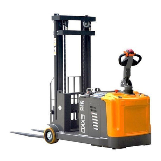
Counter Balanced Stacker
EK13, EK14, EK13S, EK14S
WARNING
You must understand the operation instructions in this manual
before using it.
Attention:
•
Please check the last page of this document and all
the current product type identification on the name
plate.
•
Keep it for future use
Advertisement
Table of Contents

Related Manuals for EKKO EK13


Summary of Contents for EKKO EK13
- Page 1 Service Manual Counter Balanced Stacker EK13, EK14, EK13S, EK14S WARNING You must understand the operation instructions in this manual before using it. Attention: • Please check the last page of this document and all the current product type identification on the name plate.
-
Page 2: Table Of Contents
Table of Contents Maintenance List ......................... 2 A. Overview of main components ....................2 B. Lubrication point ........................4 C. Check the fuse ........................... 6 Fault Analysis ..........................7 A. Common fault analysis......................7 B. The fault code display ....................... 8 Methods for troubleshooting common faults ................ -
Page 3: Maintenance List
1. Maintenance List A. Overview of main components List 1: Maintenance List Interval (month) 6 12 The hydraulic system • Check the hydraulic cylinder, piston for damage noise and leakage • Check hydraulic fittings and tubing for damage and leakage •... - Page 4 Driving system • 26 Check braking performance Storage Battery • 27 Checking the Battery voltage • 28 Clean and grease terminals and inspect for corrosion and damage • 29 Check whether the battery casing is damaged Charger • 30 Check whether the main power cable is damaged •...
-
Page 5: Lubrication Point
B. Lubrication points Lubricate marked points according to maintenance list. Required grease specification: DIN 51825 standard grease. Door frame track lubrication Chain lubrication... - Page 6 Axle lubrication A. Check and correct electrolytes The electrolyte density is based on 25℃.Therefore, when measuring, if the temperature of the electrolyte is higher or lower than 25℃, every 1℃ higher, should be measured from the actual density value plus 0.0007; On the contrary, lower than 25℃, every 1℃, should be minus 0.0007;If the temperature difference is large.
-
Page 7: Check The Fuse
C. Check the fuse 200Afuse List 2: Fuse specification Specification Fuse 1 200A... -
Page 8: Fault Analysis
2. Fault analysis If the vehicle continues to malfunction, follow the instructions of the manual. A. Common fault analysis Hand and foot break common faults and troubleshooting methods Fault Cause Maintenance Check the battery connector and The battery connector is not connected connect it if necessary The electric lock switch is in "OFF"... -
Page 9: The Fault Code Display
If the vehicle is malfunctioning and cannot be operated outside the work area, lift the vehicle up, place a load handling device under the vehicle and secure the vehicle, then remove the vehicle out of the channel. B. The fault code display Table 4:1212P fault codes The fault phenomenon Programmer display... -
Page 10: Methods For Troubleshooting Common Faults
C. Methods for troubleshooting common faults 1、Code 4.5 Battery is not connected Check whether the fastening of cable terminals of the car body is loose, as shown • Check whether the cable connection (including other secured parts) is loose • 2. - Page 11 1、Codes 3.4 and 3.2 Electromagnetic brake line problems, or electromagnetic brake failure Use a multimeter to measure the resistance of the two cores on the controller to the plug-in. The specific operations are as follows: Normally, it should be about ω.
- Page 12 4.2 Motor voltage cannot match accelerator input, motor or motor ring short circuit and controller fault, troubleshooting operations are shown as follows: Switch the multimeter to 20V DC, insert the pen j1-1 (accelerator 0-5V speed signal) and 2 (negative pole) respectively, turn the accelerator after power on, and observe whether the multimeter reading has 0-5V voltage linear change...
- Page 13 1、 Here is the coil wiring of the lifting contactor (line numbers are 2 and 15). After powering on, press the lifting button to measure whether there is a voltage of about 24V at these two places. If so, and there is no sound of pulling on the contactor, then the contactor is faulty.
- Page 14 Specific operation are as follow: The wrench unscrewed the pressure nut. Using an inner hexagon wrench, adjust the pressure.
-
Page 15: Wiring/Circuit Diagram
3. Wiring/circuit diagram A. Schematic diagram and wiring diagram... -
Page 16: Hydraulic Circuit
B. Hydraulic circuit Hydraulic circuit Hydraulic oil inspection Appearance Odor Condition Results Clear not discoloration good good can be used check viscosity, if qualified can color transparency good with other oil mix continue to use to separate moisture or replace Color changes like milk well mixed with air and water... -
Page 17: Disassembly Of Main Parts
4. Disassembly of main parts A. Removal of handle assembly... - Page 18 Code Name Quantity Remark SL20GA-01.6.3 Electromagnetic brake magnetic sensor assembly GB/T 70.1-2000 M6×150 Hexagon socket head screws SL20GA-01.6.7 Ac motor GB/T 70.1-2000 M8×20 Hexagon socket head screws Φ8 GB/T 93-1987 Elastic washer GB/T 70.1-2000 M12×50 Hexagon socket head screws Φ12 GB/T 93-1987 Elastic washer ZD-ZV21-500-...
-
Page 19: Removal Of Electric Control Component
B. Removal of electric control component Code Name Specification Quantity REMARK GB/T 70.1-2000 M10×25 Hexagon socket head screws Φ10 GB/T 93-1987 Elastic washer SL20GA- The cover plate 01.10.6 GB/T 70.2-2000 M8×16 Hexagon socket flat round head screws SL20GA- The silicone tube 01.10.1.4 SL20GA- 01.10.1.2... - Page 20 E10GL-02.2.3 Spring seat E10GL-02.2.1 Casing welding SL20GA- Steering sensor 01.10.3 SL20GA- Mounting plate 01.10.1.7 TY-01.7 Micros witch RV-166-1C25 GB/T 70.1-2000 Hexagon socket screw GB/T 70.2-2000 M5×16 Hexagon socket flat round head screws SL20GA- Outer cover plate 01.10.7 TY-01.12 handle T606-1 GB/T 70.1-2000 M6×25 Hexagon socket head screws...
-
Page 21: Hydraulic Assembly Removal
C. Hydraulic assembly removal Code Name Specification Quantity E10GS-03.4 Lift cylinder assembly CL10.4.3 Anti-riot valve spool Φ16 GB982-77 Combination gasket E10GS-01.8.7 Directly to the head E10GL-03.5 Steel pipe Φ20 GB892-77 Combination gasket E10GL-03.6 Right Angle adjustable joint E10GL-01.6.5 Tilt hose E10GL-01.6.4 Lifting hose E10GS-01.7.1... -
Page 22: Arm Guard Assembly Removal
D. Arm Guard Assembly Removal Code Name Specification Quantity Remark SL30GB-04.1 Boom guard welded SL30GB-04.2 shield Φ48 GB 894.1-86 Shaft with elastic retainer SL30GB- gasket 01.3.4 SL30GB- bushing 01.3.5 SL30GB- Shaft sleeve left 01.3.2 GB/T 79-2000 M8×12 Hexagon socket point set screws SL30GB- Arm guard seat welded... -
Page 23: Mast Assembly
E. Mast Assembly Code Name Specification Quantity E10GL-06.4 Carriage components Φ25 GB 894.1-86 Shaft with elastic retainer GB/T 276-94 6305-2Z Deep groove ball bearing CG1646.03.3-5 Sprocket a. CL1032C.02-09 Sprocket shaft Φ10 GB/T 93-1987 Elastic washer GB/T 70.1-2000 M10×20 Hexagon socket head screws CL1555QD.02.07 Sprocket frame welding E10GL-06.10... - Page 24 E10GL-06.8 Steel Pipe (2) E10GL-06.3 Internal door frame assembly LH0866 Plate chain E10GL-06.2 Middle gantry assembly E10GL-03.1 External door frame assembly E10GL-06.6 Rear lift cylinder assembly E10GS-03.7 The door frame spacing GB/T 70.1-2000 M8×30 Hexagon socket head screws Φ8 GB/T 93-1987 Elastic washer E10GL-06.7 Steel Pipe (1)
-
Page 25: External Door Frame Removal
F. External door frame removed Code Name Specification Quantity Remark GB/T 70.1- M8×20 Hexagon socket head 2000 screws Φ8 GB/T 93-1987 Elastic washer E10GS-03.1.4 Oil cylinder hoop GB/T 70.1- M6×10 Hexagon socket head 2000 screws Φ6 GB/T 93-1987 Elastic washer Φ21 the hoop CRA70.4-4S... - Page 26 TY-01.35 Micro switch RZ- 15GW2S-B3 GB/T 818-2000 M4×25 Cross recessed pan head screws Φ12 R type hoop E10GL-06.1.1 The outer door frame is welded E10GS-03.10 The door frame is connected with copper bushing TY-01.38 Proximity switch CLJF20-05FA Φ3 GB/T 93-1987 Elastic washer GB/T 818-2000 M3×20...
-
Page 27: Middle Door Frame Removal
G. Middle Door Frame Removal Code Name Specification Quantity GB/T 70.1-2000 M10×30 Hexagon socket head screws Φ10 GB/T 93-1987 Elastic washer E10GL-06.2.1 Middle frame welding GB/T 5781-2000 M14×55 Hexagon head bolt E10GS-07.2.3 Pulley casing E10GS-07.2.2 The pulley Φ14 GB/T 95-2002 Flat washer Φ14 GB/T 93-1987... -
Page 28: Inner Door Frame Removal
H. Inner Door Frame Removal Code Name Specification Quantity E10GL-06.3.1 Inner door frame welded Φ10 GB/T 95-2002 Flat washer Φ10 GB/T 93-1987 Elastic washer GB/T 70.1-2000 M10×40 Hexagon socket head screws CL1555QD.02.03.01-1 Tubing fixing plate Φ12 The hoop GB/T 70.1-2000 M6×10 Hexagon socket head screws Φ6... -
Page 29: Electrical Assembly
I. Electrical Assembly Code Name Specification Quantity Remark TY-02.57 Large power socket assembly GB 2673-86 M6×12 Hexagon socket countersunk head screws TY-01.14 Emergency stop switch ZDK31- GB/T 70.1- M6×20 Hexagon socket head screws 2000 Φ6 GB/T 93-1987 Elastic washer Φ6 GB/T 95-2002 Flat washer E10GL-01.15... - Page 30 TY-01.49 Steering control 1212P-2502 Φ4 GB/T 859-1987 Spring washer GB/T 70.1- M4×30 Hexagon socket head screws 2000 TY-01.28 80×80 GB/T 818-2000 M4×40 Cross recessed pan head screws GB 2673-86 M8×20 Hexagon socket countersunk head screws E10GL-01.6.1 Neutral plate welding TY-01.18 The horn DC24 Φ...
-
Page 31: Curtis Handhold Unit
5. CURTIS Handheld unit Precautions for operation: The attention function of the hand-held unit is to facilitate vehicle inspection and maintenance. It is not allowed to adjust the controller parameters without the approval of the vehicle manufacturer, so as to avoid vehicle and personal safety accidents. - Page 32 The programmer is powered on...
- Page 33 The connection line of the handheld programmer can be connected to the controller by inserting the programming port of the controller. After connecting the controller, the handheld programmer will be powered on automatically and the control information will be displayed on the programmer. The function keys Since the function of the three keys...
- Page 34 The menu structures The main menu consists of nine sub-menus, and each sub-menu is displayed with a specific icon. Each item in the sub- menu is arranged by hierarchy. Some menus contain only one item of information, but most menus contain more than one item of information and open each item folder to access the next level of sub menus.
- Page 35 Fault Diagnosis menu On the main menu, Select Diagnostics and press select to access the Fault diagnosis menu. The Fault diagnosis menu contains Present Errors current faults and Fault History historical faults Note: Sometimes a fault caused by a temporary event captured in the circuit is not a system fault. You can determine whether the fault exists by restarting the system and observing whether the fault disappears automatically.
Need help?
Do you have a question about the EK13 and is the answer not in the manual?
Questions and answers