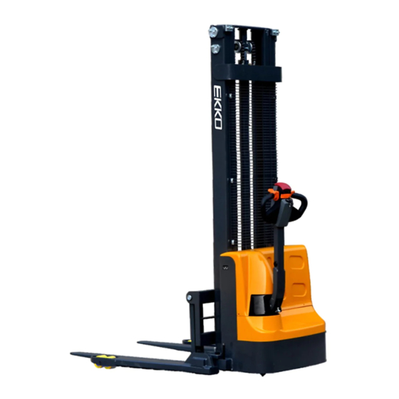
EKKO EB12E-119 Service Manual

EKKO EB12E-119 Service Manual

Walkie electric stacker

Advertisement

Service Manual
Walkie Electric Stacker
EB12E-119/138, EB12E-98Li, EB13E-119/138
EB13ES-145Li, EB13E-119/138/145 Li
WARNING
You must understand the operation instructions in this manual
before using it.
Attention:
Please check the last page of this document and all
the current product type identification on the name
plate.
Keep it for future use

Advertisement

Table of Contents
loading

Summary of Contents for EKKO EB12E-119

  • Page 1 Service Manual Walkie Electric Stacker EB12E-119/138, EB12E-98Li, EB13E-119/138 EB13ES-145Li, EB13E-119/138/145 Li WARNING You must understand the operation instructions in this manual before using it. Attention: • Please check the last page of this document and all the current product type identification on the name plate.
  • Page 2: Table Of Contents

    Table of Contents 1. Maintain list ....................1 A. Main part overview ................1 B. Lubrication point ..................3 C. Check and refill hydraulic oil ..............5 D. Check electrical fuses ................6 2. Failure analysis ..................7 A. Common failure analysis ............... 7 B.
  • Page 3: Maintain List

    1. Maintain list A. Main part overview Table 1: Maintain list Time interval (Month) Hydraulic system • Check the hydraulic cylinder and the piston for damage, noise, and leakage. • Check the hydraulic connector for damage and leakage. • Check the Hydraulic oil level and refill if necessary. •...
  • Page 4 • Check whether the battery cover is damaged Charger • Check whether the main cable is damaged. • Check the startup protection program during charging Function • Check the horn function • Check the air gap of the solenoid valve •...
  • Page 5: Lubrication Point

    B. Lubrication point Lubricate the marked points according to the maintenance list. The required grease specification is DIN51825 standard Grease. Pic.1: Lubrication point Tapered bearing Butter filler...
  • Page 6 Sliding way in the mast Chain Lubrication...
  • Page 7: Check And Refill Hydraulic Oil

    Shaft lubrication C. Check and refill hydraulic oil According to the temperature, the recommended hydraulic oil type as below: Temperature –5℃~25℃ >25℃ HVLP 32, HLP 46, Model DIN 51524 DIN 51524 Viscosity 28.8-35.2 41.4 - 47 Oil volume 1.5 L Waste materials such as waste oil, batteries or other materials must be processed and recycled in accordance with national regulations and if necessary, they must be handed over to recycling companies for recycling.
  • Page 8: Check Electrical Fuses

    D. Check electrical fuses 200A Fuse 10A fuse Table 2: Fuse specification Specification Fuse 1 Fuse 01 200A...
  • Page 9: Failure Analysis

    2. Failure analysis A. Common failure analysis Table 3: Failure analysis Malfunction Cause Solution Only lifting max capacity shown Overload on name plate Battery discharge Charge the battery Check and replace the lifting Goods can’t be Lift fuse damaged fuse if necessary lifted up Check and refill hydraulic oil if Low hydraulic oil level...
  • Page 10: Controller Fault Code Display

    B. Controller fault code display Table 4: 1212P fault code Programmer Code Failure phenomenon Troubleshooting display BATTERY Battery disconnected 1) Battery not connected DISCONNECT 2) Poor connection to battery FAULT terminals BRAKE OFF BRAKE OFF FAULT 1) Electromagnetic brake coil FAULT shorted 2) Electromagnetic brake driver...
  • Page 11: Troubleshooting For Common Faults

    Speed limited pot wiper SPEED POT 1) Speed limit pot wire(s)broken or out of range FAULT shorted 2) Speed limit pot wire(s)open THERMAL FAULT Over-/under- 1) temperature>80℃ or <-10℃ temperature cut back 2) Excessive load on truck 3) Operating in extreme environment 4) Electromagnetic brake not releasing...
  • Page 12 Battery cell with load measurement, Cell voltage drop should between 2-3V. Code 3.4 and 3.2 Electromagnetic brake cable issue or electromagnetic brake failure Use a multimeter to measure the resistance of the two-core plug-in on the controller. Shown below Unplug 2-core plug in of the controller. Turn the multimeter to 200Ω, and measure the resistance between the two wires on the plug-in Normally it should be...
  • Page 13 Turn the Multimeter to 24V DC, insert the pin into J1-1(Accelerator 0- 5v speed signal)2(Negative). Turn the accelerator after Power-on. And observe whether the Multimeter reading has a linear change of 0-5v voltage Please replace the controller If the voltage of the accelerator changes normally . D.
  • Page 14 The unit isn’t lifting up & lowering down or oil cylinder lowered itself, Troubleshooting operations as below steps: Here is the coil wiring of the lifting contractor (wire No.5&No.15) After power on, Press lifting button and then measure whether there is a voltage about 24V from these two places.
  • Page 15 3.If the truck can’t lift goods normally. For example. the truck with 1.5T loading capacity but can only lift goods less than 1T, then we can adjust the oil pump pressure to reach 1.5T loading capacity. But the operation must be carried out carefully. P.S.: Don’t adjust the hydraulic pressure exceed the rated load.
  • Page 16: Wiring/Circuit Diagram

    3. Wiring/circuit diagram A. Circuit diagram...
  • Page 18: Oil Hydraulic Circuit

    B. Oil hydraulic circuit Lifting cylinder Lowering valve Pressure controller Throttle valve valve Hydraulic power unit (Motor or oil pump) Oil tank C. Hydraulic oil inspection Exterior Smell Condition Result Clear and no color Good Good Can be used Check the viscosity. You Transparent Good Mixed with other oil...
  • Page 19: Disassembly Of Main Parts

    4. Disassembly of main parts A. Electromagnetic brake adjustment Adjust nut The electromagnetic brake gap is about 25- Note: The electromagnetic brake 35CM, about one hundred yuan in thickness. It can't be properly connected when needs to be carefully and carefully adjusted to it is energized in the free state.
  • Page 20: Disassembly Of Electromagnetic Brake

    C. Disassembly of brake and driving wheel D. Driving internal gears and bearings...
  • Page 21: Operating Handle Assembly

    E. Operating handle assembly F. The mechanical part of electric stacker...
  • Page 22: Pump Motor

    G. Economic electric stacker fork carriage assembly H. Pump motor...
  • Page 23: Curtis Handle Programmer Manual Content

    5. CURTIS handle programmer Operation precautions: Handle programmer, the main function is to facilitate unit inspection and maintenance. To avoid accidents, it is not allowed to be used to adjust the controller parameters. After modifying the parameter, it will be saved automatically, just turn off the key switch and restart the unit.
  • Page 24 CURTIS handle programmer manual content Curtis 1313 handheld programmer is used to configure the Curtis electronic control system. Through this programmer, you can adjust and save the set parameters, real-time monitoring of controller data and fault diagnosis Warning: The control system will affect the acceleration rate, deceleration rate, hydraulic system, and brakes of the truck.
  • Page 25 Function keys Since the functions of these three buttons are determined according to the specified content, these three buttons are blank. At any given time, the function of the button will be displayed on the upper LCD screen. Arrow keys The displayed information can be selected up, down, left, and right through the 4 Arrow keys .+/-keys...
  • Page 26 Menu structure The main menu consists of nine sub-menus, each of which is displayed with a specific icon, and each item in the sub-menu is arranged hierarchically. Some menus only contain one item of information, but most menus contain multiple pieces of information. You can enter the next submenu by opening each folder.
  • Page 27 Fault diagnosis menu In the main menu, select the "Diagnostics" fault diagnosis icon, and press the corresponding function key of Select to enter the fault diagnosis menu. The fault diagnosis menu includes two folders: "Present Errors" current fault and "Fault History" historical fault Note: Sometimes the fault caused by the temporary event captured in the circuit is not a system fault.

Table of Contents