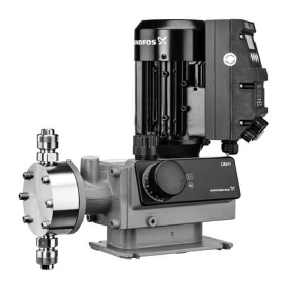
Grundfos DMH 25X Installation And Operating Instructions Manual
Dosing pump
Hide thumbs
Also See for DMH 25X:
- Instructions manual (52 pages) ,
- Installation and operating instructions manual (14 pages)

Related Manuals for Grundfos DMH 25X


Summary of Contents for Grundfos DMH 25X
- Page 1 GRUNDFOS INSTRUCTIONS DMH 25X Dosing pump Installation and operating instructions DMH 25x Installation and operating instructions http://net.grundfos.com/qr/i/99558949...
- Page 3 DMH 25X English (GB) Installation and operating instructions ............4 Čeština (CZ)
-
Page 4: Table Of Contents
Weight ....... . 22 The DMH 25X pump is suitable for liquid, non-abrasive and non- Stroke volume . -
Page 5: Safety
The pump housing, control unit and sensors must only be damages may be lost. opened by personnel authorised by Grundfos! Non-observance of the safety instructions may lead to the following Repairs must only be carried out by authorised and quali-... -
Page 6: Unauthorised Modification And Manufacture Of Spare Parts
Marks of approval dosing system Pump model DMH 25X dosing pumps are designed according to the latest Production code (year and week) technologies and are carefully manufactured and tested. However, a failure may occur in the dosing system. Systems in which dosing... - Page 7 3.1.2 Type key Valve ball material The type key is used to identify the precise pump and is not used DMH1150-10D B-PVC/V/G-X-E1B8B8XEMAG for configuration purposes. Glass (from DN 32) Type PTFE Stainless steel, 1.4401 (EN 10027-2), 316 (AISI) DMH1150-10D B-PVC/V/G-X-E1B8B8XEMAG Ceramic (up to DN 20) Nominal dosing capacity [l/h] Alloy C-4, 2.4610 (EN 10027-2)
- Page 8 EX motor, type EX II 2GD EEx de IIC T4, without PTC (with certificates) Pump with API approval (with pump and motor certificates) EX motor, type EX II 2GD EEx de IIC T4, with PTC (with certificates) Pump housing material DMH1150-10D B-PVC/V/G-X-E1B8B8XEMAG Aluminium Grey cast iron Pump design DMH1150-10D B-PVC/V/G-X-E1B8B8XEMAG Grundfos Neutral...
-
Page 9: Pump Models And Pump Types
3.2 Pump models and pump types The DMH 25X dosing pump is available for a variety of performance ranges in various sizes. The pump nameplate shows various data of the pump like the type designation and the pump model. For an explanation of the nameplate see section Nameplate. - Page 10 50 Hz 60 Hz 100 Hz Max. Max. Max. Pump model Pump type p max. stroke p max. stroke p max. stroke rate rate rate [l/h] [bar] [n/min] [l/h] [bar] [n/min] [l/h] [bar] [n/min] DMH 50-10 DMH 97-16 DMH 102-10 DMH 136-16 DMH 143-10 DMH 254...
-
Page 11: Sound Pressure Level
DMH 255 Flooded suction deaeration • memory function (stores a maximum of 65,000 pulses) DMH 272-16 • two-stage tank-empty signal (e.g. via Grundfos tank empty DMH 340-16 Flooded suction sensor) DMH 440-10 • stroke signal/pre-empty signal (adjustable), e.g. as a feedback... -
Page 12: Power Supply
Note Make sure that the pump is suitable for the actual dosing please contact Grundfos. medium! The dosing medium must have the following basic characteristics for the standard pumps: •... -
Page 13: Transport And Storage
If proper cleaning is not possible, all relevant information about the chemical must be provided. If the above is not fulfilled, Grundfos Water Treatment can refuse to accept the pump for service. Possible costs of returning the pump are paid by the customer. -
Page 14: Product Description And Accessories
5. Product description and accessories 5.1 General description The DMH 25X are positive-displacement pumps with hydraulic The hydraulic-driven movement of the PTFE diaphragm (Q) diaphragm control. The operation procedure of the dosing pump is displaces an equivalent volume of dosing medium from the dosing shown in the sectional drawing. - Page 15 ε χ DMH 254 DMH 255...
- Page 16 DMH 257 Pos. Components Motor Worm gear Eccentric Return spring (not with drive size 3) Sliding sleeve Piston Crank Combined pressure-relief and degassing valve Degassing valve Diaphragm protection system (AMS) Dosing diaphragm Dosing head Suction valve Discharge valve Stroke-length adjustment knob Oil-filling screw with dipstick 5.1.1 Combined pressure-relief and degassing valve The combined pressure-relief and degassing valve (M) opens if...
- Page 17 5.1.3 Double-diaphragm system/diaphragm leakage detection Functional principle of diaphragm leakage detection (optional) The non-return valve and the gap between the diaphragms are factory-filled with a separating agent (paraffin oil). They are set in General such a way during start-up on the test stand that there is always a The piston diaphragm and high-tech dosing pumps with drift-free hydraulically separated equilibrium between the valve and diaphragm leakage detection are equipped with the following:...
-
Page 18: Dimensions
5.2 Dimensions 5.2.1 Dimensions of DMH 251, 252, 253 and 254 single-head pumps All dimensions are in mm, except for the thread designations. Pump model DMH 251 97,5 G 5/8 85,5 117,5 DMH 252 97,5 G 5/8 85,5 117,5 DMH 253 97,5 G1 1/4 117,5... - Page 19 5.2.3 Dimensions of DMH 255 single-head pumps with G 1 1/4 inlet connection All dimensions are in mm, except for the thread designations. Pump model DMH 255 G1 1/4 10,5 5.2.4 Dimensions of DMH 255 single-head pumps with flange on inlet side All dimensions are in mm, except for the thread designations.
- Page 20 5.2.5 Dimensions of DMH 255 double-head pumps with G 1 1/4 inlet connection All dimensions are in mm, except for the thread designations. Pump model DMH 255 G1 1/4 10,5 5.2.6 Dimensions of DMH 255 double-head pumps with flange on inlet side All dimensions are in mm, except for the thread designations.
- Page 21 5.2.7 Dimensions of DMH 257 single-head pumps All dimensions are in mm, except for the thread designations. Pump Pump connec- model tion size D1 DMH 257 DN32 24,5 128,5 194,5 DMH 257 ANSI 1 1/4 24,5 128,5 194,5 5.2.8 Dimensions of DMH 257 double-head pumps All dimensions are in mm, except for the thread designations.
-
Page 22: Weight
5.3 Weight 5.5 Materials Pump housing material Weight [kg] • Pump housing: Al 226. Pump model Dosing head material Single Double AR control unit enclosure pump pump • Upper part of enclosure: PPO blend PVC, PP, PVDF • Lower part of enclosure: aluminium. DMH 251 Stainless steel 1.4571 Alloy C-4, 2.4610... -
Page 23: Installation
6. Installation 6.4 Approximate values when using pulsation dampers Risk of damage to the system! 6.1 General information on installation It is always recommended to use pulsation dampers for Warning large high-speed pumps! Observe the specifications for the installation location and In particular for pump types with a flow rate above 1000 range of applications described in section Technical data. - Page 24 Pump model / pump Nominal width of Maximum length of type suction line suction line [m] DMH 175-10 DN 20 DMH 202-16 DN 20 DMH 213-10 DN 20 DMH 276-16 DN 20 DMH 291-10 DN 20 DMH 255 DMH 194-10 DN 20 DMH 270-10 DN 20...
-
Page 25: Optimum Installation
6.5 Optimum installation max. 1m Example of optimum installation Pos. Components Dosing tank Electric agitator Extraction device Suction pulsation damper Dosing pump Relief valve Pressure-loading valve Pulsation damper Measuring glass Injection unit... -
Page 26: Installation Tips
6.6 Installation tips Observe section Approximate values when using pulsa- tion dampers and, if necessary, request a system-specific Note • For easy deaeration of the dosing head, install a ball valve (11i) calculation from our calculation program. with bypass line (back to the dosing tank) immediately after the discharge valve. -
Page 27: Tube / Pipe Lines
A positive pressure difference of at least 2 bar must be ensured 6.7 Tube / pipe lines between the counter-pressure at the injection point and the 6.7.1 General pressure of the dosing medium at the pump suction valve. • If this cannot be ensured, install a pressure-loading valve (7i) in Warning the discharge line. -
Page 28: Electrical Connections
Observe the local safety regulations! The pump housing must only be opened by personnel au- thorised by Grundfos! Protect the cable connections and plugs against corrosion and humidity. Only remove the protective caps from the sockets that are being used. -
Page 29: Diaphragm Controller (Optional)
7.4 Diaphragm controller (optional) 7.5 Connecting the power supply cable Warning Warning Disconnect the power supply before connecting the power Explosion-proof pumps with diaphragm leakage detection supply cable! are fitted with a contact pressure gauge in explosion-proof Before connecting the power supply cable, check that the version. -
Page 30: Start-Up/Shutdown
The pump housing must only be opened by personnel au- 2. Add the dosing medium to the dosing head (2). thorised by Grundfos! 3. Screw the discharge valve (3b) back in. Repairs must only be carried out by authorised and quali-... -
Page 31: Start-Up/Subsequent Start-Up Of Dmh 254, 255 And
Note Immersion depth to marking: approx. 5 mm. Check the oil level at least every two weeks and add oil, if necessary. Only use original Grundfos gear oil! Note For product numbers, see "Service kit catalogue" on www.grundfos.com Start-up of DMH 254, 255 and 257... -
Page 32: Setting The Pressure Relief Valve
After start-up After initial start-up and after each time the diaphragm is changed, tighten the dosing head screws. After approximately 6-10 operating hours or two days, Caution cross-tighten the dosing head screws using a torque wrench. Torques Torque Pump model [Nm] DMH 254 50-54... -
Page 33: Operating The Pump
8.7.3 Storage Warning Storage of the pump: When dosing dangerous media, observe the correspond- ing safety precautions! 1. After cleaning, carefully dry all parts and reinstall the dosing head and valves, or Wear protective clothing (gloves and goggles) when work- ing on the dosing head, connections or lines! 2. -
Page 34: Operation
9. Operation 9.3 Using the AR control unit (optional) When using the AR control unit, observe the installation and 9.1 Switching on/off operating instructions for the "AR control unit" in addition to the instructions in this manual. Before switching on the pump, check that it is installed correctly. -
Page 35: Maintenance
The pump housing must only be opened by personnel au- Clean the valves and replace, if necessary (for stainless-steel thorised by Grundfos! valves: inner valve parts). Repairs must only be carried out by authorised and quali-... - Page 36 Stainless-steel (1) or plastic (2) DN 20 valve, spring-loaded as an Stainless-steel or plastic DN 8 valve, spring-loaded as an option option Plastic DN 20 valve DN 32 valve, suction side (1) and discharge side (2) The O-rings must be correctly placed in the specified groove.
-
Page 37: Detection)
Before removing the dosing head, valves and lines, empty suction side. any remaining medium in the dosing head into a drip tray by carefully unscrewing the suction valve. Only use original Grundfos gear oil! Note For product numbers, see "Service kit catalogue" on www.grundfos.com... -
Page 38: Diaphragm
Q2)! See fig. Diaphragm on dosing-head side. Caution Fit the thinner diaphragm (Q1) on the dosing side and Only use original Grundfos gear oil! the thicker diaphragm (Q2) on the oil side/pump side! For product numbers, see "Service kit catalogue" on Note www.grundfos.com... - Page 39 DMH 257 10.7.3 Fitting the dosing head For product numbers of double-diaphragm filling compo- Note nents, see "Service kit catalogue" on www.grundfos.com • Fit the dosing head and cross-tighten the dosing head screws using a torque wrench. 10.7.5 Filling with gear oil...
- Page 40 10.7.7 Cleaning the ball non-return valve Cleaning the ball non-return valve Only clean the ball non-return valve after a diaphragm Note breakage! Contact pressure gauge Pos. Components Contact pressure gauge Union nut Ball non-return valve Contact output Ball non-return valve Pos.
-
Page 41: Fault Finding Chart
11. Fault finding chart Warning Actions that are taken to correct faults on the pump and that are not described in this manual, must only be carried out by personnel authorised by Grundfos! Fault Diagnosis Cause Remedy No motor sound or vibrations. - Page 42 Fault Diagnosis Cause Remedy Suction valve: During the discharge stroke, the dosing liquid flows back in- to the suction line. Discharge valve: During the suction Suction/discharge valves dirty or leaky. Clean or replace valves. stroke, the dosing liquid flows back in- to the dosing head.
-
Page 43: Dosing Curves
This product or parts of it must be disposed of in an environmentally sound way. 1. Use the public or private waste collection service. 2. If this is not possible, contact the nearest Grundfos company or service workshop. The crossed-out wheelie bin symbol on... - Page 44 Appendix A A.1. Dosing curves DMH 2,4-10 (50 Hz) Q = 3 bar DMH 251 Q [l/h] DMH 2,2-25 (50 Hz) Q = 20 bar 3 bar 10 bar Q [l/h] 20 bar 25 bar 10 bar 90 100 h [% ] DMH 2,4-10 (60 Hz) Q = 3 bar 90 100...
- Page 45 DMH 4,9-16 (50Hz) Q = 10bar DMH 11-25 (50Hz) Q = 20bar Q [l/h] Q [l/h] 3bar 20bar 10bar 25bar 16bar 10bar 10 20 30 40 50 60 70 80 90 100 h [%] 10 20 30 40 50 60 70 80 90 100 h [%] DMH 4,9-16 (60Hz) Q = 10bar...
- Page 46 DMH 13-10 (50Hz) Q = 3bar DMH 18-16 (50Hz) Q = 10bar Q [l/h] Q [l/h] 3bar 3bar 10bar 10bar 16bar 10 20 30 40 50 60 70 80 90 100 10 20 30 40 50 60 70 80 90 100 h [%] h [%] DMH 18-16 (60Hz) Q...
- Page 47 DMH 252 DMH 21-25 (50Hz) Q = 20bar DMH 10-16 (50Hz) Q = 10bar Q [l/h] Q [l/h] 20bar 25bar 10bar 16bar 10bar 10 20 30 40 50 60 70 80 90 100 h [%] 10 20 30 40 50 60 70 80 90 100 h [%] DMH 10-16 (60Hz) Q = 10bar...
- Page 48 DMH 23-16 (50Hz) Q = 10bar DMH 36-16 (50Hz) Q = 10bar Q [l/h] Q [l/h] 16bar 16bar 10bar 10bar 10 20 30 40 50 60 70 80 90 100 10 20 30 40 50 60 70 80 90 100 h [%] h [%] DMH 23-16 (60Hz) Q...
- Page 49 DMH 253 DMH 45-16 (50Hz) Q = 10bar DMH 21-10 (50Hz) Q = 3bar Q [l/h] Q [l/h] 16bar 10bar 3bar 10bar 10 20 30 40 50 60 70 80 90 100 h [%] h [%] DMH 45-16 (60Hz) Q = 10bar DMH 21-10 (60Hz) Q = 3bar...
- Page 50 DMH 67-10 (50Hz) Q = 3bar DMH 100-10 (50Hz) Q = 3bar Q [l/h] Q [l/h] 3bar 10bar 3bar 10bar 90 100 h [%] h [%] DMH 254 DMH 67-10 (60Hz) Q = 3bar DMH 46-16 (50 Hz) Q = 10 bar Q [l/h] Q [l/h] 10 bar...
- Page 51 DMH 50-10 (60 Hz) Q = 3 bar DMH 102-10 (60Hz) Q = 3bar Q [l/h] Q [l/h] 3 bar 10 bar 3bar 10bar 10 20 30 40 50 60 70 80 90 100 h [%] 90 100 h [% ] DMH 136-16 (50Hz) Q = 10bar DMH 97-16 (50Hz) Q...
- Page 52 DMH 143-10 (60Hz) Q = 3bar DMH 175-10 (60Hz) Q = 3bar Q [l/h] Q [l/h] 3bar 3bar 10bar 10bar 10 20 30 40 50 60 70 80 90 100 10 20 30 40 50 60 70 80 90 100 h [%] h [%] DMH 166-16 (50Hz) Q...
- Page 53 DMH 213-10 (60Hz) Q = 3bar DMH 194-10 (60Hz) Q = 3bar Q [l/h] Q [l/h] 3bar 3bar 10bar 10bar 90 100 10 20 30 40 50 60 70 80 90 100 h [%] h [%] DMH 270-10 (50Hz) Q = 3bar DMH 276-16 (50Hz) Q = 10bar...
- Page 54 DMH 257 DMH 332-10 (60Hz) Q = 3bar DMH 440-10 (50Hz) Q = 3bar Q [l/h] Q [l/h] 10bar 3bar 10bar 3bar 90 100 h [%] 90 100 h [%] DMH 403-10 (50Hz) Q = 3bar DMH 440-10 (60Hz) Q = 3bar Q [l/h] Q [l/h]...
- Page 55 DMH 750-4 (50Hz) Q = 3bar DMH 880-10 (50Hz) Q = 3bar 1.000 1200 Q [l/h] Q [l/h] 1000 2bar 3bar 4bar 10bar 90 100 h [%] h [%] DMH 750-4 (60Hz) Q = 3bar 1.000 DMH 880-10 (60Hz) Q = 3bar Q [l/h] 1200...
- Page 56 Appendix B B.1. Safety declaration • Please copy, fill in and sign this sheet and attach it to the product returned for service. • Fill in this document using English or German language. Fault description • Please make a circle around the damaged part. •...
- Page 57 Tel.: +387 33 592 480 Centre Turkey Fax: +387 33 590 465 29-33 Wing Hong Street & 68 King Lam GRUNDFOS Pumper A/S GRUNDFOS POMPA San. ve Tic. Ltd. Sti. www.ba.grundfos.com Street, Cheung Sha Wan Strømsveien 344 Gebze Organize Sanayi Bölgesi E-mail: grundfos@bih.net.ba...
- Page 58 99558949 05.2022 ECM: 1321884 www.grundfos.com...